Page is loading ...

Vermont Castings • Intrepid FlexBurn
®
Installation Manual_R15 • 2018 - ___ • 09/201 3-90-30007345i
Installation Manual
Installation & Appliance Set-Up
INSTALLER: Leave this manual with party responsible for use and operation.
OWNER: Retain this manual for future reference.
NOTICE: DO NOT DISCARD THIS MANUAL
NOTE
To obtain a French translation of this manual, please
contact your dealer or visit www.vermontcastings.com
Pour obtenir une traduction française de ce manuel, s’il
vous plaît contacter votre revendeur ou visitez www.
vermontcastings.com
If the information in these instructions is not
followed exactly, a re may result causing
property damage, personal injury, or death.
WARNING
!
• Donotstoreorusegasolineorotherammablevapors
and liquids in the vicinity of this or any other appliance.
• Donotoverre - If appliance or chimney connector
glows, you are over ring. Over ring will void your
warranty.
• Comply with all minimum clearances to combustibles
asspecied.Failuretocomplymaycausehousere.
Installationandserviceofthisapplianceshouldbeperformedby
qualiedpersonnel.Hearth&HomeTechnologiesrecommends
HHTFactoryTrainedorNFIcertiedprofessionals.
HOT SURFACES!
Glass and other surfaces are hot
duringoperationANDcooldown.
Hot glass will cause burns.
WARNING
!
• Do not touch glass until it is cooled
• NEVERallowchildrentotouchglass
• Keep children away
• CAREFULLYSUPERVISEchildreninsameroomas
replace.
• Alert children and adults to hazards of high
temperatures
• High temperatures may ignite clothing or other
ammable materials.
• Keep clothing, furniture, draperies and other
ammablematerialsaway.
Intrepid FlexBurn
®
Wood Burning Stove
Model2115/2115-CAT
NOTICE: SAVE THESE INSTRUCTIONS

Vermont Castings • Intrepid FlexBurn
®
Installation Manual_R15 • 2018 - ___ • 09/20 23-90-30007345i
TABLE OF CONTENTS
Safety Alert Key:
• DANGER! Indicatesahazardoussituationwhich,ifnotavoidedwill result in death or serious injury.
• WARNING!Indicatesahazardoussituationwhich,ifnotavoidedcould result in death or serious injury.
• CAUTION! Indicatesahazardoussituationwhich,ifnotavoided,could result in minor or moderate injury.
• NOTICE:Indicatespracticeswhichmaycausedamagetotheapplianceortoproperty.
Please read this entire manual before you install and use your new room heater. Failure to follow instructions may result in
property damage, bodily injury, or even death.
!
1 Important Safety Information
A. ApplianceCertication ............................................. 3
B. BTU&EciencySpecications ............................... 3
C. MobileHomeApproved(USAONLY) ...................... 3
D. GlassSpecications ................................................ 3
E. Non-CombustibleMaterials ..................................... 4
F. Combustible Materials ............................................. 4
G. CaliforniaSafetyInformation ................................... 4
2 Getting Started
A. DesignandInstallationConsiderations ................... 5
B. FireSafety ............................................................... 5
C. NegativePressure ................................................... 5
D. ToolsAndSuppliesNeeded ..................................... 6
E. InspectApplianceandComponents ........................6
F. InstallChecklist ........................................................ 7
3 Dimensions and Clearances
A. Appliance Dimensions ............................................. 8
B. HearthProtectionRequirements ............................. 9
C. Clearances to Combustibles .................................... 10
D. FireplaceInstallation ................................................ 11
E. LocatingYourAppliance&Chimney ........................ 12
F. ChimneyTerminationRequirements ........................12
G. ChimneyLocation(2-10-3Rule) .............................. 13
4 Chimney Systems
A. Venting&DraftManagement ...................................14
B. VentingComponents ..............................................15
C. ChimneySystems .................................................... 15
D. InstallingChimneyComponents .............................. 17
5 Appliance Set-Up
A. RemovingUnitFromSkid ........................................ 18
B. Assembly ................................................................. 18
C. InstallingOptionalCatalyst&PerfomancePack ..... 19
D. SmokeandCODetectors&SafetyTips ..................20
E. ReversibleFlueCollar ............................................. 21
F. OutsideAirInstallation ............................................. 21
6 Mobile Home Installation ......................................... 23
ContactInformation ....................................................... 24
= Contains updated information

Vermont Castings • Intrepid FlexBurn
®
Installation Manual_R15 • 2018 - ___ • 09/203 3-90-30007345i
A. Appliance Certication
EPA Report #:
114-18(without catalyst)
115-18(catalytic)
EPA Certied Emissions:
.6 g/hr (withoutcatalyst)
.3 g/hr (catalytic)
*LHV Tested Eciency:
80.3% (withoutcatalyst)
82.8% (catalytic)
**HHV Tested Eciency:
74.3% (withoutcatalyst)
76.7% (catalytic)
***EPA BTU Output:
12,500-18,500
(withoutcatalyst)
10,700-16,000
(catalytic)
****Peak BTU/Hour Output:
36,900(withoutcatalyst)
34,900(catalytic)
Vent Size: 6Inch(152mm)
Firebox Size: 1.3 cu. ft.
Recommended Length: 14”
Max. Wood Length: 15”
Fuel Orientation: East,West
Fuel
SeasonedCordwood
(20%moisture)
* Weighted average LHV eciency using Douglas Fir
dimensional lumber and data collected during EPA
emissions test.
**Weighted average HHV eciency using Douglas
Fir dimensional lumber and data collected during EPA
emissions test.
***Ecienciesarebasedontestresultscalculatedusing
B415; these calculated eciencies are then used to
calculateoutputBTU’s.
****ApeakBTUoutoftheappliancecalculatedusingthe
maximumrsthourburnratefromtheHighEPATestand
theBTUcontentofcordwood(8600)timestheeciency.
B. BTU & Eciency Specications
This wood appliance needs periodic inspection and repair for
properoperation.Itisagainstfederalregulationstooperate
this wood appliance in a manner inconsistent with operating
instructions in this manual.
C. Mobile Home Approved (USA ONLY)
• This appliance is approved for mobile home installations
in the USA when not installed ina sleepingroom and
when an outside combustion air inlet is provided.
• Thestructuralintegrityofthemobilehomeoor,ceiling,
and walls must be maintained.
• Theunitmust be boltedtotheoor.This canbedone
using an appropriate fastener for the application.
• The appliance must be properly grounded to the frame
of the mobile home with #8 copper ground wire, and
chimneymustbelistedtoUL103HToralistedUL-1777
fulllengthsix”(152mm)diameterlinermustbeused.
• Outsideairmustbeinstalledinamobilehomeinstallation.
• MobileHomeBracketKit#0003264mustbeinstalledin
a mobile home installation.
D. Glass Specications
This appliance is equipped with 5mm ceramic glass.
Replaceglassonlywith5mmceramicglass.Pleasecontact
your dealer for replacement glass.
1 1
Important Safety Information
MODEL: IntrepidFlexBurn
®
2115/2115-CAT
LABORATORY: OMNITestLaboratories,Inc
REPORT NO. 0135WS038S/0135WS038E
TYPE: SolidFuelTypeRoomHeaters
STANDARD(s): UL1482-2011(R2015),ULC-S627-00
Fire Risk.
Hearth & Home Technologies disclaims any
responsibility for, and the warranty will be voided
by, the following actions:
WARNING
!
• Installationanduseofanydamagedappliance.
• Modicationoftheappliance.
• InstallationotherthanasinstructedbyHearth&Home
Technologies.
• Installation and/or use of any component part not
approvedbyHearth&HomeTechnologies.
• Operating appliance without fully assembling all
components.
• Operatingappliancewithoutlegsattached(ifsupplied
withit).
• DoNOTOverre-Ifapplianceorchimneyconnector
glows,youareoverring.
Anysuchactionthatmaycausearehazard.
The Vermont Castings Intrepid FlexBurn
®
WoodAppliancemeetstheU.S.Environmental
Protection Agency’s crib wood emission limits
for wood appliances sold after May 15, 2020.

Vermont Castings • Intrepid FlexBurn
®
Installation Manual_R15 • 2018 - ___ • 09/204 3-90-30007345i
Improper installation, adjustment, alteration, service or
maintenance can cause injury or property damage.
Forassistanceoradditionalinformation,consultaqualied
installer, service agency or your dealer.
Hearth & Home Technologies WILL NOT warranty
appliancesthatexhibitevidenceofring.Evidenceofring
includes, but is not limited to:
• WarpedDamper
• Deteriorated refractory
• Deteriorated interior components
E. Non-Combustible Materials
Material which will not ignite and burn, composed of any
combination of the following:
-Steel -Plaster
-Brick -Iron
-Concrete -Tile
-Glass -Slate
Materials reported as passing ASTM E 136, Standard
Test Method for Behavior of Metals, in a Vertical Tube
Furnace of 750° C.
F. Combustible Materials
Material made of/or surfaced with any of the following
materials:
-Wood -CompressedPaper
-PlantFibers -Plastic
-Plywood/OSB -SheetRock(drywall)
Anymaterialthatcanigniteandburn:ameproofedornot,
plasteredornon-plastered.
NOTE:Thisinstallationmustconformwithlocalcodes.
Intheabsenceoflocalcodesyoumustcomplywiththe
UL1482-11,UL737-11,(UM)84-HUDandNPFA211in
theU.S.A.andtheULCS627-00andCAN/CSA-B365
Installation Codes in Canada. NOT APPROVED FOR
MOBILE HOME INSTALLATIONS IN CANADA!
NOTE:Hearth&HomeTechnologies,manufacturerofthis
appliance, reserves the right to alter its products, their
specicationsand/orpricewithoutnotice.
!
WARNING
This product and the fuels used to operate this product
(wood),andtheproductsofcombustionofsuchfuels,can
expose you to chemicals including carbon black, which
isknowntotheState ofCaliforniato causecancer,and
carbonmonoxide,whichisknowtotheStateofCalifornia
to cause birth defects or other reproductive harm. For
moreinformationgoto:www.P65Warnings.ca.gov
G. California Safety Information

Vermont Castings • Intrepid FlexBurn
®
Installation Manual_R15 • 2018 - ___ • 09/20 53-90-30007345i
A. Design and Installation Considerations
Consideration must be given to:
• Safety
• Convenience
• Tracow
• Chimney and chimney connector required
Itisagoodideatoplanyourinstallationonpaper,usingexact
measurementsforclearancesandoorprotection,before
actuallybeginningtheinstallation.Ifyouare notusingan
existing chimney, place the appliance where there will be a
clearpassageforafactory-builtlistedchimneythroughthe
ceiling and roof.
Werecommendthataqualiedbuildinginspectorandyour
insurance company representative review your plans before
and after installation.
Ifthisapplianceisinanareawherechildrenmaybenear
it is recommended that you purchase a decorative barrier
to go in front of the appliance.
Remembertoalwayskeep
children away while it is operating and do not let anyone
operate this appliance unless they are familiar with these
operating instructions.
C. Negative Pressure
Negativepressureresultsfromtheimbalanceofairavailable
fortheappliancetooperateproperly.Itcanbestrongestin
lower levels of the house.
Causes include:
• Exhaustfans(kitchen,bath,etc.)
• Rangehoods
• Combustion air requirements for furnaces, water
appliances and other combustion appliances
• Clothes dryers
• Locationofreturn-airventstofurnaceorairconditioning
• ImbalancesoftheHVACairhandlingsystem
• Upperlevelairleakssuchas:
- Recessedlighting
- Attichatch
- Ductleaks
B. Fire Safety
To providereasonablere safety,the following should be
given serious consideration:
1. Install at least one smoke detector on each oor of
your home to ensure your safety. They should be
located away from the heating appliance and close
to the sleeping areas. Follow the smoke detector
manufacturer’s placement and installation instructions,
and be sure to maintain regularly.
2 2
Getting Started
Checkbuildingcodespriortoinstallation.
• InstallationMUSTcomplywithlocal,regional,stateand
national codes and regulations.
• Consult insurance carrier, local building, reocials
or authorities having jurisdiction about restrictions,
installation inspection, and permits.
CAUTION
!
Asphyxiation Risk
• DONOTCONNECTTHISAPPLIANCETO
ACHIMNEYFLUESERVICINGANOTHER
APPLIANCE.
WARNING
!
• DONOTCONNECTTOANYAIRDISTRIBUTION
DUCTORSYSTEM.
Mayallowuegasestoenterthehouse.
2. AconvenientlylocatedClassAreextinguishertocontend
withsmallresresultingfromburningembers.
3. ACOdetectorshouldbeinstalledintheroomwiththe
appliance.
4. A practiced evacuation plan, consisting of at least two
escape routes.
5. Aplantodealwithachimneyreasfollows:
In the event of a chimney re:
a. Evacuatethehouseimmediately
b. Notifyredepartment.
Notice: Hearth & Home Technologies assumes no
responsibility for the improper performance of the
appliance system caused by:
• Inadequatedraftduetoenvironmentalconditions
• Down drafts
• Tight sealing construction of the structure
• Mechanical exhausting devices
• Overdraftingcausedbyexcessivechimneyheights
• Idealperformanceiswithachimneyheightof16Feet
(4.88m)measuredfromthebaseoftheappliance.
Asphyxiation Risk
• Negativepressure can cause spillage
of combustion fumes, soot and carbon
monoxide.
• Appliance needs to draft properly for safety.
WARNING
!

Vermont Castings • Intrepid FlexBurn
®
Installation Manual_R15 • 2018 - ___ • 09/206 3-90-30007345i
D. Tools And Supplies Needed
Before beginning the installation be sure the following tools
and building supplies are available:
E. Inspect Appliance and Components
• Removeapplianceandcomponentsfrompackagingand
inspect for damage.
• Reporttoyourdealeranypartsdamagedinshipment.
• Read all the instructions before starting the installation.
Follow these instructions carefully during the
installation to ensure maximum safety and benet.
Tominimizetheeectsofnegativeairpressure:
• Installunitwithoutsideairwiththeintakefacingprevailing
winds during the heating season
• Ensureadequateoutdoorairforall combustion appliances
and exhaust equipment
• Ensurefurnaceandairconditioningreturnventsarenot
located in the immediate vicinity of the appliance
• Avoidinstallingtheapplianceneardoors,walkways or
small isolated spaces
• Recessedlightingshouldbea“sealedcan”design
• Attic hatches weather stripped or sealed
• Atticmountedductworkandairhandlerjointsandseams
taped or sealed
• Basement installations should be avoided
•Reciprocatingsaw •Framingmaterial
• Pliers • Hightempcaulkingmaterial
•Hammer •Gloves
• Phillips screwdriver • Framing square
•Flatbladescrewdriver •Electricdrillandbits
•Plumbline •Safetyglasses
•Level •Tapemeasure
• Misc. screws and nails
•1/2-3/4in.length,#6or#8self-drillingscrews
• Installationanduseofanydamagedappliance.
• Modicationoftheappliance.
• InstallationotherthanasinstructedbyHearth&Home
Technologies.
• Installation and/or use of any component part not
approvedbyHearth&HomeTechnologies.
• Operating appliance withoutfully assembling all
components.
• Operatingwiththefrontdoorsopen.
• Operatingappliancewithoutlegsattached(ifsupplied
withappliance).
• DoNOTOverre-Ifapplianceorchimneyconnector
glows,youareoverring.
Any such action that may cause a re hazard.
Fire Risk.
Hearth&HomeTechnologiesdisclaimsany
responsibility for, and the warranty will be
voided by, the following actions:
WARNING
!
Fire Risk
Inspectapplianceandcomponentsfor
damage. Damaged parts may impair safe
operation.
• DoNOTinstalldamagedcomponents.
• DoNOTinstallincompletecomponents.
• DoNOTinstallsubstitutecomponents.
Reportdamagedpartstodealer.
WARNING
!
Whenthisroomheaterisnotproperlyinstalled,ahouse
re may result. To reduce the risk of re, follow the
installation instructions. Contact local building or re
ocials about restrictions and installation inspection
requirements in your area.
WARNING
!

Vermont Castings • Intrepid FlexBurn
®
Installation Manual_R15 • 2018 - ___ • 09/20 73-90-30007345i
ATTENTION INSTALLER:
Follow this Standard Work Checklist
Thisstandardworkchecklististobeusedbytheinstallerinconjunctionwith,notinsteadof,theinstructionscontainedinthisinstallationmanual
Customer:
DateInstalled:
Lot/Address:
LocationofAppliance:
Installer:
Dealer/ Distributor Phone #:
Serial#:
Model :
WARNING! Risk of Fire or Explosion! Failure to install appliance according to these instructions can lead to a fi re or explosion.
Appliance Install YES IF NO, WHY?
Veriedclearancetocombustibles.
Appliance is leveled and connector is secured to appliance.
Hearthextensionsize/heightdecided.
OutsideAirInstalled.
Floor protection requirements have been met.
Ifapplianceisconnectedtoamasonrychimney,itshouldbecleanedand
inspectedbyaprofessional.Ifinstalledtoafactorybuiltmetalchimney,
the chimney must be installed according to the manufacturer’s instructions
and clearances.
Chimney
Chimneycongurationcomplieswithdiagrams.
Chimneyinstalled,lockedandsecuredinplacewithproperclearance.
Chimneymeetsrecommendedheightrequirements(16Feet).
Roofashinginstalledandsealed.
Terminations installed and sealed.
Clearances
Combustiblematerialsnotinstalledonnon-combustibleareas.
Veriedallclearancesmeetinstallationmanualrequirements.
Mantels and wall projections comply with installation manual requirements.
Protective hearth strips and hearth extensions installed per manual
requirements.
Appliance Setup
Allpackagingandprotectivematerialsremoved.
Firebrick,baffleandceramicblanketinstalledcorrectly
All labels have been removed from the door.
Allpackagingmaterialsareremovedfrominside/undertheappliance.
Manual bag and all of its contents are removed from inside/under the
appliance and given to the party responsible for use and operation.
Hearth & Home Technologies recommends the following:
• Photographingtheinstallationandcopyingthischecklistforyourle.
• Thatthischecklistremainvisibleatalltimesontheapplianceuntiltheinstallationiscomplete.
Comments:Furtherdescriptionoftheissues,whoisresponsible(Installer/Builder/OtherTrades,etc.)andcorrectiveactionneeded:
Comments communicated to party responsible by on
(Builder/Gen.Contractor) (Installer) (Date)
F. Install Checklist

Vermont Castings • Intrepid FlexBurn
®
Installation Manual_R15 • 2018 - ___ • 09/208 3-90-30007345i
3 3
Dimensions and Clearances
A. Appliance Dimensions
NOTE:FlueCollarsizeis6”(152mm)diameter(ID)
Figure 3.1 - Front View
22-7/8”
581mm
14-5/16”
364mm
22-3/8”
568mm
12-1/4”
311mm
25-3/4”
654mm
24-7/16”
632mm
8-3/4”
222mm
7-1/4”
184mm
21-7/8”
556mm
15”
381mm
4-1/4”
108mm
32”
813mm
13-5/8”
346mm
Flue Centerline
to glass surface
13-1/4”
337mm
Door opening
width
Figure 3.3 - Top View
22-7/8”
581mm
14-5/16”
364mm
22-3/8”
568mm
12-1/4”
311mm
25-3/4”
654mm
24-7/16”
632mm
8-3/4”
222mm
7-1/4”
184mm
21-7/8”
556mm
15”
381mm
4-1/4”
108mm
32”
813mm
13-5/8”
346mm
Flue Centerline
to glass surface
13-1/4”
337mm
Door opening
width
Figure 3.2 - Side View
22-7/8”
581mm
14-5/16”
364mm
22-3/8”
568mm
12-1/4”
311mm
25-3/4”
654mm
24-7/16”
632mm
8-3/4”
222mm
7-1/4”
184mm
21-7/8”
556mm
15”
381mm
4-1/4”
108mm
32”
813mm
13-5/8”
346mm
Flue Centerline
to glass surface
13-1/4”
337mm
Door opening
width
Figure 3.4 - Side View with horizontal ue
21-1/4”
540mm
14-5/16”
364mm

Vermont Castings • Intrepid FlexBurn
®
Installation Manual_R15 • 2018 - ___ • 09/20 93-90-30007345i
B. Hearth Protection Requirements
FLOOR PROTECTION:ItisnecessarytoinstallaTypeI
oorprotector.
In the US:Theunitmaybeinstalledonacombustibleoor
if the bottom heatshieldis installed and non-combustible
spark&emberprotectionisused.Thebottomheatshield
is required unless the unit will be installed on a completely
non-combustiblesurface(example:unpaintedconcreteover
bareearth).ThereisnorequiredRorKvalue.Theoor
protectorshouldextend8”(203mm)fromeithersideofthe
loadingdoor,16”(406mm)fromthefrontoftheunitand6”
(152mm)totherearoftheunit.Theoorprotectormust
extend underneath any horizontal run of chimney connector
andextend2”(51mm)beyondeachside.
In Canada,similaroorprotectionmustbeprovided18”(457
mm)infront,8”(203mm)fromthesidesand6”(152mm)to
the rear of the appliance. Figure 3.8
*EXCEPTION: Non-combustible floor protections must
extendbeneaththeuepipewheninstalledwithhorizontal
venting and extend 2” (51 mm) beyond each side. See
Figure 3.7.
28-1/4 in.
minimum
44-7/8 in.
minimum
16 in
(FRONT DOOR OPENING)
8
in
USA
6 in
Figure 3.5
Fire Risk
Hearth pads must be installed exactly as
specied. High temperatures orhotembers
may ignite concealed combustibles.
WARNING
!
Figure 3.6
50-3/4 in.
31-1/4 in.
40 in.
16 in.
(front door opening)
USA
Corner hearth pad dimensions with single wall pipe
1289MM
794MM
1016MM
457mm
(front door opening)
CANADA
Figure 3.7
457MM
(FRONT DOOR OPENING)
203MM
152MM
Must extend 51mm
beyond each side
of pipe (shaded area)
CANADA
962mm
minimum
1080mm
minimum
51-1/2 in.
31-3/4 in.
40-1/2 in.
16 in.
(front door opening)
USA
Figure 3.8
Corner hearth pad dimensions with double wall pipe
1308MM
806MM
1029MM
457mm
(front door opening)
CANADA

Vermont Castings • Intrepid FlexBurn
®
Installation Manual_R15 • 2018 - ___ • 09/2010 3-90-30007345i
C. Clearances to Combustibles
Minimum Clearances to Combustible Materials using 6” Connections
A B C D E F G H*
Top Flue - Single Wall
Pipe
12”
(305mm)
14”
(356mm)
15”
(381mm)
22-1/2”
(572mm)
6-1/2”
(165mm)
12”
(305mm)
58-1/2”
(1486mm)
N/A
Top Flue - Single Wall
chimney connector heat
shield
1
,verticalue
collar h.s. installed
8”
(203mm)
10”
(254mm)
15”
(381mm)
22-1/2”
(572mm)
6”
(152mm)
11-1/2”
(292mm)
58-1/2”
(1486mm)
N/A
Top Flue - Double Wall
Pipe
10”
(254mm)
11-1/2”
(292mm)
11”
(280mm)
18”
(457mm)
6”
(152mm)
11”
(280mm)
58-1/2”
(1486mm)
N/A
Alcove Double Wall,
Top Flue, Ceiling Exit
12”
(305mm)
13-1/2”
(343mm)
17”
(432mm)
24”
(610mm)
N/A N/A
37-1/2”
(953mm)
N/A
Top Flue, 90° Elbow
Wall Exit
11”
(280mm)
13”
(330mm)
15”
(381mm)
22-1/2”
(572mm)
N/A N/A
58-1/2”
(1486mm)
18”*
(457mm)
Rear Flue Backwall
Exit
13”
(330mm)
N/A
15”
(381mm)
22-1/2”
(572mm)
N/A N/A
58-1/2”
(1486mm)
N/A
ForFactoryAlcove:6”diameterlistedDoublewallairinsulatedconnectorpipewithUL103HTlistedfactorybuiltClassAChimneyor
Masonrychimney.MaximumdepthAlcoveshallbenomorethan48”(1219mm)andthereferencedAlcoveclearances.Canadamust
complywithCAN/ULC-S269M87forthe650°factorybuiltchimney.
*Follow pipe manufacturers clearances as required.
1.Theconnectorpipeheatshieldmustextend36”(914mm)aboveuecollar.
2.TheIntrepidFlexburnwasnottestedforclearancestoprotectedsurfaces.Forclearancereductionmethods,refertoNFPA211or
LocalCodes.
Side View
G
A
Top View
C
D
B
A
Figure 3.9
Alcove Top View
Center Dimension
28”
711mm
Corner Installation
F
E
Top Vent Installation
Fire Risk
• Comply with all minimum clearances to
combustiblesasspecied.
• Failuretocomplymaycausehousere.
WARNING
!
G
H*
Appliance to
Ceiling Clearance
Figure 3.10
Rear Flue Horizontal - Wall Exit
Top and Side View
Top Flue 90° Elbow - Wall Exit
Side View
25-1/2”
648 mm
A
Center Dimension

Vermont Castings • Intrepid FlexBurn
®
Installation Manual_R15 • 2018 - ___ • 09/2011 3-90-30007345i
D. Fireplace Installation
Note: If mantle clearance specications are not listed
or to reduce mantle clearances you can follow NFPA211
regulations to assure safe installation of this product. Please
consult with your local building inspector before attempting
any clearance reductions.
Shallow Installation
Iftheunitisnotinstalledcompletelywithinthereplace:
Maximumprojectionofunitoutofthereplaceis12”.The
minimum clearance to a mantle is shown below.
Full Installation
If the unit is completely installed in the rebox (unit face
ush or behind replace front) the minimum clearance to
the mantle is shown below.
Shallow Install
09/05/19
12”
23-3/4”
12”
Figure 3.11
Shallow Install
09/05/19
12”
14”
Figure 3.12
Disclaimers:
• Extended oor protection may be required for shallow
installs,followoorprotectionrequirements.
• Full insertion installation may not allow use of the top
loaddoordependingonthereplaceheight.

Vermont Castings • Intrepid FlexBurn
®
Installation Manual_R15 • 2018 - ___ • 09/20 123-90-30007345i
F. Chimney Termination Requirements
Follow manufacturer’s instructions for clearance, securing
ashingandterminatingthechimney.Figures3.14&3.15.
• MusthaveanapprovedandListedcap
• Must not be located where it will become plugged by
snow or other material
• Must terminate at least 3 feet (91 cm) above the roof
andatleast2feet(61cm)aboveanyportionoftheroof
within10feet(305cm).
• Must be located away from trees or other structures
NOTICE:
• Chimney performance may vary.
• Trees, buildings, roof lines and wind conditions aect
performance.
• Chimney height may need adjustment if smoking or
overdraft occurs.
E. Locating Your Appliance & Chimney
Location of the appliance and chimney will aect
performance. As shown in Figure 3.13 the chimney should:
• Installthroughthewarmspaceenclosedbythebuilding
envelope. This helps to produce more draft, especially
duringlightinganddiedownofthere.
• Penetrate the highest part of the roof. This minimizes the
aectsofwindturbulenceanddowndrafts.
NOTICE: Locating the appliance in a basement or in a
location of considerable air movement can cause intermittent
smokespillagefromappliance.Donotlocateappliancenear
• Frequently open doors
• Central heat outlets or returns
• Consider the appliance location in order to avoid oor
and ceiling attic joists and rafters.
• Locate termination cap away from trees, adjacent
structures, uneven roof lines and other obstructions.
Yourlocaldealeristheexpertinyourgeographicareaand
canusuallymakesuggestionsordiscoversolutionsthatwill
easilycorrectyourueproblem.
Figure 3.13
Recommended
Location
Marginal
Location
Location
Not
Recommended
Recommended
Location
Location NOT
Recommended
Multi-level Roofs
Windward
Leeward
Outside Air Termination Cap

Vermont Castings • Intrepid FlexBurn
®
Installation Manual_R15 • 2018 - ___ • 09/2013 3-90-30007345i
G. Chimney Location (2-10-3 Rule)
These are safety requirements and are not meant to assure proper ue draft.
Thisapplianceismadewitha6”(152mm)diameterchimneyconnectorastheuecollarontheappliance.
• Changingthediameterofthechimneycanaectdraftandcausepoorperformance.
• Itisnotrecommendedtouseosetsandelbowsataltitudesabove4000feetabovesealevelandorwhenthereareother
factorsthataectuedraft.
3 ft (91 cm)
Minimum
Less than 10 ft (305 cm)
2 ft (61 cm)
3 ft (91 cm)
Minimum
10 ft (305 cm) To Nearest Roofline
2 ft (61 cm)
Pitched Roof
Figure 3.14
10 ft. (305 cm) or more
3 ft. (91 cm) Minimum
Less than 10 ft. (305 cm)
2 ft. (61 cm) Minimum
3 ft. (91 cm) Minimum
Wall or Parapet
Flat Roof
Figure 3.15

Vermont Castings • Intrepid FlexBurn
®
Installation Manual_R15 • 2018 - ___ • 09/20 143-90-30007345i
4 4
Chimneys & Venting
A. Venting & Draft Management
A stove is part of a system, which includes the chimney, the
operator, the fuel, and the home. The other parts of the system
willaecthowwell the stoveworks.Whenthereis a good
matchbetweenalltheparts,thesystemworkswell.
Woodstoveorinsertoperationdependsonnatural(unforced)
draft. Natural draftoccurs when the exhaust is hotter (and
thereforelighter)thantheoutdoorairatthetopofthechimney.
Thebiggerthetemperaturedierence,thestrongerthedraft.
As the hot gases rise through the chimney they provide suction
or ‘draw’ that pulls air into the stove for combustion. A slow, lazy
rewiththestove’sairinletsfullyopenindicatesaweakdraft.
Abriskre,supportedonlybyairenteringthestovethrough
the normal inlets, indicates a good draft. The stove’s air inlets
are passive; they regulate how much air can enter the stove,
but they don’t move air into it.
Depending on the features of your installation - steel or
masonry chimney, inside or outside the house, matched to the
stove’soutletoroversized-yoursystemmaywarmupquickly,
oritmaytakeawhiletowarmupandoperatewell.Withan
‘airtight’ stove, one which restricts the amount of air getting
intotherebox,thechimneymustkeepthestove’sexhaust
warmallthewaytotheoutdoorsinorderforthestovetowork
well.Somechimneysdothisbetterthanothers.Here’salist
offeaturesandtheireects.
Masonry Chimney
Masonry is a traditional material for chimneys, but it can
perform poorly when it serves an ‘airtight’ stove. Masonry is a
veryeective‘heatsink’-itabsorbsalotofheat.Itcancool
the chimney gases enough to diminish draft. The bigger the
chimney,thelongerittakestowarmup.It’softenverydicultto
warm up an outdoor masonry chimney, especially an oversized
one,andkeepitwarmenoughtomaintainanadequatedraft.
Steel Chimney
Mostfactory-madesteelchimneyshavealayerofinsulation
aroundtheinnerue.Thisinsulationkeepsthechimneywarm.
The insulation is less dense than masonry, so a steel chimney
warmsupmorequicklythanamasonrychimney.Steeldoesn’t
havethegoodlooksofmasonry,butitperformsmuchbetter.
Indoor/Outdoor Location
Becausethechimneymustkeepthesmokewarm,it’sbestto
locate it inside the house. This uses the house as insulation
fortheueandallowssomeheatreleaseintothehome.An
indoorchimneywon’tloseitsheattotheoutdoors,soittakes
lessheatfromthestovetoheatitupandkeepitwarm.
Single Venting
Each‘airtight’stoverequiresitsownue.Ifanairtightstoveis
ventedtoauethatalsoservesanopenreplace,oraleakier
stove, it’s easier for the chimney draft to pull air in through
thosechannelsandperformanceofthestovesuers.Imagine
a vacuum cleaner with a hole in the hose to understand the
eecthere.Insomecasestheotherappliancecanevencause
a negative draft through the stove, and result in a dangerous
draft reversal.
Chimney Height
Thecommonwisdomtellsusthatatalleruedrawsbetter
thanashortone.Thisisn’tnecessarilyso.Ifachimneyistall
enough to meet the safety requirements of the 2/3/10 foot
rule, then adding more height isn’t the right answer to a draft
problem.Infactitcouldmaketheproblemworsebyadding
more mass to the chimney system, which must be warmed
up,adistancefromtheheatsource(thestove).Don’tmakea
chimney taller unless you must in order to meet the safety rules,
or unless there’s some nearby feature causing a downdraft.
Even then, there are downdraft-preventing chimney caps
available, which are probably the smarter choice.
Flue Sizing
The inside size of a chimney for an ‘airtight’ stove should
matchthesizeofthestove’sueoutlet.Whenachimney
serves an airtight stove, more is not better; in fact, it can be a
disadvantage.Hotgasesloseheatfasterastheytravelslower
throughachimney;ifweventastovewithasix-inchuecollar
(28squareincharea)intoa10x10"ue,thegasesslowto
one third their original speed. This allows the gases to cool
morerapids,whichweakensdraftstrength.Ifanoversizedue
is also outside the house, the heat it absorbs gets transferred
totheoutdoorairandtheueusuallystayscool.
Itiscommonforamasonryue,especiallyoneservinga
replace,tobeoversizedforthestove.Itcantakequiteawhile
towarmupsuchaue,andtheresultscanbedisappointing.
Thebestsolutiontoanoversizedueisaninsulatedsteel
chimneyliner,thesamediameterasthestoveorinsertsue
outlet;thelinerkeepstheexhaustwarm,andtheresultisa
strongerdraft.Annon-insulatedlinerisasecondchoice-the
linerkeepstheexhaustrestrictedtoitsoriginalsize,butthe
hot gases still must warm up the air around the liner. This
makesthewarm-upprocesstakelonger.
Pipe & Chimney Layout
Everyturntheexhaustmusttakeasittravelstothechimney
top will slow it down. The ideal pipe and chimney layout is to
vent vertically into a completely straight and vertical chimney.
Ifyouarestartingfromscratch,usethislayoutifpossible.
Ifthestovepipemustelbowtoenterachimney,locatethe
thimble about midway between the stove top and the ceiling.
This achieves several goals: it allows the gases to speed up
before they must turn, it leaves some pipe in the room for
heattransfer,anditgivesyoulong-termexibilityforinstalling
adierentstovewithoutrelocatingthethimble.
Thereshouldbenomorethaneightfeetofsingle-wallstove
pipe between the stove and a chimney; longer runs can cool
the exhaust enough to cause draft and creosote problems.
Withprefabricatedchimney,bringitdowntosixtoeightfeet
fromthestove.Withamasonrychimney,arrangethepipe
so that it turns into the chimney within eight feet of the stove.

Vermont Castings • Intrepid FlexBurn
®
Installation Manual_R15 • 2018 - ___ • 09/20 153-90-30007345i
B. Venting Components
Chimney Connector: It is also known as flue pipe or
appliance pipe. The chimney connector joins the appliance
tothechimney.Itmustbea6”(152mm)minimumdiameter
24 gauge mild steel black or 26 gauge blued steel, or an
approvedair-insulateddoublewallventingpipe.
Thimble:Amanufacturedorsite-constructeddeviceinstalled
in combustible walls through which the chimney connector
passes to the chimney. It is intended to keep the walls
from igniting. Site constructed thimbles must meet NFPA
211Standards.Prefabricatedmustbesuitableforusewith
selectedchimneyandmeetUL103TypeHTStandards.Follow
instructions provided by the manufacturer for manufactured
thimbles for masonry chimney and prefabricated chimneys.
Chimney: The chimney can be new or existing, masonry
or prefabricated and must meet the following minimum
requirementsspeciedinsection4C“ChimneySystems”.
C. Chimney Systems
Prefabricated Metal Chimney
• Must beminimum 6” (152 mm) diameter (ID) high
temperaturechimneylistedtoUL103HT(2100°F)or
ULCS629M.
• Must use components required by the manufacturer for
installation.
• Must maintain clearances required by the manufacturer
for installation.
• Refertomanufacturersinstructionsforinstallation.
Chimney
Connector
Insulated " T "
Flashing
Listed Termination Cap
Listed Chimney
Storm Collar
Wall Support
Roof Brace (if required)
Thimble
Trim Collar on Inside Wall
Floor
Protection
Figure 4.1 - Prefabricated Exterior Chimney
NOTE: InCanadawhenusingafactory-builtchimneyit
must be safety listed, Type UL103 HT (2100 °F) CLASS
“A” or conforming to CAN/ULC-S629M, STANDARD
FOR 650 °C FACTORY-BUILT CHIMNEYS.
Floor
Protector
Chimney
Connector
Ceiling Support
Listed Chimney
Storm Collar
Flashing
Listed
Termination Cap
Figure 4.2 - Prefabricated Interior Chimney

Vermont Castings • Intrepid FlexBurn
®
Installation Manual_R15 • 2018 - ___ • 09/2016 3-90-30007345i
Thimble
Siteconstructedformasonrychimneyinstallation:
Components
• A minimum length of 12” (305 mm) (longer for thicker
walls) of solid insulated factory-built chimney length
constructed to UL 103 Type HT 6” (152 mm) inside
diameter.Chimneyneedstoextendaminimumof2”(51
mm)fromtheinteriorwallandaminimumof1”(25mm)
from the exterior wall.
• Wall spacer, trim collar and wall band to t solid pack
chimney selected.
• Minimum8”(203mm)diameterclaylinersection(ifnot
alreadypresentinchimney)andrefractorymortar.
• Whenjurisdictionrequiresinstallapprovedchimneyliner
in masonry chimney.
Air Clearances
• Masonry chimney clearance must meet NFPA 211
minimum requirement of 2” (51 mm) to sheet metal
supports and combustibles.
• Minimumof1”(25mm)clearancearoundthechimney
connector.
• Topofwallopeningisaminimumof13-1/2”(343mm)
fromceilingor4-1/2”(114mm)belowminimumclearance
speciedbychimneyconnectormanufacturer.NFPA211
minimumverticalclearanceof18”(457mm)fromchimney
connector and ceiling or minimum recommended by
chimney connector manufacturer. Figure 4.3
Instructions
1. Open inside wall at proper height for the chimney
connector to enter the masonry chimney. Figure 4.3
2. Entryholetomasonrychimneymustbelinedwithan8”
(203mm)minimumdiameterclayliner,orequivalent,
secured with refractory mortar.
3. Construct a 17” x 17” (432 mm x 432 mm) outside
dimension frame from 2 x 2framinglumbertot into
wallopening.Insideopeningofframeshouldbenoless
than14”x14”(356mmx356mm).Figure4.4.
Attach the wall spacer to the chimney side of the frame.
5. Nailtheframeintothewallopening.Thespacershould
be on the chimney side.
6. Insertthesectionofthesolidinsulatedchimneyintothe
outer wall of the masonry chimney.
7. Tightly secure the length of the solid insulated chimney
with the wall band to the masonry chimney.
8. Insertasectionofchimneyconnectorintothechimney.
Makesureitdoesnotprotrudepasttheedgeoftheclay
chimney liner inside the chimney.
9. Sealtheendofthechimneyconnectortotheclayliner
with refractory mortar.
10.
Installtrimcollararoundthesoldpackchimneysection
.
Figure 4.3
1.5”
1.0”
2.0”
2.0”
1.5”
14.0” ID
17.0” OD
ceiling
Minimum18.0”
NFPA 211
13.5” below ceiling to top
of opening
1.0”
8.0”
1.5 2x2 framing stud
2.0 min air clearance
1.0 min air clearance
4.5
or top of opening is a min.of
4.5” below min.clearance
specified by connector mfg.
Center of Hole
Thimble
C
L
C
L
Wall
Include depth
of hearth pad
Solid Pack Chimney with Metal Supports as a Thimble
Trim Collar
Chimney Section
with 2 inch (51 mm)
Clearance to
Combustibles
Chimney
Connector
Fire Clay Flue Liner
with Airspace
Masonry
Chimney
Wall Band to
Secure Chimney
Section
Wood Studs Used for
Framing - Spaced 2
inch (51 mm) clearance
from Masonry Chimney
Wall Spacer
Figure 4.4
Fire Risk
DoNOTpackinsulationorothercombustibles
between spacers.
WARNING
!
• ALWAYSmaintainspeciedclearancesaroundventing
and spacers.
• Installspacersasspecied.
Failuretokeepinsulationorothermaterialawayfromvent
pipemaycausere.

Vermont Castings • Intrepid FlexBurn
®
Installation Manual_R15 • 2018 - ___ • 09/20 173-90-30007345i
Chimney Height / Rise and Run
Thisproductwasdesignedforandtestedona6”(152mm)
chimney,16feet(4.88m)high,(includesapplianceheight)
measured from the base of the appliance. The further your
stackheightordiametervariesfromthisconguration,the
possibility of performance problems exists.
Chimney height may need to be increased by 2
-3%per
each1000feetabovesealevel.Itisnotrecommendedto
useosetsorelbowsataltitudesabove4000feetabovesea
levelorwhenthereareotherfactorsthataectuedraft.
D. Installing Chimney Components
Chimney Connector
Singlewallconnectororappliancepipe
This must be at least 24 gauge mild steel or 26 gauge blue
steel. The sections must be attached to the appliance and
toeachotherwiththecrimped(male)endpointingtoward
theappliance.Alljoints,includingtheconnectionattheue
collar,shouldbesecuredwith3sheetmetalscrews.Make
sure to follow the minimum clearances to combustibles.
Wherepassagethroughthewall,orpartitionofcombustible
construction is desired in Canada, the installation shall
conformtoCAN/CSA-B365.
Factory-built(Double-Wall)listedchimneyconnector
A listed connector (vented) must be used when installing
this appliance in a mobile home. The listed connectors must
conformtoeachothertoensureapropertandseal.
Solid Pack Chimney with Metal Supports as a Thimble
(Cont’d)
1 inch (35 mm) Air Space
to Chimney Section
Min. Clearance
2 inch (51 mm)
Min. Chimney Clearance to Wall Spacer
and Combustible - 2 inch (51 mm)
Chimney
Flue Liner
Fireclay Liner
or Equivalent
Masonry Chimney
Constructed to NFPA 211
Wall Spacer
Wall Band
Trim Collar
Chimney Section
Chimney
Connector
Figure 4.5
Fire Risk
InspectionofChimney:
• Chimney must be in good condition.
•MeetsminimumstandardofNFPA211
•Factory-builtchimneymustbe6”(152mm)UL103HT.
WARNING
!
WARNING
!
Asphyxiation Risk
• DO NOT CONNECT THIS Appliance TO A
CHIMNEY FLUE SERVICING ANOTHER
APPLIANCE.
• DO NOT CONNECT TO ANY AIR DISTRIBUTION
DUCTORSYSTEM.
Mayallowuegasestoenterthehouse.
Improper installation, adjustment, alteration, service
or maintenance can cause injury or property damage.
Refer to the owner’s information manual provided with
this appliance. For assistance or additional information
consultaqualiedinstaller,serviceagencyoryourdealer.
WARNING
!
Flue Gas
Direction
Crimped
End
Toward
Appliance
Secure pipe sections with a
minimum of 3 screws
Figure 4.6 - Chimney Connector (Appliance Pipe)
Fire Risk
Follow Chimney Connector Manufacturer’s
InstructionsforProperInstallation.
ONLYuseconnector:
WARNING
!
• Withintheroom,betweenapplianceandceilingorwall.
ConnectorshallNOTpassthrough:
• Attic or roof space
• Closet or similar concealed space
• Floor or ceiling
Maintain minimum clearances to combustibles

Vermont Castings • Intrepid FlexBurn
®
Installation Manual_R15 • 2018 - ___ • 09/2018 3-90-30007345i
Removetheunitfromtheshippingbracketsbyremoving(2)
1/4-20hexheadboltsfromeachshippingbracket,leaving
bracketsattachedtotheskid.Figure5.1.(Savethe1/4-20
hex head bolts as they will be needed later to install heat
shield.)
NOTE:Whenmovingthestove,liftthestovetotakeweight
othelegswheneverpossible.Draggingorslidingthestove,
especiallyacrossroughsurfacescancausethelegstobreak.
B. Assembly
Set Up Your Stove
Castironstovesareheavy,anditwilltaketwotofourpeople
tomoveyourIntrepidFlexBurn
®
into position.
Wipetheprotectivecoatingofoilfromthegriddlewithaclean
dry rag or a paper towel.
Install the handle on
the griddle. Open front
door and push up on
griddle and assemble
the handle. Figure 5.2.
Withthehandlepointing
45°fromitsnalposition,
tighten the nut as far as
possible with the pliers.
Move the handle to its
nal position while still
holding the nut with the pliers.
Bottom Heat Shield
Figure 5.3-Attachthebottomheatshield.
Figure 5.2-Attachthegriddlehandle.
Install the Bottom Heat Shield
NOTE: The Bottom Heat Shield is required in most
installations.RefertoFloorProtection,intheDimensions
andClearancesSectionofthismanualforfurtherdetails.
1. Align the bottom heat shield holes with the four bolts
removed from the shipping brackets. The outside air
cutout hole should be toward the rear of the stove.
2. Passallfourboltsthroughthelargeendofthekeyholes
and then pulling the shield forward to engage the smaller
endsofthekeyholeslots.(Figure5.3)
3. Attach the heat shield sides by passing the slots over
the bolt heads. Tighten the hex head bolts.
CAUTION
!
Overtighteningcanstriptappedthreads.
Figure 5.1-Removeunitfromshippingbrackets.
1/4-20 Bolts
A. Removing Unit from Skid
5 5
Appliance Set-Up
WARNING
!
Theuecollarheatshieldmustbeinstalledinallvertical
installations.Theuecollarheatshieldisnotusedwhen
theuecollarisintherearexitposition.
Adjust the Leg Levelers
Liftthestoveslightlysothereisnoweightonthelegwhile
makingtheadjustment.
Attach the Damper Handle
Usethe1/4"-20x3"screwtoattachthedamperhandleto
the damper stub on the left side.
Assemble the Removable Insert Handle
The wooden removable insert handle opens and closes the
frontdoors.Removeaftereachuse,andstoreitinthehandle
holder behind the right front leg. Assemble the handle by
passingthe3-3/8”screwthroughthewoodenshaftandinto
thebrightmetalnub.(Figure5.5)Tightencarefullyuntilsnug.

Vermont Castings • Intrepid FlexBurn
®
Installation Manual_R15 • 2018 - ___ • 09/2019 3-90-30007345i
ST540
Assembly
handle
11/00
Figure 5.5-Assemblethefrontdoorhandle.
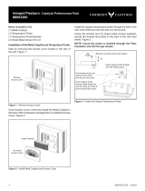
C. Installing Optional Catalyst & Performance
Pack (Part #0003260)
1. Locatetheaccesscoverpositionedattherearcenterof
theunit.(Figure5.6)
2. Removetheaccesscoverbypullingstraightupandout.
(Figure5.7)
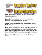
3. Installthecatalystbygentlyplacingitintothecavityand
straightdown,(Figure5.8).Placethecatalystwherethe
catalyst’s ceramic components will not be damaged.
Figure 5.6-Locateaccesscover.
Access Cover
Remove
Access Cover
Figure 5.7-Removeaccesscover.
Handle
Handle
Holder
Shield
Position
Figure 5.5-Handleholderandheatshieldpositions.
Storing the Handle
Usetheremovablehandletoopenorclosethedoors.After
usingit,removethehandlesoitwillnotgethot.Storethe
handle in the handle holder installed behind the right front
leg.(Figure5.5)
CatalystInstalled
Figure 5.8-Removecatalyst.
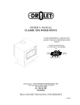
Attach the Catalyst Temperature Probe
Ifthecatalyticperformancepackhasbeenpurchased,install
the catalyst temperature probe into the cast iron wall behind
therearshieldasshown(Figure5.9)usetwo#10sheetmetal
screwsandbracketsupplied,securethebracketandprobe
tothebackofyourstove.(Figure5.9)
Figure 5.9-InstalltheCatalystTemperatureProbe
1.4"
1.8"
Bracketmountingscrewholelocation
Foldbracketstrapover
catalyst probe shaft
and secure with screw.
Insertcatalystprobe
throughsheet-metaland
castironbackandtwist&
pushthroughberpanel.
Insertcatalystprobebracket
withself-drillingscrew.

Vermont Castings • Intrepid FlexBurn
®
Installation Manual_R15 • 2018 - ___ • 09/2020 3-90-30007345i
D. Smoke and CO Detectors & Safety Tips
Smoke and CO Detectors
The use of smoke and carbon monoxide (CO) detectors
throughout the home is strongly advised, even if not
required by building codes or insurance regulations.
It is a good idea to install a smoke detector in the living
areas and each bedroom. Follow the smoke/CO detector
manufactures placement and installation instructions and
maintain regularly.
You may not, however, wish to install a detector in the
immediate vicinity of the stove. Depending on the sensitivity
oftheunit,thealarmcanbesetowhileyouaretending
thereoremptyingtheashes.Ifyouinstalladetectorinthe
same room, locate it as far away from the stove as possible.
Safety Tips
Convenientlylocatea“ClassA”reextinguishertocontend
with small res. Be sure the re extinguisher works and
is clearly visible.All occupants ofthehouseshould know
whereitis,andhowitoperates.Haveheavystovegloves
availablenearthestove.Have special safety accessories
(e.g.,ChildGuardScreen)availableforuseifsmallchildren
will be in the home.
Intheeventofastovepipeorchimneyre….
• Evacuatethehouseimmediately
• Notifytheredepartment
• If the re isn’t toothreatening, closing down the stove
tight,(damper,primaryair,alldoors)willhelptosmother
there.
• Inspect your stove, vent pipe and chimney for any
damage caused by the re and correct any damage
before using your stove again.
Fire Risk
• Donotleavethere unattendedwhenthe
door is unlatched
• Operateonlywithfrontdoorsandashpan
door closed.
• Unstablerewoodcouldfalloutoftherebox
creatingarehazardtoyourhome.
WARNING
!
/