EngA CRD-200 C-TRAC3 Operating instructions
- Category
- TVs & monitors
- Type
- Operating instructions

A
Sep 06
INSTALLATION AND OPERATION
MANUAL
FOR
CRD-200
C-TRAC3 REMOTE DISPLAY
UNIT MODEL NO. _________________
UNIT SERIAL NO. _________________
SERVICED BY: ___________________
TEL. NO: ________________________
CANADIAN
HEAD OFFICE
AND FACTORY
USA
HEAD OFFICE
AND FACTORY
CANADIAN
EASTERN FACTORY
1401 HASTINGS CRES.
SE
CALGARY, ALBERTA
T2G 4C8
Ph: (403) 287-4774
Fx: 888-364-2727
32050 W. 83rd STREET
DESOTO, KANSAS
66018
Ph: (913) 583-3181
Fx: (913) 583-1406
1175 TWINNEY DRIVE
NEWMARKET, ONTARIO
L3Y 5V7
Ph: (905) 898-1114
Fx: (905) 898-7244
www.engineeredair.com
SALES OFFICES ACROSS CANADA AND USA
Retain instructions with unit and maintain in a legible condition.
Please give model number and serial number when contacting
factory for information and/or parts.

A CRD-200
2 of 14 Sep 06
CRD-200
If any errors or omissions are noted please contact Engineered Air – Calgary Service at (403)
287-4775 or Fax (403) 287-4799.
To ensure warranty is honored, only a qualified HVAC service person, who has received
training on the CRD-200 and C-TRAC3, should be employed for service and troubleshooting.
If further information is required please contact the nearest Engineered Air office.
Under no conditions (except for temporary copying) should the unit function be removed
from the unit. There are two copies provided with the unit. One is in an envelope for copying,
then return it to the unit or store in a safe place. The other is attached to the control panel
door and should never be removed.
This manual is intended to be used in conjunction with the C-TRAC3 Operation, Installation
and Maintenance manual, and the unit function sheet.90

A CRD-200
3 of 14 Sep 06
Table of Contents
Introduction .....................................................................................................................................5
Wiring..............................................................................................................................................5
Display Description .........................................................................................................................6
CRD-200 Operation ........................................................................................................................ 6
Field Wiring Diagram.......................................................................................................................7
Page Description.............................................................................................................................8
Page 1 – Unit Operation.................................................................................................................. 9
Page 2 – Discharge Air ................................................................................................................... 9
Page 3 - Heating ............................................................................................................................. 9
Page 4 - Cooling ............................................................................................................................. 9
Page 5 - Economizer....................................................................................................................... 9
Page 6 – Digital Inputs.................................................................................................................. 10
Page 7 – 2nd Discharge Air............................................................................................................ 10
Page 8 – Ambient And Vfd............................................................................................................ 10
Page 9 – Function Type ................................................................................................................ 10
Page 10 – Save Setpoints............................................................................................................. 11
Page 11 – Unit On/Off................................................................................................................... 11
Page 12 – Low Limit...................................................................................................................... 11
Page 13 – Sensor Failure.............................................................................................................. 11
Page 14 – Heat Alarms ................................................................................................................. 11
Page 15 – Special Alarms............................................................................................................. 12
Page 16 – Reset ........................................................................................................................... 12
Points List......................................................................................................................................13

A CRD-200
4 of 14 Sep 06
DELESC ENTER
g
Ma e l i s
MOD

A CRD-200
5 of 14 Sep 06
INTRODUCTION
The Engineered Air CRD-200 remote display panel is designed to monitor and control
C-TRAC3 equipment operations via Modbus communication.
CRD-200 Command Capabilities
- Quickly identify the current operation of the equipment.
- Ability to scroll to the page associated with specific unit operations, e.g. Cooling
information.
- Alarm identification and associated alarm status.
- Adjustment of manual setpoints, e.g. minimum outside air.
- Enable or disable equipment operation.
The CRD-200 panel can be ordered with the following options:
Option 1: Display only
Option 2: Unit on/off switch.
Option 3: Unit on/off/auto switch c/w internal time clock.
Option 4: Unit occupied/unoccupied/off switch c/w internal time clock.
WIRING
The RS-485 communication cable from the CRD-200 to the C-TRAC3 is 24awg shielded
twisted pair (STP) with a shunt capacitance of 16pF per foot and 100 ohm characteristic
impedance. Category 5 cable can be used as defined by the EIA/TIA/ANSI 568 specification.
An additional set of 24VAC wires is required to power the remote panel. Refer to the table
below for minimum wire size and maximum distance to the remote panel.
Distance <100ft. <150ft. <200ft. <300ft. <350ft. <450ft.
AWG # #20 #20 #20 #18 #18 #16

A CRD-200
6 of 14 Sep 06
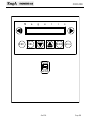
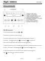
DISPLAY DESCRIPTION
CRD-200 Operation
To move between pages press either or .
To escape from modifying an entry press .
To modify a manual value, move to the page that allows manual changes to
the setpoint. Press and then press to decrease and to increase the
value. When the appropriate value has been set, press to save.
To ensure the value is not lost in the event of a power failure or equipment servicing, be sure
to save it. Go to page 10 and press then for yes, then press to save.
To restart the equipment from the CRD-200 go to page 16 and press then
press , then press to restart the equipment.
ENTER
ESC
MOD
MOD
ENTER
ENTER
MOD

A CRD-200
7 of 14 Sep 06
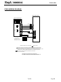
FIELD WIRING DIAGRAM
3
B-
A+
C
T1 RJ45
2
CAT 5 CABLE
CRD-200 REMOTE PANEL
ENTER
ESC DEL MOD
EAM G L SI
ON
OFF
SWITCH
HEAT OR COOL
UN
I
T
C
O
N
TRO
L
P
AN
E
L
24VAC
MAXIUM FIELD PANEL DISTANCE FOR 18 AWG WIRE IS350 FTOR
MAXIMUM CONTROL CIRCUIT AMPACITY AMPS AT24 VAC
CATEGORY 5CABLE AS DEFINED BY THE EIA/TIA/ANSI 568 SPECIFICATION IS24AWG
3. ALL WIRING TO COMPLY WITH THE CANADIAN ELECTRICAL CODE.
2. ALL WIRING SHOWN SHALL BE COMPLETED BY INSTALLER.
1. FIELD WIRING VOLTAGE DROP NOT TO EXCEED 8%.
7
6
24VAC
24VAC
24VAC
B-
A+
C
21 4
3 65 8
7
RJ45
2
14
3 65 8
7
N
G
D
A
+B
-
PIN OUTS
BLUE WIRE = #4 PIN
BROWN WIRE = #5 PIN
GREEN WIRE = #8 PIN
CAT 5 WIRE
T1 LEGEND TO C-TRAC
SHIELDED TWISTED PAIR (STP) WITH A SHUNT CAPACITANCE OF 16 pF PER FOOT
AND 100 OHM CHARACTERISTIC IMPEDANCE FOR RS-485COMMUNICATIONTO THE C-TRAC
ON
OFF
450 FT FOR 16 AWG WIRE.
H
N
2
1
CAT 5 CABLE
(ONLYONE CAT 5 CABLE IS CONNECTED, EITHER A.B.C. CABLE OR RJ45 CABLE)
84
123 567

A CRD-200
8 of 14 Sep 06
PAGE DESCRIPTION
The status information that can be viewed on each page is dependent on the type of
equipment being operated and the current status of the equipment. For example, a make-up
air unit will not have any economizer information.
The CRD-200 can be enabled to allow for the adjustment of setpoints, such as the discharge
air temperature, or the outside air damper minimum position.
Every CRD-200 is preprogrammed with the following information. The LCD will display this
information on display pages and each page is designed to provide the correct state of
operations.
1 Unit Operation
2 Discharge air
3 Heating
4 Cooling
5 Economizer
6 Digital Inputs
7 2nd Discharge air
8 Ambient and VFD
9 Function type
10 Save to Flash
11 Unit on/off
12 Low Limit
13 Sensor Failure
14 Heat Alarms
15 Special Alarms
16 Reset Unit

A CRD-200
9 of 14 Sep 06
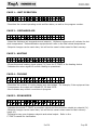
PAGE 1 – UNIT OPERATION
E
n
g
A
F
A
N
D
E
L
A
Y
O
N
<
#
0
1
H
T
G
M
O
D
E
>
-Describes the current operating mode and fan status, as well as the program number.
PAGE 2 – DISCHARGE AIR
2
D
I
S
A
I
R
=
6
5
o F
<
A
D
J
S
E
T
P
T
=
7
0
>
-Notes the discharge air temperature and setpoint. Multizone equipment will indicate the hot
deck temperature. Dehumidification equipment will refer to the final reheat temperature.
-Setpoint changes can be made here, but will not be saved unless saved to flash memory.
PAGE 3 - HEATING
3
H
T
G
=
8
7
%
<
M
A
I
N
H
E
A
T
O
N
>
-Shows the actual heating signal output (%) from the C-TRAC3 to the heating device.
-Indicates the return signal to confirm heating is operational.
PAGE 4 - COOLING
4
C
L
G
=
3
3
%
<
C
Y
C
L
I
N
G
O
N
>
-Describes the number of cooling stages as a percentage. For example, if the equipment has
3 compressors the output will indicate 33, 66 and 100%.
-Also indicates any control corrections in progress.
PAGE 5 - ECONOMIZER
5
E
C
O
N
=
7
0
%
<
A
D
J
M
I
N
P
O
S
=
1
0
%
>
-Indicates the actual C-TRAC3 economizer output and the minimum outside air setpoint (%).
-Setpoint changes can be made here, but will not be saved unless saved to flash memory
(page 10).
-Deviations may occur between setpoint and actual output. Refer to the
C-TRAC3 manual for clarification.

A CRD-200
10 of 14 Sep 06
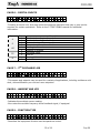
PAGE 6 – DIGITAL INPUTS
6
D
I
G
I
T
A
L
I
N
P
U
T
S
<
A
1
E
0
H
S
1
F
S
1
K
1
>
-Primarily a service tool, this page notes the external interlocks that may or may not be
required for certain operations. Refer to the C-TRAC3 OI&M manual for additional
information.
Input Status
Description
1 Mechanical cooling is allowed
A 0 Mechanical cooling is disabled
1 Economizer to minimum position
E 0 Economizer allowed to modulate
1 Heating is allowed
HS 0 Heating is disabled
1 Occupied mode
FS 0 Unit off
1 Unoccupied mode
K 0 Unit off
PAGE 7 – 2ND DISCHARGE AIR
7
C
O
L
D
D
E
C
K
=
6
5
o F
<
A
D
J
S
E
T
P
T
=
5
0
>
-This sensor and setpoint may be used for a variety of applications, including multizone cold
deck, dehumidification pre-cool and room setpoints.
PAGE 8 – AMBIENT AND VFD
8
A
M
B
I
E
N
T
=
6
5
o F
<
V
F
D
=
3
5
%
>
-Indicates the ambient sensor reading.
-Also notes the variable frequency drive feedback signal, if equipped.
PAGE 9 – FUNCTION TYPE
9
F
U
N
C
T
I
O
N
=
S
T
D
H
V
A
C
<
T
E
M
P
B
Y
=
B
M
S
R
E
S
E
T
>
-Describes the equipment function and temperature control.

A CRD-200
11 of 14 Sep 06
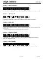
PAGE 10 – SAVE SETPOINTS
1
0
S
A
V
E
S
E
T
P
O
I
N
T
S
<
?
>
-Location to save any setpoint changes made to the C-TRAC3 into permanent flash memory.
PAGE 11 – UNIT ON/OFF
1
1
U
N
I
T
O
N
/
O
F
F
<
O
N
>
-If enabled, this page will allow the user to enable or disable equipment operation.
PAGE 12 – LOW LIMIT
1
2
L
O
W
L
I
M
I
T
O
K
<
S
E
T
P
T
=
4
0
o F
>
-The low limit, or freeze protection, setpoint is preprogrammed and cannot be changed from
the CRD-200.
-This page indicates the low limit setpoint and alarm indication.
PAGE 13 – SENSOR FAILURE
1
3
T
E
M
P
S
E
N
S
O
R
S
O
K
<
>
-If any of the 2 or 3 sensors used by the C-TRAC3 exceed the predetermined resistance
range, and alarm is indicated.
PAGE 14 – HEAT ALARMS
1
4
H
E
A
T
A
L
A
R
M
<
F
L
A
M
E
F
A
I
L
>
-Used to provide feedback regarding gas-fired and electric heating operational issues.

A CRD-200
12 of 14 Sep 06
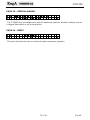
PAGE 15 – SPECIAL ALARMS
1
5
S
P
E
C
I
A
L
A
L
A
R
M
<
A
I
R
F
L
O
W
>
-The C-TRAC3 may be configured to allow for additional inputs for external contacts, such as
a clogged filter switch or air proving switch.
PAGE 16 – RESET
1
6
R
E
S
E
T
<
?
>
-This input will allow the user to reset and restart equipment operation.

A CRD-200
13 of 14 Sep 06
POINTS LIST
FAN ON
FAN OFF
FAN DELAY ON
FAN DELAY OFF
UNOCCUPIED FAN ON
UNOCCUPIED FAN OFF
CLG MODE
HTG MODE
ECON MODE
DEHUM MODE
MZONE MODE
Page 1
Unit Operation
NO MODE
DIS AIR = °F
HOT DECK = °F
SET PT =
Page 2
Discharge Air
ADJ SET PT =
NO HTG
HTG = %
Page 3
Heating
MAIN HEAT ON
NO CLG
CLG = %
CYCLING ON
Page 4
Cooling
CYCLING OFF
NO ECON
ECON = V
MIN POS = %
Page 5
Economizer
ADJ MIN POS = %
A
E
HS
FS
Page 6
Digital Inputs
K
NOT USED
COLD DECK = °F
PRECOOL = °F
ROOM = °F
SP MANUAL =
Page 7
2nd Discharge Air
SET POINT =
AMBIENT = °F Page 8 Ambient and VFD VFD = %

A CRD-200
14 of 14 Sep 06
ROOM STAT
ROOM RESET
BMS RESET
AMB RESET
SP + SP
BMS + SP
BMS + BMS
AMB + AMB
Temperature by
AMB + BMS
MUA
STD HVAC
MULTIZONE
Page 9
Function
DEHUMID
? Page 10 Save Setpoints YES
On Page 11 Unit On/Off Off
LOW LIMIT OK
LOW LIMIT ALARM
Page 12
Low Limit
SET POINT = °F
TEMP SENSORS OK
DIS FAILED
AMB FAILED
Page 13
Sensor Failure
SEC FAILED
NONE
PREPURGE
FLAME FAIL
HEAT FAIL
WIRE ERR
Page 14
Heat Alarms
FL RELAY
NONE
FILTER
Page 15
Special Alarms
AIR FLOW
?
Page 16 Reset Unit YES
-
 1
1
-
 2
2
-
 3
3
-
 4
4
-
 5
5
-
 6
6
-
 7
7
-
 8
8
-
 9
9
-
 10
10
-
 11
11
-
 12
12
-
 13
13
-
 14
14


EngA CRD-200 C-TRAC3 Operating instructions
- Category
- TVs & monitors
- Type
- Operating instructions
Ask a question and I''ll find the answer in the document
Finding information in a document is now easier with AI
Other documents
-
Reznor RDDA User manual
-
Johnson Controls GVC Series Start-Up & Operation
-
Reznor RECB User manual
-
McQuay WDG series User manual
-
Reznor YDSA User manual
-
Greenheck Microprocessor Controller Reference guide
-
-
McQuay MicroTech III RDT Operation and Maintenance Manual
-
 Chroma 63610-80-20 Operation & Programming Manual
-
