Page is loading ...

Form 100.210-IOM (FEB 2015)
INSTALLATION - OPERATION - MAINTENANCE
File: SERVICE MANUAL - Section 100
Replaces: 100.210-IOM (SEP 2012)
Dist: 3, 3a, 3b, 3c
Revised: July 2017
THIS MANUAL CONTAINS RIGGING, ASSEMBLY, START-UP,
AND MAINTENANCE INSTRUCTIONS. READ THOROUGHLY
BEFORE BEGINNING INSTALLATION. FAILURE TO FOLLOW THESE
INSTRUCTIONS MAY RESULT IN PERSONAL INJURY OR DEATH,
DAMAGE TO THE UNIT, OR IMPROPER OPERATION.
700 (60 Hz) / 572 (50 Hz) Horsepower
912 (60 Hz) / 752 (50 Hz) Horsepower
Please check www.johnsoncontrols.com/frick for the latest version of this publication.

100.210-IOM (FEB 2015)
Page 2
VYPER™ VARIABLE SPEED DRIVE
INSTALLATION - OPERATION - MAINTENANCE
TABLE OF CONTENTS
PREFACE
INTRODUCTION .............................................................................4
JOB INSPECTION ...........................................................................4
TRANSIT DAMAGE CLAIMS ...........................................................4
UNIT IDENTIFICATION ....................................................................4
FRICK VYPER™ MODEL NUMBER
DEFINITIONS/NOMENCLATURE ...................................................4
MODEL DESCRIPTIONS .................................................................. 5
VYPER PRE-INSTALLATION SITE CHECK LIST ................................6
VYPER PRE-OPERATION SITE CHECK LIST ....................................6
PRE-STARTUP INSPECTION ........................................................... 7
VYPER™ SYSTEM OVERVIEW
VYPER™ COMPONENT DESCRIPTION ............................................. 8
HARMONIC FILTER ....................................................................... 11
GENERAL OPERATION DESCRIPTION ........................................... 15
ELECTRICAL LIMITS ..................................................................... 15
CURRENT LIMITS ....................................................................... 15
INPUT SHORT CIRCUIT LIMITS ..................................................... 15
INSTALLATION
RIGGING AND HANDLING ............................................................. 17
UNIT (WITH FILTER) WEIGHTS (lb) ............................................. 17
VYPER™ MOUNTING CONFIGURATIONS ....................................... 17
PACKAGE MOUNTED UNITS ...................................................... 17
REMOTE MOUNTED UNITS ........................................................ 17
ENVIRONMENT ............................................................................19
VYPER™ COOLING CONFIGURATION ............................................ 19
VYPER™ COOLING LOOP.............................................................. 19
COOLANT TEMPERATURE LIMITS ................................................ 20
GENERAL COOLING SYSTEM REQUIREMENTS .............................20
WATER RECOMMENDATIONS ....................................................20
GLYCOL RECOMMENDATIONS ...................................................20
HEAT EXCHANGER PRES. DROP 912/752 & 700/572 MODELS ...... 21
PROPER INSTALLATION OF ELECTRONIC EQUIPMENT .................23
WIRE SIZING ................................................................................23
VOLTAGE SOURCE ....................................................................... 23
GROUNDING ................................................................................24
VFD APPLICATIONS .....................................................................24
CONDUIT ..................................................................................... 25
WIRING PRACTICES ....................................................................25
COMMUNICATIONS .....................................................................26
UPS POWER AND QUANTUM™ PANELS ......................................27
ELECTRICAL WIRING CONDUIT .................................................... 28
TRANSFORMERS .........................................................................28
POWER FACTOR CAPACITORS ....................................................28
SOFT-START SEQUENCE .............................................................28
INTERFERENCE WITH ELECTRONIC
EQUIPMENT .............................................................................. 29
INTERFACING ELECTRICAL EQUIPMENT .......................................29
SYSTEM OPERATING CONDITIONS .............................................. 29
PNEUMATIC CONTROLS ..............................................................29
VYPER™ PREINSTALLATION SITE CHECKLIST ............................... 29
VYPER™ POWER AND CONTROL ENTRY LOCATIONS ..................30
EXTERNAL POWER AND CONTROL WIRING ................................ 31
INPUT POWER CONNECTION .................................................... 31
OUTPUT POWER CONNECTION (REMOTE MOUNT) .................. 32
OUTPUT POWER CONNECTION (PACKAGE MOUNT) ................. 32
VYPER™ WIRING AND WIRING DIAGRAMS ...................................33
QUANTUM™LX COMMUNICATIONS WIRING ............................... 33
MOTOR THERMAL PROTECTION OPTIONS ................................ 33
VYPER™ PRE-OPERATION SITE CHECKLIST .................................36
BLOWER MOTOR ROTATION........................................................37
COOLANT CONTAMINATION AND PROPERTIES ...........................37
ADDING AND REPLACING COOLANT ...........................................38
OPERATION
QUANTUM™LX CONTROL PANEL .................................................41
VYPER™ OPERATION ...................................................................41
QUANTUM™LX PANEL SETUP ......................................................42
ACCESSING THE VYPER™ SETUP .................................................42
SETTING USER LEVEL ................................................................ 43
CONFIGURING COMPRESSOR OPERATION ................................44
PROGRAMMING VYPER™ / QUANTUM™LX COMMUNICATIONS 45
PROGRAMMING PID SETUP ....................................................... 46
THE VYPER™ AND HARMONIC FILTER SCREENS ........................ 47
VYPER SCREEN SETPOINTS ......................................................48
HARMONIC FILTER SCREEN .......................................................49
PROGRAMMING THE MOTOR SCREEN .......................................50
HIGH MOTOR AMP LIMIT EXAMPLES .................................... 51
VFD SETPOINTS .................................................................... 52
CAPACITY CONTROL SETPOINTS .......................................... 53
VFD SKIP FREQUENCIES ........................................................ 53
SUGGESTED VFD AND CAPACITY CONTROL SETTINGS ........ 53
COMPRESSOR SAFETIES SCREEN ......................................... 55
VSD LOGIC BOARD SETUP .......................................................... 57
SETTING THE JOB FLA ................................................................58
MOTOR ROTATION ......................................................................58
MAINTENANCE
NORMAL MAINTENANCE OPERATIONS ....................................... 61
STANDARD MAINTENANCE .......................................................61
VYPER™ POWER MODULE REPLACEMENT ................................... 61
VYPER™ HARMONIC FILTER POWER MODULE REPLACEMENT .....62
FREQUENTLY ASKED QUESTIONS ...............................................63
VYPER™ ALARMS / SHUTDOWNS ................................................64
OVERVIEW ................................................................................64
QUANTUM™LX LOAD INHIBIT, FORCE UNLOAD MESSAGES .........64
FAULT CODE DESCRIPTIONS ........................................................65
FRICK VYPER™ FAULT CODE LIST ................................................65
RECOMMENDED SPARE PARTS - 700/572 HP & 912/752 HP ........ 74
INDEX
Indicates an imminently hazardous situation which, if not avoided, will result in death or serious
injury.
Indicates a potentially hazardous situation or practice which, if not avoided, will result in death or
serious injury.
SAFETY PRECAUTION DEFINITIONS
Indicates a potentially hazardous situation or practice which, if not avoided, will result in damage
to equipment and/or minor injury.
Indicates an operating procedure, practice, etc., or portion thereof which is essential to highlight.
WARNING
CAUTION
DANGER
NOTICE

100.210-IOM (FEB 2015)
Page 3
VYPER™ VARIABLE SPEED DRIVE
INSTALLATION - OPERATION - MAINTENANCE
Figure 1 – Vyper™ Data Plate .........................................................4
Figure 2A - Vyper™ Elementary Wiring Diagram ...........................9
Figure 2B - Vyper™ Elementary Wiring Diagram ..........................10
Figure 3 - VSD Input Current Without Harmonic Filter ................ 12
Figure 4 - VSD Input Current With Harmonic Filter ..................... 12
Figure 5A - Harmonic Filter Elementary Wiring Diagram ............ 13
Figure 5B - Harmonic Filter Elementary Wiring Diagram .............14
Figure 6 - Vyper™ Package Mounted on Frick RWF II. ................. 17
Figure 7 - Vyper™ Cabinet and Stand ......................................... 18
Figure 8 - Minimum Flow Rates - WATER ...................................20
Figure 9 - Minimum Flow Rates - GLYCOL .................................. 21
Figure 10 - Pressure Drop vs. Flow Rate ..................................... 21
Figure 11 - Vyper™ P&I Diagram - Noneconomized .................... 22
Figure 12 - Vyper™ P&I Diagram - Economized ........................... 22
Figure 13 - Voltage Source Circuit For EMI Prevention ................ 23
Figure 14 - Control Power Ground Circuit ...................................24
Figure 15 - Motor And Starter Grounding ...................................24
Figure 16 - Separation Of Different Voltage Circuits ................... 25
Figure 17 - Electronic Control Panel Power Supplies ................... 26
Figure 18 - Vyper™ Cabinet Power and Control Entry Locations .. 30
Figure 19 - Vyper™ Input Power Terminal Connection Lugs ......... 31
Figure 20 - Insulation Stripped from Power Leads ...................... 31
Figure 21 - Fastening Power Leads ............................................. 31
Figure 22 - Ground Connection ................................................... 31
Figure 23 - Vyper™ Output Power Terminal Connection Lugs ...... 32
Figure 25 - Quantum™ LX Communications Terminal Block ......... 33
Figure 24 - Vyper™ Starter, Motor, Blower & Quantum Wiring .... 33
Figure 26 - Analog Board Wiring .................................................34
Figure 27 - Temperature Control Valve Wiring ............................ 34
Figure 28 - Thermistor Motor Protection Wiring ......................... 35
Figure 29 - RTD Motor Protection Wiring ................................... 35
Figure 30 - RTD Motor Protection Wiring ................................... 37
Figure 30a - RTD Motor Protection Wiring ................................. 37
Figure 31 - Blower Motor Nameplate .......................................... 37
Figure 32 - Coolant Circulation System ....................................... 38
Figure 33 - Removing the Cooling System Pipe Plug ...................38
Figure 34 - Hose connected to the Heat Exchanger Drain .........38
Figure 35 - Draining Coolant ......................................................38
Figure 36 - Relling the Cooling System ..................................... 39
Figure 37 - VSD Logic Board Connection J2 ................................ 39
LIST OF FIGURES
Figure 38 - Topping Off the Coolant Supply ................................ 39
Figure 39 - Installing the Cooling System Pipe Plug ....................39
Figure 40 - VSD Logic Board Connection J2 ............................... 39
Figure 41 - Quantum™LX Operating Status Screen...................... 42
Figure 42 - Quantum™LX Session Screen .................................... 43
Figure 43 - Quantum™LX Operating Status Screen ..................... 43
Figure 44 - Quantum™LX Compressor Conguration Screen ....... 44
Figure 45 - Communications Screen ...........................................45
Figure 46 - PID Setup Screen (Page 2) ........................................46
Figure 47 - Operating Values Menu .............................................47
Figure 48 - Pulldown for Vyper Screen .......................................47
Figure 49 - Vyper™ Screen ......................................................... 48
Figure 50 - Harmonic Filter Screen .............................................49
Figure 51 - Low Motor Amps.......................................................50
Figure 52 - Motor Screen ............................................................50
Figure 53 - High Motor Amps ...................................................... 51
Figure 54 - Ex.1 Motor Amps Safety Calculation Table ................ 51
Figure 55 - Ex. 1 Motor Amp Setpoint Calculations (Table A) ...... 51
Figure 56 - Ex. 2 Motor Amps Safety Calculation Table ............... 51
Figure 57 - Ex.2 Motor Amp Setpoint Calculations (Table B) ....... 51
Figure 58 - Ex. 3 Motor Amps Safety Calculation Table ............... 52
Figure 59 - Ex. 3 Motor Amp Setpoint Calculations (Table A) ...... 52
Figure 60 - Ex. 4 Motor Amps Safety Calculation Table .............. 52
Figure 61 - Ex. 4 Motor Amp Setpoint Calculations (Table B) ...... 52
Figure 62 - Motor Screen VFD Setpoints .................................... 52
Figure 63 - Motor Screen Capacity Control Setpoints ................. 53
Figure 64 - Example 1 VFD and Capacity Control Setpoints ........ 54
Figure 65 - 5:1 Turndown Suggested Control Strategy ................54
Figure 66 - Example 2 VFD and Capacity Control Setpoints ........ 55
Figure 67 - Compressor Safeties Screen ..................................... 55
Figure 69 - Example 2 VFD and Capacity Control Setpoints ........ 56
Figure 68 - 2:1 Turndown Suggested Control Strategy ................ 56
Figure 70 - Capacity Control Setpoints Screen............................ 57
Figure 71 - Vyper Logic Board ..................................................... 57
Figure 72 - Logic Board SW3 ....................................................... 57
Figure 73 - Vyper Logic Board ..................................................... 58
Figure 76 - Control Logic Board .................................................. 59
Figure 77 - Filter Logic Board ...................................................... 59
Figure 78 - Power Module Screw Tightening Sequence .............. 62
Figure 79 - Logic Board Test Button ............................................ 63
LIST OF TABLES
Table 1 – Supply Voltage Requirements ...................................... 15
Table 2 – Operating Voltage Limits ............................................. 15
Table 3 – Power Interruption Min. Voltage Limits ........................ 15
Table 4 – Unit Current Limits ....................................................... 15
Table 5 – Circuit Breaker Ratings and Lug Sizes .......................... 15
Table 6 – Ambient Temperature Operating Limits ....................... 19
Table 7 – Vyper™ Cabinet Component Temperature Thresholds .. 19
Table 8 – Entering Coolant Temperature Limits ........................... 20
Table 9 – Digital Control Signal Wire Recommendations .............28
Table 10 – Recommended Transformer Sizes .............................. 28
Table 11 – Vyper™ Output Power Lead Torque Specications ...... 32
Table 12 – Comm1 Setpoints ....................................................... 45
Table 13 – PID Channel #5 Setpoints ........................................... 46
Table 14 – Binary Parameter Indicator Status .............................48
Table 15 – Applied Motor FLA Calculation ...................................50
Table 16 – High Motor Amps Safety Calculation .......................... 50
Table 17 – High Motor Amp Setpoint Calculations (Table A) ........ 51
Table 18 – High Motor Amp Setpoint Calculations (Table B) ........ 51
Table 19 – Limit Calculations ....................................................... 58
Table 20 - Fault Code List ........................................................... 65

100.210-IOM (FEB 2015)
Page 4
VYPER™ VARIABLE SPEED DRIVE
INSTALLATION - OPERATION - MAINTENANCE
PREFACE
INTRODUCTION
This manual has been prepared to acquaint the owner and
service personnel with the INSTALLATION, OPERATION, and
MAINTENANCE procedures as recommended by Johnson
Controls-Frick for the Frick Vyper™ Variable Speed Drive unit.
For information about the functions of the Quantum™LX
Control panel, communications, specications, and wiring
diagrams, please see the applicable and most current Frick
documentation.
It is most important that these units be properly applied to
an adequately controlled refrigeration system. Consult an
author ized Johnson Controls-Frick repre sentative for expert
guidance in this determination.
Proper performance and continued satisfaction with the Frick
Vyper™ is dependent upon the following:
• Correct unit installation
• Correct utilization and operation of the unit in accordance
with the procedures detailed in Frick manuals.
• Regular and proper unit maintenance.
To ensure correct installation and application, the equipment
must be properly selected and connected to a properly de-
signed and installed system. The engineering plans, piping
layouts, etc. must be detailed in accordance with the best
practices and local codes, such as those outlined in ASHRAE
literature.
NOTICE
The Frick Vyper™ is a sophisticated piece of electronic
control equipment. All safety precautions consistent
with operation of high current and voltage electrical
equipment should be strictly enforced.
JOB INSPECTION
Immediately upon arrival of the unit, examine all crates,
boxes, and exposed compressor and component surfaces
for damage. Unpack all items and check against shipping
lists for any possible shortage. Examine all items for damage
from unit transit.
TRANSIT DAMAGE CLAIMS
All claims must be made by consignee. This is an ICC re-
quirement. Request immediate inspec tion by the agent of
the carrier and be sure the proper claim forms are executed.
Contact the Sales Administration Depart ment in Waynesboro,
PA to report dam age or shortage claims. Damage must be
photographically documented.
UNIT IDENTIFICATION
DANGER
Shock Hazard! Wait ve (5) minutes after switching OFF
power to the Vyper™ to allow capacitors in the cabinet
to discharge before opening the cabinet door.
FAILURE TO DO SO WILL RESULT IN DEATH OR
SERIOUS INJURY.
Each Vyper™ has a unit identication label located on the
right side of the cabinet. The data plate contains the Frick
Part Number, the unique Serial Number, and the basic Model
Number for the unit. In addition, the data label also has elec-
trical information pertinent to the individual unit.
NOTICE
When inquiring about the Vyper™ or ordering spare
parts, please provide the MODEL Number and SERIAL
Number from the data plate.
Figure 1 – Vyper™ Data Plate
FRICK VYPER™ MODEL NUMBER
DEFINITIONS/NOMENCLATURE
VYE_RHFL_46
Input Voltage - 46 (460V)
- 50 (400V)
Oil Pump - Large HP (L)
- Small HP (S)
IEEE 519 Filter - Installed (F)
- No Filter
(Blank)
Cooling Method - Water (H)
- Liquid (G)
Mounting - Package (P)
- Remote (R)
Drive Type - VYE 700 HP
- VYF 572 HP
- VYG 912 HP
- VYH 752 HP

100.210-IOM (FEB 2015)
Page 5
VYPER™ VARIABLE SPEED DRIVE
INSTALLATION - OPERATION - MAINTENANCE
MODEL DESCRIPTIONS
These tables provide the model number, Frick part number and basic description of each Vyper™ Drive covered in this manual.
Model No. Frick P/N Description
VYE_PH_S-46 720C0168G01 700 HP, Water Cooled, 460 Volts, Package Mount, 3 HP Oil Pump
VYE_PH_M-46 720C0168G02 700 HP, Water Cooled, 460 Volts, Package Mount, 5 HP Oil Pump
VYE_PH_L-46 720C0168G03 700 HP, Water Cooled, 460 Volts, Package Mount, 7.5 HP Oil Pump
VYE_PHFS-46 720C0168G04 700 HP, Water Cooled, w/ Filter, 460 Volts, Package Mount, 3 HP Oil Pump
VYE_PHFM-46 720C0168G05 700 HP, Water Cooled, w/ Filter, 460 Volts, Package Mount, 5 HP Oil Pump
VYE_PHFL-46 720C0168G06 700 HP, Water Cooled, w/ Filter, 460 Volts, Package Mount, 7.5 HP Oil Pump
VYE_RH_S-46 720C0168G07 700 HP, Water Cooled, 460 Volts, Remote Mount, 3 HP Oil Pump
VYE_RH_M-46 720C0168G08 700 HP, Water Cooled, 460 Volts, Remote Mount, 5 HP Oil Pump
VYE_RH_L-46 720C0168G09 700 HP, Water Cooled, 460 Volts, Remote Mount, 7.5 HP Oil Pump
VYE_RHFS-46 720C0168G10 700 HP, Water Cooled, w/ Filter, 460 Volts, Remote Mount, 3 HP Oil Pump
VYE_RHFM-46 720C0168G11 700 HP, Water Cooled, w/ Filter, 460 Volts, Remote Mount, 5 HP Oil Pump
VYE_RHFL-46 720C0168G12 700 HP, Water Cooled, w/ Filter, 460 Volts, Remote Mount, 7.5 HP Oil Pump
VYF_PH_S-50 720C0168G13 572 HP, Water Cooled, 400 Volts, Package Mount, 3 HP Oil Pump
VYF_PH_M-50 720C0168G14 572 HP, Water Cooled, 400 Volts, Package Mount, 5 HP Oil Pump
VYF_PH_L-50 720C0168G15 572 HP, Water Cooled, 400 Volts, Package Mount, 7.5 HP Oil Pump
VYF_PHFS-50 720C0168G16 572 HP, Water Cooled, w/ Filter, 400 Volts, Package Mount, 3 HP Oil Pump
VYF_PHFM-50 720C0168G17 572 HP, Water Cooled, w/ Filter, 400 Volts, Package Mount, 5 HP Oil Pump
VYF_PHFL-50 720C0168G18 572 HP, Water Cooled, w/ Filter, 400 Volts, Package Mount, 7.5 HP Oil Pump
VYF_RH_S-50 720C0168G19 572 HP, Water Cooled, 400 Volts, Remote Mount, 3 HP Oil Pump
VYF_RH_M-50 720C0168G20 572 HP, Water Cooled, 400 Volts, Remote Mount, 5 HP Oil Pump
VYF_RH_L-50 720C0168G21 572 HP, Water Cooled, 400 Volts, Remote Mount, 7.5 HP Oil Pump
VYF_RHFS-50 720C0168G22 572 HP, Water Cooled, w/ Filter, 400 Volts, Remote Mount, 3 HP Oil Pump
VYF_RHFM-50 720C0168G23 572 HP, Water Cooled, w/ Filter, 400 Volts, Remote Mount, 5 HP Oil Pump
VYF_RHFL-50 720C0168G24 572 HP, Water Cooled, w/ Filter, 400 Volts, Remote Mount, 7.5 HP Oil Pump
Model No. Frick P/N Description
VYG_PH_M-46 720C0169G01 912 HP, Water Cooled, 460 Volts, Package Mount, 5 HP Oil Pump
VYG_PH_L-46 720C0169G02 912 HP, Water Cooled, 460 Volts, Package Mount, 7.5 HP Oil Pump
VYG_PHFM-46 720C0169G03 912 HP, Water Cooled, w/ Filter, 460 Volts, Package Mount, 5 HP Oil Pump
VYG_PHFL-46 720C0169G04 912 HP, Water Cooled, w/ Filter, 460 Volts, Package Mount, 7.5 HP Oil Pump
VYG_RH_M-46 720C0169G05 912 HP, Water Cooled, 460 Volts, Remote Mount, 5 HP Oil Pump
VYG_RH_L-46 720C0169G06 912 HP, Water Cooled, 460 Volts, Remote Mount, 7.5 HP Oil Pump
VYG_RHFM-46 720C0169G07 912 HP, Water Cooled, w/ Filter, 460 Volts, Remote Mount, 5 HP Oil Pump
VYG_RHFL-46 720C0169G08 912 HP, Water Cooled, w/ Filter, 460 Volts, Remote Mount, 7.5 HP Oil Pump
VYH_PH_M-50 720C0169G09 752 HP, Water Cooled, 400 Volts, Package Mount, 5 HP Oil Pump
VYH_PH_L-50 720C0169G10 752 HP, Water Cooled, 400 Volts, Package Mount, 7.5 HP Oil Pump
VYH_PHFM-50 720C0169G11 752 HP, Water Cooled, w/ Filter, 400 Volts, Package Mount, 5 HP Oil Pump
VYH_PHFL-50 720C0169G12 752 HP, Water Cooled, w/ Filter, 400 Volts, Package Mount, 7.5 HP Oil Pump
VYH_RH_M-50 720C0169G13 752 HP, Water Cooled, 400 Volts, Remote Mount, 5 HP Oil Pump
VYH_RH_L-50 720C0169G14 752 HP, Water Cooled, 400 Volts, Remote Mount, 7.5 HP Oil Pump
VYH_RHFM-50 720C0169G15 752 HP, Water Cooled, w/ Filter, 400 Volts, Remote Mount, 5 HP Oil Pump
VYH_RHFL-50 720C0169G16 752 HP, Water Cooled, w/ Filter, 400 Volts, Remote Mount, 7.5 HP Oil Pump

100.210-IOM (FEB 2015)
Page 6
VYPER™ VARIABLE SPEED DRIVE
INSTALLATION - OPERATION - MAINTENANCE
Read This First
Vyper Pre-Installation and Pre-Operation Checklist
The following items MUST be checked and completed by the installer prior to the arrival of the Frick Field Service Supervisor.
Details on the checklist can be found in this manual. Certain items on this checklist will be re-veried by the Frick Field Service
Supervisor prior to the actual start-up.
Vyper Pre-Installation Site Check List
Before attempting to install a Vyper Drive system, please perform a site inspection to assure that the following requirements are
met. (Where Applicable)
-- Verify that the coolant (water or glycol) is available for the Vyper heat exchanger connections. Hard-pipe the coolant
supply in accordance to all local and national piping codes. Sufcient coolant ow and temperature levels must be
available to the Vyper VSD at installation. When hard-piping the coolant supply, take into consideration that room is
required in order to add coolant to the system.
-- Verify that the compressor package temperature sensors are RFI suppression type (639A0151G01).
-- Incoming power cables must enter through the access plate supplied on the top left side of the unit. This access plate
MUST BE removed, entry holes made in the plate, and then reinstalled. Power cables MUST BE in accordance with
local and national electrical codes and current safety standards. See “External Power And Control Wiring” in the
INSTALLATION section of this manual.
-- Verify that the power cable lengths from the Vyper to the compressor motor do not exceed 50 feet (15 meters) and the
location of the Vyper is suitable for mounting.
-- Verify that the motor is suitable for Inverter duty service: 20-100% Speed (12-60 hZ) or 50-100% (30-60 hZ) The motor
must have thermal protection per NEC 2005. (RTD, Thermostat, Thermistor).
-- Verify that the ambient temperature remains within the recommended operating range of 40-135°F (4-57°C). If the drive
is to operate below 40°F (4°C), provide enclosure ambient space heating.
-- Verify that all wiring is contained in metallic conduit. Use of PVC or other materials is not acceptable UNLESS shielded UL
rated power cable is used. Follow recommendations of “Proper Installation Of Electronic Equipment In An Industrial
Environment” in the INSTALLATION section of this manual.
-- Verify that all control power (120 VAC), communications / analog wiring, and 460 VAC power are in separate metallic
conduits. Properly shielded and grounded analog cables are not required to be in EMT.
Vyper Pre-Operation Site Check List
Prior to Quantum™LX setup and starting operation of the Vyper Drive system, review the following checklist to ensure all instal-
lation requirements are met. (Where Applicable)
-- Environmental:
A: Cleanliness – Keep panel doors closed and ensure that construction debris is kept out of the cabinet.
B: Use the conduit knockouts provided. Avoid metal shavings in the drive enclosure.
C: Clean out all debris with a low power magnet or a vacuum cleaner.
-- Mounting: Verify that the Vyper Drive is properly mounted: to the oor or wall for remote mounts or to the package for
package mounted units.
-- Verify that the primary water or glycol coolant supply is connected to the heat exchanger at the recommended ow and
temperature recommendations.
-- Wiring (use “Proper Installation Of Electronic Equipment In An Industrial Environment” in the INSTALLATION section of
this manual as a guideline):
A: Wiring from the drive to the motor must be enclosed in a grounded metal conduit even if poured in a concrete oor.
Use of PVC or other materials is not acceptable UNLESS shielded UL rated power cable is used.
B: Separate grounded metal conduits must be provided for input power, output power, and control wiring. Failure to
provide separate conduits could result in disruption of other electrical devices due to harmonics and RFI / EMI gener-
ated in the drive.
C: Bond all conduit to the cabinet.
D: Protect control wires (analog and digital) from noise. Use properly shielded and grounded analog control wires. Digital
and analog control wiring must be separate from each other as well as separate from 3 phase control and power wir-
ing. Noisy input signals will cause erratic drive operation.
E: Verify control wiring has been connected from the Quantum™LX panel to the Vyper in accordance with the engineer-
ing drawings for the specic installation.
F: Verify power wiring has been connected at the correct connection points and properly seated in accordance with the
provided engineering drawings for the specic installation.
-- Drain the shipping coolant from the Vyper and properly dispose. Replace with running coolant (pink) and purge air from
the cooling system. Refer to “Replacing Coolant” in the OPERATION section of this manual.

100.210-IOM (FEB 2015)
Page 7
VYPER™ VARIABLE SPEED DRIVE
INSTALLATION - OPERATION - MAINTENANCE
-- Apply power to the Vyper Drive system.
A: Conrm dipswitches on the Vyper Logic Board are properly set. Refer to “VSD Logic Board Setup” in the OPERATION
section of this manual.
B: Verify no problems exist with the unit power supply connections.
C: Verify no problems exist with the boot-up of the Quantum™LX panel and control system.
D: Set the FLA ratings on the Vyper Logic Board as per job site requirements.
E: Set up the Quantum™LX panel in accordance with job site requirements. Refer to “Quantum™LX Panel Setup” in the
OPERATION section of this manual.
F: Conrm operation of internal cooling fans.
G: Conrm operation of the coolant pump.
H: Conrm operation of the Vyper motorized coolant temperature control mixing valve.
I: Conrm wiring, operation, and correct rotation of motor blower fans if present.
Pre-Startup Inspection
After installation is complete, use the following as guide to
checks items D – I, under in the Applying power to the Vyper™
Drive system section, in the preceding Vyper™ Pre-Operation
Site Checklist. Any changes to factory setpoints, needs to
be approved by Frick®. Failure to obtain approval may void
warranty. Read all steps thoroughly and contact the factory
with any questions before proceeding.
1. With power off - In the drive, remove wire 624 (com-
pressor run) on the drive side of control wiring terminal
strip.
2. Remove wire 675 (oil pump run) if the unit is equipped
with an oil pump.
3. Close the drive, turn on the disconnect using the operat-
ing handle on the door.
4. Once the Quantum™LX panel has booted go to the level
2 operating session.
5. Conrm communications between the Vyper™ drive
and the Quantum™LX by going to the Vyper™ screen.
If there are base-plate temperature readings that are
approximate to ambient and a value is displayed for the
JOB FLA communications is conrmed. Compare the Job
FLA value to the panel test report Special Instructions
section to ensure they match. If the JOB FLA is not listed
on the panel test report, use the JOB FLA tables in this
manual to calculate.
6. Go to the motor setpoints screen to check the motor
amps safeties, relative to the motor and drive combina-
tion. If these values are not correct use the tables in this
manual to calculate what they should be.
7. Verify proper operation of the motorized coolant mixing
valve on the back of the drive.
• Locate the Coolant mixing valve on the back of the
drive, remove the cover from the motor and check
that the dip-switches are set as 1 ON, 2 OFF, 3 ON
& 4 OFF. If a change needs to be made, the power
must be cycled at the panel for the change to be in
effect.
• Go to Page 2 of PID setpoints, for the Vyper Coolant
PID. Ensure the setup is per the setup in this manual.
If it is, set the Control as Always and the Direction
as Reverse. Check the indicator disc or arrow on
the shaft between the valve and the actuator motor
that it is operating. Once it has moved to one end of
the stroke, change the Direction back to Forward.
This should move the Indicator Disc or Arrow back
to the other end of the stroke.
• Set the Control back to Running and submit.
8. Using a screw driver at the operating handle on the
door, open the drive leaving the power on, so that the
ride side panel can be opened providing access to the
logic board.
9. Re-secure the left side panel.
10. If the Job FLA setting is not correct this can now be set
using the Job FLA pot on the control logic board. Moni-
tor the value on the Vyper screen of the Quantum™LX
to determine when the value is properly set.
11. Test the internal fan and coolant circulation pump op-
eration by removing the P2 plug from the J2 connector
on the control logic board. Removing this plug will start
these devices. You will hear the fans run. The circula-
tion in the coolant loop should be seen through the
clear hose, proving the circulation pumps operation.
Reconnect the P2 plug to the J2 connector to turn off
these devices. Doing this test will create a Low Inverter
Base-Plate Temperature shutdown on the Quantum™LX
that will need to be cleared.
12. Close the drive completely and with power still on, do a
simulated run of the compressor by pressing the manual
start button on the Quantum™LX. This should engage
the blower motors on the compressor drive motor to
verify proper rotation and operation of the blower mo-
tors. Rotational arrows on the fan housing shows proper
rotation, correct if necessary by changing any two wires
at the blower motor connection box with power locked
out.
13. Turn power off with the operating handle on the door
of the drive. Open the drive and check to ensure the
panel is de-energized. Carefully replace wires 624 and
675. Tighten to 12 lb. In.

100.210-IOM (FEB 2015)
Page 8
VYPER™ VARIABLE SPEED DRIVE
INSTALLATION - OPERATION - MAINTENANCE
VYPER™ SYSTEM OVERVIEW
VYPER™ COMPONENT DESCRIPTION
The Frick Vyper™ Variable Speed Drive is a liquid-cooled,
transistorized, PWM inverter in a highly integrated package.
This unit is factory designed to mount either remotely on a
stand or integrally to the compressor package. The power
section of the drive is composed of four major blocks:
• AC to DC rectier section with integrated precharge circuit
• DC link lter section
• Three-phase DC to AC inverter section
• Output suppression network
An electronic circuit breaker with ground fault sensing con-
nects the AC line to an AC line choke and then to the DC
converter. The line choke will limit the amount of fault current
so that the electronic circuit breaker is sufcient for protect-
ing the Vyper™ input fuses. See the elementary wiring diagram
in Figures 2A and 2B for wiring and component references.
The AC to DC Rectier utilizes a semi-converter formed by
the connection of three SCR/diode modules (1SCR-3SCR)
in a three phase bridge conguration (See Figure 2). The
modules are mounted on a liquid cooled heatsink. Use of
the semiconverter conguration permits implementation of
a separate precharge circuit to limit the ow of current into
the DC link lter capacitors when the drive is switched on
and it also provides a fast disconnect from the power mains
when the drive is switched off. When the drive is turned off,
the SCRs in the semiconverter remain in a nonconducting
mode and the DC link lter capacitors remain uncharged.
When the drive is commanded to run, a set of precharge re-
sistors (1RES, 2RES) are switched into the circuit by contactor
1M. The DC link lter capacitors are slowly charged via the
precharge resistors and the diodes of the semiconverter for
a xed time period of fteen (15) seconds. After the fteen-
second time period has expired, the SCR’s are gated fully on
and the contactor 1M is dropped out.
A “free-wheeling” diode (1CR) is included to reduce the surge
current which must be conducted through the semiconverter
if a serious fault occurs across the DC link. Three (3) power
fuses (1FU - 3FU) and an electronic circuit breaker (1SW)
with ground fault sensing connects the AC to DC converter
to the power mains. The drive utilizes very fast semicon-
ductor power fuses to ensure that the SCR/diode module
packages do not rupture if a catastrophic failure occurs on
the DC link. The SCR Trigger board (031-01472) provides the
gating pulses for the SCR’s as commanded by the VSD Logic
board (031-02506).
The DC Link Filter section of the drive consists of two ba-
sic components, a DC Link “smoothing” inductor or pair of
inductors (1L, 2L) and a series of electrolytic lter capacitors
(C1-C36). This inductor / capacitor combination forms a low-
pass L-C lter which effectively smooths the ripple voltage
from the AC to DC rectier while simultaneously providing a
large energy reservoir for use by the DC to AC inverter section
of the drive. In order to achieve a suitable voltage capability
for the capacitor portion of the lter; lter capacitor “banks”
are formed by connecting two capacitors in series to form a
“pair”, and then paralleling a suitable number of “pairs” to
form a capacitor “bank”. In order to assure an equal sharing
of the voltage between the series connected capacitors and
to provide a discharge means for the capacitor bank when
the VSD is powered off, “bleeder” resistors (3RES and 4RES)
are connected across the capacitor banks.
The DC to AC Inverter section of the VSD (See Fig. 2),
serves to convert the rectied and ltered DC back to AC
at the magnitude and frequency commanded by the VSD
Logic board. The inverter section is actually composed of
three identical inverter output phase assemblies. These as-
semblies are in turn composed of a series of Insulated Gate
Bipolar Transistor (IGBT) modules (Q1-Q4) mounted to a
liquid cooled heatsink, a lter capacitor “bank” (C13-C20)
and a VSD Gate Driver board (031-01681) which provides
the On and Off gating pulses to the IGBT’s as determined
by the VSD Logic board.
In order to minimize the parasitic inductance between the
IGBT’s and the capacitor banks, copper plates which electri-
cally connect the capacitors to one another and to the IGBT’s
are connected together using a “laminated bus” structure.
This “laminated bus” structure is a actually composed of
a pair of copper bus plates with a thin sheet of insulating
material acting as the separator/insulator. The “laminated
bus” structure forms a parasitic capacitor which acts as a
small valued capacitor, effectively canceling the parasitic
inductance of the busbars themselves. To further cancel the
parasitic inductances, a series of small lm capacitors (C43-
C51) are connected between the positive and negative plates
of the DC link. An IGBT driver “shield board” (031-01627),
mounted just beneath the VSD Gate Driver board, provides
electrical shielding for the Gate Driver board.
The VSD Output Suppression Network is composed of a
series of capacitors (C61-C66) and resistors (5RES-10RES)
connected in a three phase delta conguration. The param-
eters of the suppression network components are chosen
to work in unison with the parasitic inductance of the DC
to AC inverter sections in order to simultaneously limit both
the rate of change of voltage and the peak voltage applied
to the motor windings. Limiting the peak voltage to the
motor windings, as well as the rate-of-change of motor
voltage avoid problems commonly associated with PWM
motor drives, such as stator-winding end-turn failures and
electrical uting of motor bearings.
Various ancillary sensors and boards are used to convey
information back to the VSD Logic board. The following list
describes some of these components.
• Each liquid-cooled heatsink within the DC to AC inverter
section contains a thermistor heatsink temperature sensor
(RT1 - RT3) to provide temperature information to the VSD
logic board.
• The AC to DC semiconverter heatsink temperature moni-
tored using a thermistor temperature sensor (RT4).
• The bus isolator board (031-01624) utilizes three resistors
on the board to provide a “safe” impedance between the
DC link lter capacitors located on the output phase bank
assemblies and the VSD logic board. The bus isolator board
provides the means to sense the positive, midpoint, and
negative connection points of the VSD’s DC link.
• A Current Transformer (3T - 5T) is included on each output
phase assembly to provide motor current information to
the VSD logic board.

100.210-IOM (FEB 2015)
Page 9
VYPER™ VARIABLE SPEED DRIVE
INSTALLATION - OPERATION - MAINTENANCE
Figure 2A - Vyper™ Elementary Wiring Diagram
NOTE: Drawings for specic units can be found in the door of
the VyperTM Drive or check with Frick Engineering department.

100.210-IOM (FEB 2015)
Page 10
VYPER™ VARIABLE SPEED DRIVE
INSTALLATION - OPERATION - MAINTENANCE
Figure 2B - Vyper™ Elementary Wiring Diagram
NOTE: Drawings for specic units can be found in the door of
the VyperTM Drive or check with Frick Engineering department.

100.210-IOM (FEB 2015)
Page 11
VYPER™ VARIABLE SPEED DRIVE
INSTALLATION - OPERATION - MAINTENANCE
HARMONIC FILTER
The VSD system may include an harmonic lter designed to
meet the IEEE Std 519 -1992, “IEEE Recommended Practices
and Requirements for Harmonic Control in Electrical Power
Systems”. The lter is offered as a means to “clean up” the
input current waveform drawn by the VSD from the power
mains, thus reducing the possibility of causing electrical inter-
ference with other sensitive electronic equipment connected
to the same power source.
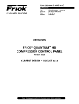
Figure 3 is a plot of the typical input current waveform for the
VSD system without the harmonic lter when the system is
operating at 50% load. Figure 4 is a plot of the typical input
current waveform for the VSD system with the harmonic lter
installed when operating at the same load conditions. The
plots show that the input current waveform is converted from
a square wave to a fairly clean sinusoidal waveform when the
lter is installed. In addition, the power factor of the system
with the harmonic lter installed corrects the system power
factor to nearly unity.
The power section of the Harmonic Filter is composed of four
major blocks: a precharge section, a “trap” lter network, a
three phase inductor and an IGBT Phase Bank Assembly. See
the elementary wiring diagram in Figures 5A and 5B for wiring
and component reference
The Precharge Section is formed by three resistors (11RES
- 13RES) and two contactors, the precharge contactor (2M),
and the supply contactor (3M). The precharge network serves
two purposes, to slowly charge the DC link lter capacitors
associated with the lter Phase Bank Assembly (via the
diodes within the IGBT modules Q13-Q18) and to provide a
means of disconnecting the lter power components from
the power mains. When the drive is turned off, both contac-
tors are dropped out and the lter phase bank assembly is
disconnected from the mains.
When the drive is commanded to run, the precharge resistors
are switched into the circuit via contactor 2M for a xed time
period of ve (5) seconds. This permits the lter capacitors
in the phase bank assembly to slowly charge. After the ve-
second time period, the supply contactor is pulled in and
the precharge contactor is dropped out, permitting the lter
phase bank assembly to completely charge to the peak of the
input power mains. Three power fuses (11FU -13FU) connect
the lter power components to the power mains. Very fast
semiconductor power fuses are utilized to ensure that the
IGBT modules do not rupture if a catastrophic failure occurs
on the DC link of the lter phase bank assembly.
The “Trap” Filter is composed of a series of capacitors
(C84-C92), inductors (4L-6L) and resistors (16RES-18RES).
The “trap” lter acts as a low impedance for a range of fre-
quencies centered at the PWM switching frequency of the
lter (20 kHz). The purpose of the trap is to block currents
at the switching frequency of the lter from getting onto
the power mains.
The Three-Phase Inductor provides some impedance for
the lter to “work against”. The inductor effectively limits
the rate of change of current at the input to the lter to a
reasonable level.
The IGBT Phase Bank Assembly is the most complicated
power component in the harmonic lter. The purpose of the
assembly is to generate harmonic currents required by the
drive’s AC to DC converter so that these harmonic currents
are not drawn from the power mains. The phase bank is
composed of a series of IGBT modules (Q13-Q18) mounted to
a liquid-cooled heatsink, a lter capacitor “bank” (C67-C76)
and an IEEE 519 Filter Gate Driver board (031-01786) which
provides the On and Off gating pulses to the IGBT’s as de-
termined by the 519 Filter Logic board. In order to assure an
equal sharing of the voltage between the series connected
capacitors on the lter bank, “bleeder” resistors 14RES and
15RES are connected across the banks. In order to counteract
the parasitic inductances in the mechanical structure of the
phase bank, the lter incorporates “laminated bus” technology
and a series of small lm capacitors (C77-C83). The technology
used is identical to that used in the VSD’s DC to AC inverter
section of the drive.
Various ancillary sensors and circuit boards are used to convey
information back to the harmonic lter logic board. The fol-
lowing list describes some of these components.
• A thermistor temperature sensor, RT5, is mounted onto the
liquid-cooled heatsink to provide temperature information.
• Current Transformers 6T and 7T sense the input current
drawn by the VSD’s AC to DC converter.
• DC Current Transformers (DCCT1 and DCCT2) sense the
current generated by the harmonic lter.
• The Line Voltage Isolation Board (031-02022) senses the
input voltage to the system, steps the voltage down to a
safe level and provides isolation between the Filter Logic
board and the power mains.
• The Bus Isolation Board (031-01624) incorporates three re-
sistors to provide a “safe” impedance between the DC lter
capacitors located on the phase bank assembly and the lter
logic board. The bus isolation board provides the means to
sense the positive, midpoint, and negative connection points
of the lter’s DC link.

100.210-IOM (FEB 2015)
Page 12
VYPER™ VARIABLE SPEED DRIVE
INSTALLATION - OPERATION - MAINTENANCE
Figure 3 - VSD Input Current Without Harmonic Filter
Figure 4 - VSD Input Current With Harmonic Filter

100.210-IOM (FEB 2015)
Page 13
VYPER™ VARIABLE SPEED DRIVE
INSTALLATION - OPERATION - MAINTENANCE
Figure 5A - Harmonic Filter Elementary Wiring Diagram
NOTE: Drawings for specic units can be
found in the door of the VyperTM Drive or
check with Frick Engineering department.

100.210-IOM (FEB 2015)
Page 14
VYPER™ VARIABLE SPEED DRIVE
INSTALLATION - OPERATION - MAINTENANCE
Figure 5B - Harmonic Filter Elementary Wiring Diagram
NOTE: Drawings for specic units can be
found in the door of the VyperTM Drive or
check with Frick Engineering department.

100.210-IOM (FEB 2015)
Page 15
VYPER™ VARIABLE SPEED DRIVE
INSTALLATION - OPERATION - MAINTENANCE
In addition, the drive is capable of operating without a load
for ease of service. Refer to Table 4 for current limits.
TABLE 4 – UNIT CURRENT LIMITS
HP Freq Voltage RMS current LRA max
912 HP 60 Hz 460V 1180A 7014A
752 HP 50 Hz 400V 1180A 8205A
700 HP 60 Hz 460V 880A 5777A
572 HP 50 Hz 400V 880A 5780A
The following information is also helpful in the operation
of the unit:
• Overload: 105% of full load rating for seven (7) seconds.
• Efciency: 98% Typical at rated load and frequency.
INPUT SHORT CIRCUIT LIMITS
Vyper™ drives are suitable for use on circuits capable of
delivering up to 100,000 RMS symmetrical amperes and a
maximum of 480 VAC.
The Vyper™ can be affected by specic events that can de-
crease product life and cause component damage related to
the input power conditioning. These events include:
• The power source experiences interruptions.
• The power system has power factor correction capaci-
tors switched in and out of the system by either the
power supplier or the end user.
• The power source contains voltage spikes which could
be caused by equipment on the same line or natural
phenomena such as electrical storms.
If one or more of these conditions exist, Frick recommends
that the end user install minimum impedance between the
Vyper™ and the power source. A transformer or other similar
device can supply the impedance.
A 100% rated input power circuit breaker with ground fault
protection and external lockable operator is supplied as
standard. The circuit breaker is sized in accordance with the
National Electrical Code or UL requirements. Refer to Table
5 for circuit breaker ratings and lug sizes.
TABLE 5 – CIRCUIT BREAKER RATINGS AND LUG SIZES
Horsepower Circuit Breaker
Rating (Amps)
Circuit Breaker
Lug Sizes
700/572 1000 3/0 to 500 KCMIL
912/752 1200 3/0 to 500 KCMIL
The maximum per phase Total Harmonic Distortion (THD)
of the input current shall not exceed 30% at 100% rated
power. The Frick® Vyper™ drive typically produces between
20-30% THD.
An IEEE 519 Harmonic Filter is required if the THD of the input
current at the installation cannot exceed 8%. The IEEE 519
Harmonic Filter is highly recommended for crucial applications
such as hospitals, computer networks, airports, etc.
GENERAL OPERATION DESCRIPTION
The Vyper™ serves as the motor starter and capacity control
for a Frick screw compressor. The Vyper™ controls capacity by
reducing compressor speed and optimizing the compressor
efciency at all loads.
The Vyper™ varies the screw compressor speed by control-
ling the frequency and voltage of electrical power supplied
to the compressor motor. Unlike general purpose variable
speed drive units, the Vyper™ is factory calibrated for maxi-
mum performance with Frick screw compressors. Because
of the specic application to commercial building systems,
the Vyper™ has been designed to be electronically compat-
ible with other electronic equipment that typically operates
in the same facility.
The Vyper™ can be cooled by two coolants: water or glycol.
Both coolants can be used with either package mounted or
remotely mounted Vyper™ units. Power wiring and some
piping between the facility and Vyper™ must be eld supplied.
ELECTRICAL LIMITS
Supply voltage to the Vyper™ must be 440/460/480V @ 60
Hz or 380V @ 50 Hz. If a building has higher or lower sup-
ply voltage, consider a step-up or step-down transformer.
Refer to Table 1.
TABLE 1 – SUPPLY VOLTAGE REQUIREMENTS
Frequency Supply Voltages VAC
60 Hz 440/460/480
50 Hz 380
Extreme operating voltage ranges from a minimum of 414
VAC to a maximum of 508 VAC, 3-phase, 60 Hz, or 342 to
423 VAC, 50 Hz. The maximum allowable voltage imbal-
ance is 3%. Size the main transformer so voltage does not
sag more than 5% when subjected to load excursions. The
steady-state operating voltage should be within the range of
414 to 508 VAC, 3 phase, 60 Hz, or 342 to 423 VAC, 3 phase,
50 Hz. Refer to Table 2.
TABLE 2 – OPERATING VOLTAGE LIMITS
Frequency Operating Voltage Limits Phase
Min Max
60 Hz 414 508 3
50 Hz 342 423 3
Unit controls may shut down with power interruptions up to
one cycle. Interruptions greater than one cycle will result in
a shutdown. A voltage dip below 391V, 60 Hz or 340V, 50 Hz
constitutes a power interruption. Refer to Table 3.
TABLE 3 – POWER INTERRUPTION MIN. VOLTAGE LIMITS
Frequency Minimum Voltage Limits VAC
60 Hz 391
50 Hz 340
CURRENT LIMITS
The drive is capable of outputting the rated full load cur-
rent over the operating frequency range of the drive. The
unit is started with the compressor fully unloaded until the
frequency reaches the minimum operating frequency range.

100.210-IOM (FEB 2015)
Page 16
VYPER™ VARIABLE SPEED DRIVE
INSTALLATION - OPERATION - MAINTENANCE
NOTES

100.210-IOM (FEB 2015)
Page 17
VYPER™ VARIABLE SPEED DRIVE
INSTALLATION
Installation
RIGGING AND HANDLING
Each Vyper™ Variable Speed Drive unit is shipped mounted on
a wooden skid or mounted to the refrigeration package. All
shipping materials must be removed prior to unit installation.
The Vyper™ cabinet unit is best moved via lifting lugs on the
top sides of the cabinet. Caution must be used to not damage
the pump or peripheral equipment on the rear of the cabinet.
Never move the unit by pushing against the Vyper™ cabinet
with a forklift or other machinery.
UNIT (WITH FILTER) WEIGHTS (lb)
MODEL UNIT UNIT AS SHIPPED
700/572 1,890 2,319
912/752 2,026 2,455
VYPER™ MOUNTING CONFIGURATIONS
NOTICE
When mounting the Vyper™ unit, allow space for ser-
vicing both sides of the unit cabinet.
The Frick Vyper™ is offered in two mounting congurations,
package mounted and remote mounted.
PACKAGE MOUNTED UNITS
One advantage of the package mounted version is that all
electrical connections have been prewired and tested at
the factory which ensures proper installation of control and
power lines. Package mounting is available for all horse-
power ratings of the Vyper™. Both water or glycol cooling
connections are also available as well as the optional IEEE
519 harmonic lter. In addition, the package-mounted Vyper™
does not require an additional dV/dt lter between the VFD
cabinet and the motor.
Figure 6 shows Vyper™ cabinet mounted on a Frick RWF II
refrigeration package. Individual systems congurations will
vary according to model and horsepower sizes selected.
On package mounted units, the Vyper™ cabinet is mounted
on a rectangular welded steel channel, which provides both
an attachment point for the cabinet’s side brackets and also
helps to maintain the rigidity of the cabinet during service.
The channel assembly / VSD cabinet is mounted on two ex-
tension brackets welded to pads on the system’s oil separa-
tor. All package-mounted units are assembled with vibration
isolators located between the Vyper™ channel frame and the
extension mounting brackets. The isolators help to minimize
the exposure of internal components and connections to
cyclic vibrations during unit shipping and operation.
Power supply to the Vyper™ is from the top. Power supply
to the motor is made via a conduit exit from a rear panel in
the Vyper™ Cabinet. Control wiring in/out is located at the
lower left side of the cabinet.
Please consult standard compressor package installation
procedures for this mounting method.
Drive Disconnect Height – covered under Exception 2, sec-
tion 8 of article 404 of the NEC, which states, Switches and
Circuit Breakers installed adjacent to motors, appliances, or
other equipment that they supply shall be permitted to be
located higher than 2.0 M (6 ft 7in) and to be accessible by
portable means.
REMOTE MOUNTED UNITS
For the remote mounting method, the Vyper™ cabinet is
mounted on a steel base specically designed for the VSD.
The primary requirement for mounting the Vyper™ is that
Figure 6 - Vyper™ Package Mounted on Frick RWF II.

100.210-IOM (FEB 2015)
Page 18
VYPER™ VARIABLE SPEED DRIVE
INSTALLATION
Figure 7 - Vyper™ Cabinet and Stand

100.210-IOM (FEB 2015)
Page 19
VYPER™ VARIABLE SPEED DRIVE
INSTALLATION
VYPER™ COOLING CONFIGURATION
The Frick Vyper™ is internally cooled with a factory cali-
brated liquid cooling circuit that offers many advantages
over traditional air-cooled systems. The liquid circuit pro-
vides precisely controlled coolant temperatures to the heat
generating components and delivers coolant into locations
that air-over fan systems could not penetrate. The Vyper™
liquid-cooling arrangement performs independently of
uctuating ambient conditions. The NEMA 4 indoor-rated
cabinet seals the internal electronics and piping from cor-
rosive refrigerant vapors while providing superior cooling for
the internal electronic components. Efcient liquid cooling
also allows for smaller cabinet size and longer component
life than traditional air-cooled units. Plant condenser water
or a facility-supplied glycol loop subsequently removes the
heat in the coolant via the heat exchanger located at the
back of the Vyper™ cabinet.
VYPER™ COOLING LOOP
While the compressor is running, the Quantum™LX control
panel monitors the temperature of Vyper™ drive coolant. With
this information, the Quantum™LX delivers a 4-20 mA signal
to the 3-way mixing valve, based on the setpoints of a PID
loop output from the Quantum™LX. This signal will maintain
the Vyper™ coolant temperature at the control setpoint for
the PID loop. This setpoint will be set at 110°F at the factory.
There are also low and high temp alarms and shutdowns as-
sociated with the Vyper™ coolant temperature reading. These
wil also be factory set for a Low Temp. alarm and shutdown
at 85°F and 80°F with a 90 second delay, when running. The
High Temp. Alarm and shutdown will be factory set at 125°F
and 130°F with a 30 second delay when running. If the Vyper™
coolant temperature drops too low, condensation may occur,
damaging vital electronic components.
In addition to controlling the Vyper
™
cabinet cooling system,
the Quantum
™
LX panel also monitors the temperature of four
components in the Vyper
™
cabinet. If any of these tempera-
tures reaches a critical threshold, the Quantum
™
LX panel will
enter a Stop Load condition, preventing either the slide valve
position or motor speed from increasing. If the temperature
continues to rise, the Quantum
™
LX panel will next go to a
Force Unload condition. In this situation, the slide valve will
unload to lower the motor torque required, in an effort to drop
the temperature in the panel. Table 7 shows the Stop Load
and Force Unload temperatures as well as the temperatures
where the Vyper
™
cabinet will automatically shut down.
TABLE 7 – VYPER™ CABINET COMPONENT TEMPERATURE
THRESHOLDS
Location Stop Load Force
Unload Shutdown
Baseplate Temp
Inverter
160°F
(71°C)
165°F
(74°C)
170°F
(77°C)
Heat Sink Temp 155°F
(68°C)
160°F
(71°C)
158°F
(70°C)
Harmonic Filter 130°F
(54°C)
135°F
(57°C)
145°F
(63°C)
Baseplate Temp 160°F
(71°C)
165°F
(74°C)
175°F
(79°C)
the foundation must be able to support the weight of the
cabinet and base. In addition, the Vyper™ cabinet must be
located so that no more than fty (50) feet (15 meters) of
motor wiring length is needed between the VSD cabinet and
the package motor.
The remote-mounted units have fastener holes located on
the bottom of the base for oor anchors. If optional stand
is used, fastener holes are located on the rear stand legs
for wall anchoring.
Anchor bolts are recommended to rmly mount the unit to
the foundation. Anchoring the cabinet to a rm foundation
by proper leveling and employment of fastening bolts is the
best assurance for trouble-free installation.
Foundations must be in compliance with local building codes
and materials must be of industrial quality. All electrical
conduits must be metallic, no PVC or other materials are
permitted. The remote-mounted Vyper™ conguration is
shown in Figure 7. Table 6 provides the dimensions of the
unit and stand. The mounting location of remote-mount units
must be able to support the weight of the Vyper™. Dimensions
of the package-mount cabinets are identical except for the
elimination of the optional stand. Coolant connections to the
heat exchanger are 1 in. NPT.
ENVIRONMENT
The Vyper™ is housed in a NEMA 4 indoor class enclosure.
The electronics are sealed against ambient conditions,
however it is recommended that the end user employ good
standard practices in regard to moisture exposure and ex-
treme temperature conditions. It is recommended that the
Vyper™ be operated within the ambient temperature range
of 41°F (5°C) and 135°F (57°C) with the dew point no higher
than 90°F (32°C). Refer to Table 6 for temperature limits.
TABLE 6 – AMBIENT TEMPERATURE OPERATING LIMITS
Recommended Ambient Temperature Limits
Unit Status Min Max
Storage -4°F (-20°C) 158°F (70°C)
Operating 41°F (5°C) 135°F (57°C)
The Vyper™ can be used at altitudes up to 10,000 feet (3048
meters) without derating for units without the IEEE 519
Harmonic Filter. A Vyper™ with the Harmonic Filter option
included can be operated up to 5,000 feet (1524 meters)
without derating. Remotely mounted units must have the
distance limited between the Vyper™ and the compressor
motor to fty (50) feet (15 meters) of wire or less. Problems
that may be encountered with wire lengths greater than fty
feet are as follows:
• VSD picks up interference in the control wiring, causing
the VSD to intermittently trip.
• Voltage drop becomes excessive, rising above the 5%
voltage drop limit.
• Peak voltage applied to the motor windings becomes
excessive and may cause premature motor failure.
• A dV/dt lter must be installed on remote-mounted
units with motor power lead lengths between 3 to 50
feet (1 to 15 meters).
Adequate service clearances, including door swing, must
be maintained around the Vyper™. During installation, care
should be taken to ensure that the Vyper™ and the associated
piping and wiring do not obstruct access to service areas.

100.210-IOM (FEB 2015)
Page 20
VYPER™ VARIABLE SPEED DRIVE
INSTALLATION
COOLANT TEMPERATURE LIMITS
Liquid supply cooling temperature limits vary between Water
and Glycol cooled units. The required coolant ow rate is
based on the maximum temperature of the coolant type to
be used.
TABLE 8 – ENTERING COOLANT TEMPERATURE LIMITS
Entering Coolant Temperature Limits
Drive Size Coolant Type Min Max
912 hp Water 40°F (4°C 100°F (38°C)
912 hp Glycol (30% mix) 35°F (2°C) 95°F (35°C)
752 hp (50Hz) Water 40°F (4°C 100°F (38°C)
752 hp (50Hz) Glycol (30% mix) 35°F (2°C) 100°F (38°C)
700 hp Water 40°F (4°C 105°F (41°C)
700 hp Glycol (30% mix) 35°F (2°C) 100°F (38°C)
572 hp (50Hz) Water 40°F (4°C 105°F (41°C)
572 hp (50Hz) Glycol (30% mix) 35°F (2°C) 105°F (41°C)
GENERAL COOLING SYSTEM REQUIREMENTS
• Vyper
™
Liquid-cooled 700/912 HP models provide
one in. NPT threaded male connections IN and OUT
of the heat exchanger for customer connections.
• Sufcient clearance to perform normal service and
maintenance work should be provided around the entire
unit.
Figure 8 - Minimum Flow Rates - WATER
• An upstream strainer is recommended to stop particulate
matter from entering the heat exchanger. The strainer
should be cleaned several times during the rst twenty-
four hours of operation.
• Refer to the charts in Figures 8 and 9 for minimum ow
rates.
WATER RECOMMENDATIONS
• Johnson Controls-Frick recommends a closed-loop
system for the customer-supplied water side of the heat
exchanger.
• Johnson Controls-Frick recommends a water pH level
between 6.0 and 7.4 for proper heat exchanger life.
NOTICE
To reduce the potential of fouling the heat exchanger,
recommended minimum ow rate is 5 GPM.
• When adding a booster pump to supply condenser water
to the heat exchanger of the water-cooled Vyper™, choose
a pump which will supply the proper GPM based on the
drive size and temperature of coolant where a 700 HP
drive would require 10 gallons @ 103°F. See Figure 8.
GLYCOL RECOMMENDATIONS
• Propylene Glycol is to be used exclusively. Glycol con-
centration must be 50% or less by volume. See Figure 9.
/