Page is loading ...

OPERATION – BASIC
(SESSION LEVEL 0)
FRICK® QUANTUM™LX
COMPRESSOR
CONTROL PANEL
VERSION 6.5x
Form 090.02-O (MAY 2007)
OPERATION – BASIC
File: SERVICE MANUAL - Section 90
Replaces: S90-020 O (JUN 05)
Dist: 3, 3a, 3b, 3c
P
l
ease c
h
ec
k
www.
j
o
h
nsoncontro
l
s.com
f
or t
h
e
l
atest vers
i
on o
f
t
hi
s pu
bli
cat
i
on
.

90.020-O (MAY 07) FRICK® QUANTUM™ LX COMPRESSOR CONTROL PANEL
Page 2 OPERATION - BASIC
Table of Contents
COMMON TERMINOLOGY....................................................................................................................................... 2
Operator Access .................................................................................................................................................. 2
Keys And Key Functions ............................................................................................................................... 3
MENU STRUCTURE ................................................................................................................................................. 4
OPERATION OVERVIEW ......................................................................................................................................... 4
Compressor Start-Up Procedure: ........................................................................................................................ 4
Compressor Stopping Procedure: ....................................................................................................................... 4
OPERATING DISPLAY SCREENS........................................................................................................................... 5
Operating Status.................................................................................................................................................. 5
Safeties - Current Safeties .................................................................................................................................. 7
Safeties - History - Safety History........................................................................................................................ 8
Setpoints.............................................................................................................................................................. 9
Session .............................................................................................................................................................. 10
Help ................................................................................................................................................................... 11
Keypad Keys................................................................................................................................................................11
Screen Keys ...................................................................................................................................................... 12
To Change The Adjustable Setpoints................................................................................................................ 12
About ................................................................................................................................................................. 13
WARNINGS/SHUTDOWNS MESSAGES ............................................................................................................... 14
INDEX ...................................................................................................................................................................... 24
OVERVIEW OF OPERATOR INTERFACE
The compressor unit is controlled by a computer based
machine control system. The controller continuously
monitors the conditions and operation of the compressor
unit and the various subsystems. It also directs the
operation of components.
The panel user interface is designed to allow an operator
to efficiently access and control the operation of the
compressor unit and subsystems. The control panel
screen is used to display graphic screens. By pressing a
key on the keypad, the labeled or described function is
recognized by the control processor.
The following information is presented to help the operator
interact with the graphic screens and the Quantum™
compressor control panel. This manual is intended to
describe all presently available features for the
compressors listed in Compressor Model Differences.
Reference this section for the differences of the
compressor models that will apply to the displayed data
and the setup and setpoint entry. If applicable is used
throughout this manual to indicate when something might
apply. This is because of the compressor model (see
Compressor Model Differences) or because this feature or
option was selected from a setup.
COMMON TERMINOLOGY
Shutdown - A critical safety limit has been reached or
exceeded and the compressor has been shutdown.
Warning - A Warning setpoint has been reached or
exceeded. The compressor will continue to run if running.
Manual - The device is being controlled from direct
commands or keys at the local controller.
Auto (Automatic) - The device is being controlled from
setpoints at the local controller.
Remote - The device is being controlled by a remote
controller.
OPERATOR ACCESS
Operator access to this system is through various screens.
A screen is the physical representation of data on the
display. Icons have been used to help an operator quickly
identify functions. An icon is a small, graphic symbol
representation. Each screen has a title area. The title is
descriptive of the screen. The current day; date and time,
is shown in this title area. The day of the week; Sunday
through Saturday (Sun. - Sat.) is displayed. The month of
the year from January to December (Jan. - Dec.) is
displayed. The day of the month from 1 to 31 and the year
from 0001 to 9999 are displayed. The time displayed is the
actual time in 24 hours (military) format. The hours,
minutes, and seconds are displayed. The labeled keys on
the panel keypad provide quick access to the operator's
needs. By pressing a labeled key on the keypad, the
corresponding function is recognized. Most of the screens
have screen keys that describe or show a function that is
recognized when the coinciding keypad key to the right of
the screen is pressed. The screen keys provide access to
other screens or commands. For easier viewing, related
information is separated into boxes. The setup and
setpoint entry is separated into logical control
components. Setup selection of features and options have
been provided to prevent the operator from unnecessary
viewing and entering of unused control settings. The
required control settings are clearly presented. To further
assist the operator, on-line help is provided. Some
selections appear faded to indicate that this feature is
unavailable. A feature can be unavailable because of
setup selections such as the compressor model. Some
selections appear faded to indicate that this feature might
be available in a future software release.

FRICK® QUANTUM™ LX COMPRESSOR CONTROL PANEL 90.020-O (MAY 07)
OPERATION - BASIC Page 3
KEYS AND KEY FUNCTIONS
The following is a list of the labeled keypad keys and the actions that occur when they are pressed:
Key Function
[STOP] - Pressing this key immediately
stops the compressor by placing it into
Stop Mode. The compressor is stopped
regardless of any other conditions.
[START] - Pressing this key places the
compressor unit into the Start Mode for
running.
[UNLOAD VALUE] - Unloads Capacity.
[LOAD VALUE] - Loads Capacity.
[ALARM SILENCE] - Immediately
silences a sounding alarm and turns off
the alarm annunciation device that is
connected to this panel.
[MANUAL] - Changes the compressor
mode from its current mode to its
previous mode.
NUMERALS [0] - [9] - The numerical
keys are used to enter a value in a data
field.
DECIMAL [.] - This key is used when
entering a decimal value in a data field.
[+/-] - When changing a value in a data
field, this key toggles the value between
negative and positive.
Key Function
[BACKSPACE] - Pressing this key will
cause the current location of the cursor to
backup one position per key depression.
When changing a value in a data field,
this key will delete the selected
character.
[UP ARROW] - Provides upward
navigation within the MAIN MENU
window.
[TAB] - When in the mode of changing
setpoints, pressing this key will cause the
cursor to jump to the next data entry field.
[LEFT ARROW] - When in the mode of
changing setpoints, this key is used to go
to the previous data entry field. When the
MAIN MENU is shown, pressing this key
will cancel the window.
[DOWN ARROW] - Provides downward
navigation within the MAIN MENU
window.
[RIGHT ARROW] - When in the mode of
changing a data entry field, this key is
used to go to the next character.
[ENTER] - When changing data in a data
entry field, this key will accept the
change. This key is also used to select
items on Menu Windows.
[SUBMIT] - After changing a setpoint
value, use this key to enter (submit) the
finished page.
[MENU] - Shows the MAIN MENU
window. This window shows the main
selections for accessing information,
setup of options, and setpoint entry.
789
45 6
12 3
0
+
-

90.020-O (MAY 07) FRICK® QUANTUM™ LX COMPRESSOR CONTROL PANEL
Page 4 OPERATION - BASIC
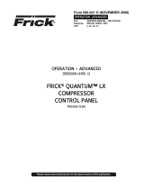
MENU STRUCTURE
The above graphic represents the menu structure, or tree,
of the Quantum™-LX Basic screens. Use this tree when
accessing the various screens. When this document is
viewed electronically, passing the mouse pointer over
each of the above names, and then clicking on it, will take
you directly to the page with that screen.
OPERATION OVERVIEW
Compressor Start-Up Procedure:
x The Operating Status screens provide quick access
to the most important information and controls of the
compressor unit and the subsystems.
x Starting status is shown for the Compressor on the
Operating Status screen.
x Press the button on the keypad (Start).
x All of the safeties are checked by the operating
software. If any shutdown condition is present, the
corresponding message will be shown, and the
compressor is prevented from starting.
x The oil lubrication is automatically checked. If a
problem has been detected, an appropriate message
is issued and the compressor is prevented from
starting. The problem will need to be resolved before
continuing.
x The Slide Valve position is checked automatically. If
the Slide Valve position is not correct, the compressor
is prevented from starting. The problem will need to
be resolved before continuing.
x If none of the above conditions has prevented the
compressor from starting, a time delay is started that
requires the starting conditions to remain satisfied for
a period of five seconds for all compressor model
types except [Other Compressor Manuf.]. The Other
compressor model type uses a 20 seconds delay.
After the time delay the compressor and the Recycle
Delay timer are started.
x If within 30 seconds, the Compressor Start Auxiliary
input has not been energized, or Motor Current is not
detected, then a message is issued and the
compressor is shut down. The problem will need to be
resolved before continuing.
x When the compressor begins running, the Oil
Pressure values can be in a state of change. For a
period of 10 seconds after the compressor status
switches to Running, the low Oil Pressure warning
and shutdown safeties are ignored.
x If all operating parameters are within acceptable
limits, the compressor will go into RUN mode. No
further operator intervention is normally needed.
Compressor Stopping Procedure:
Press the button on the keypad (Stop).
Once the compressor has been stopped, it cannot be
restarted again for 20 minutes, this is known as Recycle
Delay. Recycle delay time is the time that must elapse
prior to allowing the compressor to restart. It is intended to
prevent damage to the motor from successive restarts.
Home
Safeties…
Setpoints
Session
Help
About
Current
History

FRICK® QUANTUM™ LX COMPRESSOR CONTROL PANEL 90.020-O (MAY 07)
OPERATION - BASIC Page 5
OPERATING DISPLAY SCREENS
Operating Status
SCREEN NAME: Operating Status or Home.
ACCESSING:
DESCRIPTION: This is the default screen. When power is applied, this screen will appear. Also called the
Home screen. The most important information about the compressor and the applicable subsystems
operation is displayed here. This screen is shown when power is first turned on and when a key is pressed
after the screen saver has turned off the backlight. The Operating Status screen is continuously updated
and provides a variety of information with regard to the current condition and performance of the compressor
unit and subsystem.
The following information is shown on this screen:
DATE - The actual date will be displayed in this box.
The date must first be set correctly on the
Configuration screen. Once set, the date will be
automatically adjusted for at the end of each month,
much like the calendar feature of most modern
watches. The primary use of the date feature is to
provide a date stamp for Warnings and Shutdowns.
(See also TIME)
TIME - The actual time will be displayed in this box.
The time must first be set correctly on the
Configuration screen. The time will also need to be
adjusted for those locations which observe Daylight
Savings Time. The primary use of the time feature is
to provide a time stamp for Warnings and Shutdowns.
(See also Date)
SCREEN TITLE - This is the title for the screen that is
showing. Each screen will have a title. The
Quantum™ LX manuals will extensively refer to
screens by these names. When referred to in these
manuals, screen names will be shown in bold italic
print, such as Operating Status.
COMPRESSOR MODEL - This is actually a rotating
marquee. It will alternately display the model name of
the compressor (such as RWF) and will then rotate to
show Frick®. NOTE: The picture of the compressor
shown above is for a RWF II. Any other compressor
model may not appear the same, however, the values
discussed here do not change, regardless of the
compressor type.
COMPRESSOR RUN STATUS – This shows the
actual status of the compressor.
x Off
x Running
x Starting
x Stopping
x Stopping - High Capacity
x Stopping - Pumpdown
PROCESS SETPOINT VALUE - This is the control
setpoint maintained by the internal capacity control.
PROCESS ACTUAL VALUE - The actual reading of
the pressure or temperature that was chosen as the
compressor control setpoint.
Home

90.020-O (MAY 07) FRICK® QUANTUM™ LX COMPRESSOR CONTROL PANEL
Page 6 OPERATION - BASIC
ID - The value shown here is the number that has
been assigned to this particular unit on the
Communications Setup screen.
RUN HOURS – The value shown here is the total
number of hours that the compressor has been
actually running, since the last start.
WARNING/SHUTDOWNS STATUS AREA - The
Warning/Shutdowns Status is displayed near the
bottom left side of the screen. This area is blank with
no message if there are no warnings or shutdowns
present.
When a Warning or Shutdown occurs, a specific
message will be shown. The message will be followed
by either the word Warning or Shutdown. The
description of Warning and Shutdown are:
WARNING - This message flashes when a
warning is present. A warning is a condition that
requires operator acknowledgement and allows
the compressor to continue to run if it is running.
SHUTDOWN - This message flashes when a
shutdown is present. A shutdown is a condition
that requires an operator to acknowledge it and
causes the compressor to shut down. If the
compressor cannot be stopped, it is minimally run
in a protected state.
A Warning or Shutdown message indicates a
Warning or Shutdown point has been
reached, or exceeded.
When a Shutdown occurs, the display
backlight will flash on and off to alert an
operator of the shutdown. This visual alarm
will help get the attention of the operator in a
noisy engine room environment where
audible alarms may not be heard. Pressing
any key on the keypad will clear the flashing
backlight.
SENSOR READINGS - The following items are
shown:
Motor Amps - The actual amps.
Suction Pressure - Is measured at the
compressor inlet and the value is displayed along
with the unit of measure.
Suction Temperature - Is measured at the
compressor inlet and the value is displayed along
with the unit of measure.
Discharge Pressure - Is measured at the
compressor outlet and the value is displayed
along with the unit of measure.
Discharge Temperature - Is measured at the
compressor outlet and the value is displayed
along with the unit of measure.
Oil Pressure - Is measured prior to entering the
compressor and the value is displayed along with
the unit of measure.
Oil Temperature - Is measured prior to entering
the compressor and the value is displayed along
with the unit of measure.
Filter Differential - If applicable, pressure drop
across the oil filter. The main oil injection oil filter
pressure drop value (differential) is displayed
along with the unit of measure.
Separator Temperature - The Oil Separator
Temperature value is displayed along with the
unit of measure.

FRICK® QUANTUM™ LX COMPRESSOR CONTROL PANEL 90.020-O (MAY 07)
OPERATION - BASIC Page 7
Safeties - Current Safeties
SCREEN NAME: Current Safeties.
ACCESSING:
DESCRIPTION: The Current Safeties screen shows the Warnings and Shutdowns that have recently
occurred (up to 50). When a warning or shutdown is triggered, a blue descriptive message shows on this
screen. The date and time of the warning or shutdown occurrence is shown to the right of its description.
The most recent message will appear on the top line of the screen with the oldest appearing at the bottom.
When a Warning or Shutdown is logged to this screen, it will also be logged to the Safety History screen.
The following Current Safeties screen key is provided:
[Clear Safeties] - Selecting this key will clear all
warnings and/or shutdowns from this screen. It also
de-energizes the Warning output module and
energizes the Shutdown output module (digital
outputs 23 and 24) to silence any warning
annunciation device. This will also place a date/time
stamp for the corresponding entry on the Safety
History screen showing that the particular Warning or
Shutdown was cleared. Clearing the entry on the
Current Safeties screen, will not clear it from the
Safety History screen.
To resume normal operation it will be necessary to go
through the following steps:
1. Correct the condition(s) causing the warning.
2. Press the [ALARM SILENCE] key. (This action
may precede correcting the condition(s) causing
the warning). Or, go to step 3.
3. To clear or reset the Warnings/Shutdowns
screen and turn off any warning annunciation
device, from the screen, press the [Clear
Safeties] key. This will also clear any warning or
shutdown messages from the Operating Status
screen.
4. If the conditions causing the warning have not
been corrected or a new fault has occurred, a
new warning or shutdown message will appear.
The Safety History screen keeps a record of the
warnings and shutdowns. This information will
help troubleshoot persistent operational
problems.
Refer to the Warnings/Shutdowns Message section for a
list of all the possible conditions.
When a Shutdown occurs, the screen backlight will flash
on and off to alert an operator of the shutdown. This visual
indication will help get the attention of the operator in a
noisy engine room environment where audible alarms may
not be heard. Pressing any key on the keypad will clear
the flashing backlight.
Safeties… Current

90.020-O (MAY 07) FRICK® QUANTUM™ LX COMPRESSOR CONTROL PANEL
Page 8 OPERATION - BASIC
Safeties - History - Safety History
SCREEN NAME: Safety History.
ACCESSING:
DESCRIPTION: The Safety History screen shows the warnings and shutdowns that have recently occurred
(up to 50 maximum). When a warning or shutdown is triggered, a blue descriptive message shows on this
screen. The date and time of the warning or shutdown occurrence is shown to the right of its description,
followed by the date and time that the safety was cleared (if applicable, from the Current Safeties screen).
The most recent message will appear on the top line of the screen with the oldest appearing at the bottom.
Safeties… History

FRICK® QUANTUM™ LX COMPRESSOR CONTROL PANEL 90.020-O (MAY 07)
OPERATION - BASIC Page 9
Setpoints
SCREEN NAME: Capacity Control.
ACCESSING:
DESCRIPTION: All setpoints having to do with Compressor Control are found here.
This screen will list all Regulation modes which have been
setup by the supervisor. A setpoint box is provided next to
each available Regulation mode, along with the proper
units (pressure, temperature, etc.). The user may need to
set each box to the setpoint value that they wish to have
the compressor maintain for that particular mode.
Although the mode itself cannot be changed manually at
the Basic level, it can be changed automatically if the unit
has been set by the supervisor to run in Scheduling mode.
This feature is automatic in nature, and requires no
intervention by the operator. Scheduling will cause the
compressor to run in any four of the possible Regulation
modes, based upon a pre-programmed time schedule.
The following Regulation Modes could be shown
(depending on the setup):
x Regulation 1
x Regulation 2
x Regulation 3
x Regulation 4
Setpoints

90.020-O (MAY 07) FRICK® QUANTUM™ LX COMPRESSOR CONTROL PANEL
Page 10 OPERATION - BASIC
Session
SCREEN NAME: Session.
ACCESSING:
DESCRIPTION: This screen allows the user/supervisor to access the various available user levels. This is
also where the user can select the language, pressure units, temperature units and date format.
The following Setpoints may be changed:
User Level - Level 0 is referred to as the BASIC level,
and is used to access the very basics of compressor
operation. Level 0 requires no password.
Password - To access any level above level 0, a
password must be entered that matches the
password that has previously been assigned to each
user level by the supervisor.
The following pull-down menus have been provided:
Language - You may choose from the following list:
x English
x French
x Chinese
x Portuguese
Pressure Units - You may choose from the following
list:
x Kpaa
x Bar
x BarA
x PSIA
x PSIG/hg
Temperature Units - You may choose from the
following list:
x Celcius
x Fahrenheit
Date Format - You may choose from the following
list:
x US
x Europe
Session

FRICK® QUANTUM™ LX COMPRESSOR CONTROL PANEL 90.020-O (MAY 07)
OPERATION - BASIC Page 11
Help
SCREEN NAME: Help.
ACCESSING:
DESCRIPTION: This screen provides the user with specific information as to the function of all keypad keys,
as well as all screen keys, and changing Setpoints.
KEYPAD KEYS
Following is a list of the labeled keypad keys and the
actions that occur when they are pressed:
[STOP] - When the compressor is running in Manual
mode, this key immediately stops the
compressor by placing it into Stop Mode. The
compressor is stopped regardless of any other
conditions.
[START] - When in Manual Mode, this key places the
compressor unit into the Start Mode for running.
[INCREASE VALUE] - Increases Capacity.
[DECREASE VALUE] - Decreases Capacity.
[ALARM SILENCE] - Immediately silences a
sounding alarm and disables the alarm annunciation
device that may be connected to this panel.
[MANUAL] - Changes the compressor mode from its
current mode to its previous mode.
NUMERALS [0] - [9] - The numerical keys are used
to enter a value in a data field.
DECIMAL [.] - The decimal point is used when
entering a decimal value in a data field.
[+/-] - When changing a value in a data field, this key
will toggle the value between negative and positive.
[BACKSPACE] - Pressing this key will cause the
current location of the cursor to backup one position
per key depression. When changing a value in a data
field, this key will delete the selected character.
[UP ARROW] - Provides upward navigation within the
Main MENU window.
[TAB] - When in the mode of changing setpoints,
pressing this key will cause the cursor to jump to the
next data entry field.
[LEFT ARROW] - When in the mode of changing
setpoints, this arrow is used to go to the previous
character within a data entry field. When the MAIN
MENU is shown, pressing this key will cancel the
window.
[DOWN ARROW] - Provides downward navigation
within the MAIN MENU window.
[RIGHT ARROW] - When in the mode of changing a
data entry field, this arrow is used to go to the next
character.
[ENTER] - When changing data in a data entry field,
this key will accept the change. This key is also used
to select items on Menu Windows.
[SUBMIT] - After changing a setpoint value, Use this
key to enter (submit) the change.
[MENU] - Shows the MAIN MENU window. This
window shows the main selections for accessing
information, setup of options, and setpoint entry.
Help

90.020-O (MAY 07) FRICK® QUANTUM™ LX COMPRESSOR CONTROL PANEL
Page 12 OPERATION - BASIC
SCREEN KEYS
TO CHANGE THE ADJUSTABLE SETPOINTS
The adjustable setpoints define the operation and limits of
the compressor unit and subsystems operation. Adjustable
Setpoints are stored in EEPROM (non-volatile memory)
and are easily changed in the field.
NOTE: Adjustable Setpoints are not lost after power is
interrupted. However, we suggest that a list of Adjustable
Setpoints be recorded and stored safely to facilitate
reentry, in case there is a need to return to the original
settings.
The [TAB] key is used to maneuver around the screen.
Use the arrow keys to move the cursor to the data entry
field to be modified.
Having selected the setpoint to be changed, the numerical
keys and the decimal key may be used to enter the new
setpoint. Typing a new value will completely erase the old
value.
To remove a typing mistake, the left and right arrow key
can be used to position the cursor on the mistake and then
use the [BACKSPACE] key to erase it.
Press the [ENTER] key to input the new data in the data
entry field.
If the value is out of bounds, an error message box shows
and displays the proper value range. Press the [OK] key
to acknowledge that you saw the error message. Re-enter
the correct value.
Pressing the [Enter] key inputs the new setpoint and
selects the next data entry field.
When finished making any changes to the data on an
adjustable setpoint, press the [SUBMIT] key to accept all
changes or select another screen to cancel all of the data
changes.
Note: When the display units are selected to display in
PSIG, an entry of a pressure value above 29.7 is assumed
to be PSIG, an entry less than or equal to 29.7 will cause
a message box to appear after pressing the [ENTER] key.
This message prompts the operator to select the unit of
measure. The operator must select either the [HG] or the
[PSIG] key.
To resume normal operation it will be necessary to go
through the following steps:
Correct the conditions causing the alarm.
Press the [ALARM SILENCE] key. (This action may
precede correcting the conditions causing the alarm).
To clear or reset the 'Warnings/Shutdowns' screen, from
the 'Current Safeties' screen press the [Clear Safeties]
key. This will also clear the 'WARNING' or 'SHUTDOWN'
message from the Operating Status screen.
If the conditions causing the fault have not been corrected
or a new fault has occurred, a new 'WARNING' or
'SHUTDOWN' message will appear. The
Warning/Shutdowns history screen keeps a record of the
warnings and shutdowns. This information will help
troubleshoot persistent operational problems.

FRICK® QUANTUM™ LX COMPRESSOR CONTROL PANEL 90.020-O (MAY 07)
OPERATION - BASIC Page 13
About
SCREEN NAME: About.
ACCESSING:
DESCRIPTION: The About screen shows all microprocessor-based circuit boards that have been detected
by the Quantum™ LX, as well other related software information.
The following information is shown here:
Linux Kernel - The Quantum™ LX controller runs on
a Linux programming architecture (rather than
Microsoft Windows). This is the software version
number for the main Linux Kernel (or program).
York Quantum Software - This is the version of the
software program that does the actual control of the
compressor. It runs in the Linux environment.
Sales Order - A six digit numerical value that has
been assigned to a specific compressor package by
Frick Company. It is very important to have this
number available when calling the factory for
assistance or parts ordering.
Item - This is actually an extension of the Sales Order
number. It would potentially be used for a multiple
compressor site, where the same Sales Order
number was assigned for all compressors. The Item
Number would be different for each compressor.
Analog Boards - Shows all analog boards that were
detected through communications at the last power
up. If a board is detected, the software version of the
program running on that board (with date of the
software) will be shown.
Digital Boards - Shows all digital boards that were
detected through communications at the last power
up. If a board is detected, the software version of the
program running on that board (with date of the
software) will be shown.
IO Boards - Shows all other I/O boards that were
detected through communications at the last power
up. If a board is detected, the software version of the
program running on that board (with date of the
software) will be shown.
Drive Controller - Shows motor or engine drive
controllers that were detected through
communications at the last power up. If a board is
detected, the software version of the program running
on that board (with date of the software) will be
shown.
About

90.020-O (MAY 07) FRICK® QUANTUM™ LX COMPRESSOR CONTROL PANEL
Page 14 OPERATION - BASIC
Warnings/Shutdowns Messages
When a Shutdown occurs, the display backlight will flash
on and off to alert an operator of the shutdown. This visual
warning will help get the attention of the operator in a
noisy engine room environment where audible alarms may
not be heard. Pressing any key on the keypad will clear
the flashing backlight.
NOTE: refer to S100-200/210 IOM for further Vyper
message details.
Following is the alphabetical listing of all the possible
conditions:
Analog Board 1 Communications Shutdown - It has
been detected that the program is no longer able to
communicate to Analog Board 1.
Analog Board 2 Communications Shutdown - It has
been detected that the program is no longer able to
communicate to Analog Board 2.
Auxiliary Input 1-20 Shutdown - The Auxiliary #1-20
input module has been setup to indicate a shutdown when
it is de-energized and it became de-energized.
Auxiliary Input 1-20 Warning - The Auxiliary #1-20 input
module has been setup to indicate a warning when it is
de-energized and it became de-energized.
Balance Piston 1 Shutdown - Balance piston control has
been enabled. This shutdown will occur if the difference
between Discharge Pressure and Suction Pressure is less
than 60 lb. and the Balance Piston output module (digital
output module 12) is de-energized, then the Balance
Piston pressure must be 1.1 times Suction Pressure plus
or minus 15 lb.
Balance Piston 2 Shutdown - Balance piston control has
been enabled. This shutdown will occur if the difference
Discharge Pressure and Suction Pressure is greater than
or equal to 60 lb. and the Balance Piston output module
(digital output module 12) is de-energized, then the
Balance Piston pressure must be 50 lb. below Discharge
Pressure plus or minus 15 lb.
Balance Piston 3 Shutdown - Balance piston control has
been enabled. This shutdown will occur if the Balance
Piston output module (digital output module 12) is
energized, then Balance Piston pressure must be within
20lb. of Oil Pressure.
Compressor Auxiliary Shutdown - This shutdown
message is issued if while the compressor is running, the
Compressor Auxiliary input module, which receives
feedback from the motor starter, becomes de-energized.
Compressor Capacity Unload Warning - While stopping
the compressor or if the compressor is off, this indicates
that the Slide Valve position has not unloaded below the
Highest Slide Valve Position to allow starting the
compressor setpoint.
DBS Communication Failure Warning – It has been
detected that the program is no longer able to
communicate to a RAM DBS Motor Starter.
DBS - Communication Failure Shutdown - It has been
detected that the program is no longer able to
communicate to a RAM DBS Motor Starter.
DBS - Current Unbalance – Either the current between
two phases has exceeded the setpoint value longer than
the time delay setpoint, or there is a voltage unbalance
between phases, or the SCR operation is abnormal.
DBS - Heatsink Over-temperature – Either the
temperature of the heat sink has exceeded the maximum
safe operating temperature of 85 deg. C. or heat sink
cable connection P2 is loose.
DBS – Jam – The current exceeded the Jam Trip level set
point longer than the time delay set point while in the RUN
state.
DBS - Phase Loss – This will occur if there is a loss of at
least one phase of supply voltage or the loss of at least
one phase of current feedback.
DBS - Phase Reversal – Either there is an incorrect
phase order at the DBS chassis input terminals, or the
control power was applied before the three phase power.
DBS - RTD Overtemperature –The RTD temperature
sensor is out of range.
DBS - RTD Temperature – The RTD temperature sensor
is out of range.
DBS - Short Circuit – The current exceeded 800% of FLA
set point while the motor was starting.
DBS - Shorted SCR – This failure may occur if there is a
defective SCR or a defective bypass contactor. It may also
occur if the motor is disconnected. Also, inspect the main
contacts of the bypass contactor.
DBS - Thermal Overload – Either the calculated thermal
capacity of the motor exceeded 100% of limit, or the motor
is "short-cycling".
Digital Board 1 Communications Shutdown - It has
been detected that the program is no longer able to
communicate to Digital Board 1.
Digital Board 1 Reset - If a reset of Digital Board 1
occurs, a shutdown will result to prevent the motor from
restarting.
Digital Board 2 Communications Shutdown - It has
been detected that the program is no longer able to
communicate to Digital Board 2.
Digital Board 2 Reset - If a reset of Digital Board 2
occurs, a shutdown will result to prevent the motor from
restarting.
Discharge Temperature Saturation Shutdown - This
Shutdown applies if Superheat has been enabled. When

FRICK® QUANTUM™ LX COMPRESSOR CONTROL PANEL 90.020-O (MAY 07)
OPERATION"!3)# Page 15
running, a shutdown will occur if TDsat plus setpoint
temperature is greater than the Discharge Temperature for
the setpoint time.
Discharge Temperature Saturation Warning - This
warning applies if Superheat has been enabled. When
running, a warning will occur if TDsat plus setpoint
temperature is greater than the Discharge Temperature for
the setpoint time.
False Running Failure -- Compressor Confirmed
Running Input - This shutdown message is issued if while
the compressor is off the compressor auxiliary is
energized. While this condition is present, the Oil Pump (if
available) is on, and Liquid Injection (if available) is
allowed on and the Slide Valve is unloaded to 0% to
safeguard the compressor.
False Running Failure -- Motor Amps - This shutdown
message is issued if while the compressor is off, the Motor
Current reading is above the Low Motor Amps Shutdown
setpoint. While this condition is present, the Oil Pump (if
available) is on, and Liquid Injection (if available) is
allowed on and the Slide Valve is unloaded to 0% to
safeguard the compressor.
High Auxiliary Analog 1-20 Shutdown - The Auxiliary
Analog #1-20 value was greater than or equal to the high
Auxiliary Analog #1-20 shutdown setpoint for its time
delay.
High Auxiliary Analog 1-20 Warning - The Auxiliary
Analog #1-20 value was greater than or equal to the high
Auxiliary Analog #1-20 warning setpoint for its time delay.
High Compressor Vibration Shutdown - Suction - If the
Suction End Compressor Vibration sensor registers a
reading that is higher than the value that has been set for
the Suction End High Shutdown, for the period of time as
set for the Suction End High Shutdown Delay, a Shutdown
will be generated.
High Compressor Vibration Warning - Suction - If the
Suction End Compressor Vibration sensor registers a
reading that is higher than the value that has been set for
the Suction End High Warning, for the period of time as
set for the Suction End High Warning Delay, a Warning
will be generated.
High Compressor Vibration Shutdown - Discharge - If
the Discharge End Compressor Vibration sensor registers
a reading that is higher than the value that has been set
for the Discharge End High Shutdown, for the period of
time as set for the Discharge End High Shutdown Delay, a
Shutdown will be generated.
High Compressor Vibration Warning - Discharge - If
the Discharge End Compressor Vibration sensor registers
a reading that is higher than the value that has been set
for the Discharge End High Warning, for the period of time
as set for the Discharge End High Warning Delay, a
warning will be generated.
High Discharge Pressure Shutdown – The Discharge
Pressure was greater than or equal to the active High
Discharge Pressure Shutdown setpoint for its time delay.
High Discharge Pressure Warning – The Discharge
Pressure was greater than or equal to the active High
Discharge Pressure Warning setpoint for its time delay.
High Discharge Pressure Shutdown -- Dual Discharge
Mode 1 - The Discharge Pressure was greater than or
equal to the active High Discharge Pressure Shutdown
setpoint for its time delay.
High Discharge Pressure Warning -- Dual Discharge
Mode 1 - The Discharge Pressure was greater than or
equal to the active High Discharge Pressure Warning
setpoint for its time delay.
High Discharge Pressure Shutdown -- Dual Discharge
Mode 2 - The Discharge Pressure was greater than or
equal to the active High Discharge Pressure Shutdown
setpoint for its time delay.
High Discharge Pressure Warning -- Dual Discharge
Mode 2 - The Discharge Pressure was greater than or
equal to the active High Discharge Pressure Warning
setpoint for its time delay.
High Discharge Pressure Sensor Fault - This shutdown
message is issued if the Discharge Pressure reading was
to the upper or maximum range (out of range) for its
sensor.
High Discharge Temperature Shutdown - The
Discharge Temperature was greater than or equal to the
High Discharge Temperature Shutdown setpoint for its
time delay.
High Discharge Temperature Warning - The Discharge
Temperature was greater than or equal to the High
Discharge Temperature Warning setpoint for its time
delay.
High Economizer Shutdown - The Auxiliary Analog #10
value was greater than or equal to the high Auxiliary
Analog #10 shutdown setpoint for its time delay.
High Economizer Warning - The Auxiliary Analog #10
value was greater than or equal to the high Auxiliary
Analog #10 warning setpoint for its time delay.
High Entering Process Temperature Shutdown - The
Entering Process Temperature was greater than or equal
to the High Entering Process Temperature Shutdown
setpoint for its time delay.
High Entering Process Temperature Warning - The
Entering Process Temperature was greater than or equal
to the High Entering Process Temperature Warning
setpoint for its time delay.
High Limit Discharge Pressure Shutdown - The
Discharge Pressure was greater than or equal to the
active High Discharge Pressure Shutdown setpoint for its
time delay.
High Limit Discharge Temperature Shutdown - The
Discharge Temperature was greater than or equal to the
active High Discharge Temperature Shutdown setpoint for
its time delay.

90.020-O (MAY 07) FRICK® QUANTUM™ LX COMPRESSOR CONTROL PANEL
Page 16 OPERATION - BASIC
High Liquid Level Shutdown - The corresponding input
module was de-energized.
High Manifold Pressure Shutdown - This shutdown
applies if Engine Drive was enabled. When the Manifold
Pressure exceeds this setpoint, an alarm will occur.
High Manifold Pressure Warning - This warning applies
if Engine Drive was enabled. When the Manifold Pressure
exceeds this setpoint, a warning will occur.
High Motor Current Shutdown - The motor amps was
greater than or equal to the High Motor Amps Shutdown
setpoint for its time delay.
High Motor Current Warning - The Motor Amps was
greater than or equal to the High Motor Amps Warning
setpoint for its time delay.
High Motor Stator #1 Temperature Warning – If Motor
Stator #1 temperature sensor registers a reading that is
higher than the value that has been set for the Motor
Stator #1 Temp. Warning, for the period of time as set for
the Motor Stator #1 Temp. Warning Delay, a warning will
be generated.
High Motor Stator #1 Temperature Shutdown – If Motor
Stator #1 temperature sensor registers a reading that is
higher than the value that has been set for the Motor
Stator #1 Temp. Shutdown, for the period of time as set
for the Motor Stator #1 Temp. Shutdown Delay, a
Shutdown will be generated.
High Motor Stator #2 Temperature Warning – If Motor
Stator #2 temperature sensor registers a reading that is
higher than the value that has been set for the Motor
Stator #2 Temp. Warning, for the period of time as set for
the Motor Stator #2 Temp. Warning Delay, a warning will
be generated.
High Motor Stator #2 Temperature Shutdown – If Motor
Stator #2 temperature sensor registers a reading that is
higher than the value that has been set for the Motor
Stator #2 Temp. Shutdown, for the period of time as set
for the Motor Stator #2 Temp. Shutdown Delay, a
Shutdown will be generated.
High Motor Stator #3 Temperature Warning – If Motor
Stator #3 temperature sensor registers a reading that is
higher than the value that has been set for the Motor
Stator #3 Temp. Warning, for the period of time as set for
the Motor Stator #3 Temp. Warning Delay, a warning will
be generated.
High Motor Stator #3 Temperature Shutdown – If Motor
Stator #3 temperature sensor registers a reading that is
higher than the value that has been set for the Motor
Stator #3 Temp. Shutdown, for the period of time as set
for the Motor Stator #3 Temp. Shutdown Delay, a
Shutdown will be generated.
High Motor Temperature Warning - Shaft Side – The
motor has temperature sensors that monitor the Shaft
Side bearing. If the temperature of this bearing exceeds
the Shaft Side High Warning setpoint, for a period of time
exceeding the Shaft Side High Warning Delay setpoint,
this Warning will occur. The default values for these
setpoints are 203° F and a delay of 5 seconds.
High Motor Temperature Warning - Opposite Shaft Side –
The motor has temperature sensors that monitor the
Opposite Shaft Side bearing. If the temperature of this
bearing exceeds the Opposite Shaft Side High Warning
setpoint, for a period of time exceeding the Opposite Shaft
Side High Warning Delay setpoint, this Warning will occur.
The default values for these setpoints are 203° F and a
delay of 5 seconds.
High Motor Temperature Shutdown - Shaft Side – The
motor has temperature sensors that monitor the Shaft
Side bearing. If the temperature of this bearing exceeds
the Shaft Side High Shutdown setpoint, for a period of
time exceeding the Shaft Side High Shutdown Delay
setpoint, this Shutdown will occur. The default values for
these setpoints are 221° F and a delay of 5 seconds.
High Motor Temperature Shutdown - Opposite Shaft Side –
The motor has temperature sensors that monitor the
Opposite Shaft Side bearing. If the temperature of this
bearing exceeds the Opposite Shaft Side High Shutdown
setpoint, for a period of time exceeding the Opposite Shaft
Side High Shutdown Delay setpoint, this Shutdown will
occur. The default values for these setpoints are 221° F
and a delay of 5 seconds.
High Motor Vibration Shutdown - Opposite Shaft Side
- If the Opposite Shaft Side Drive Vibration sensor
registers a reading that is higher than the value that has
been set for the Opposite Shaft High Shutdown, for the
period of time as set for the Opposite Shaft High
Shutdown Delay, a Shutdown will be generated.
High Motor Vibration Warning - Opposite Shaft Side -
If the Opposite Shaft Side Drive Vibration sensor registers
a reading that is higher than the value that has been set
for the Opposite Shaft High Warning, for the period of time
as set for the Opposite Shaft High Warning Delay, a
warning will be generated.
High Motor Vibration Shutdown - Shaft Side - If the
Shaft Side Drive Vibration sensor registers a reading that
is higher than the value that has been set for the Shaft
Side High Shutdown, for the period of time as set for the
Shaft Side High Shutdown Delay, a Shutdown will be
generated.
High Motor Vibration Warning - Shaft Side - If the Shaft
Side Drive Vibration sensor registers a reading that is
higher than the value that has been set for the Shaft Side
High Warning, for the period of time as set for the Shaft
Side High Warning Delay, a warning will be generated.
High Oil Filter Pressure Warning - The Oil Filter
Pressure was greater than or equal to the High Filter
Pressure Warning setpoint for its time delay.
High Oil Filter Pressure Shutdown - The Oil Filter
Pressure was greater than or equal to the High Filter
Pressure Shutdown setpoint for its time delay.

FRICK® QUANTUM™ LX COMPRESSOR CONTROL PANEL 90.020-O (MAY 07)
OPERATION"!3)# Page 17
High Oil Pressure Sensor Fault - This shutdown
message is issued if the Oil Pressure reading was to the
upper or maximum range (out of range) for its sensor.
High Oil Pressure Shutdown – The Oil Pressure was
greater than or equal to the High Oil Pressure Shutdown
setpoint for its time delay.
High Oil Temperature Shutdown - The Oil Temperature
was greater than or equal to the High Oil Temperature
Shutdown setpoint for its time delay.
High Oil Temperature Warning - The Oil Temperature
was greater than or equal to the High Oil Temperature
Warning setpoint for its time delay.
High RPM Shutdown - This shutdown applies if Engine or
Turbine Drive was enabled. If the RPM's of the motor
exceeds this setpoint, a shutdown will occur.
High RPM Warning - This warning applies if Engine or
Turbine Drive was enabled. If the RPM's of the motor
exceeds this setpoint, a warning will occur.
High Suction Pressure Shutdown - The Suction
Pressure was greater than or equal to the active High
Suction Pressure Shutdown setpoint for its time delay.
High Suction Pressure Warning - The Suction Pressure
was greater than or equal to the active High Suction
Pressure Warning setpoint for its time delay.
Insufficient Main Oil Pressure Shutdown - The Slide
Valve is greater than 50% and the Oil Pressure (PSIA) is
less than or equal to the Suction Pressure (PSIA)
multiplied by 1.5 and then added to 15.0.
Kobe High Oil Pressure Shutdown – If the compressor
type is set to Other Manufacturer (Kobe), the oil pump
type is set to Demand and if Oil Pressure rises above 325
PSIA for more than 5 seconds this shutdown will occur.
This shutdown is only active when the compressor is
running and is also not checked for the first 90 seconds
after the compressor starts.
Kobe Low Oil Differential 1 Shutdown – If the
compressor type is set to Other Manufacturer (Kobe), the
oil pump type is set to Demand and if the differential
between Oil Pressure and Suction Pressure is less than
50 PSI for 5 seconds this shutdown will occur. This
shutdown is only active when the compressor is running
and is also not checked for the first 90 seconds after the
compressor starts.
Kobe Low Oil Differential 2 Shutdown – If the
compressor type is set to Other Manufacturer (Kobe), the
oil pump type is set to Demand and the differential
between Oil Pressure and Suction Pressure is less than
Suction Pressure times 0.8 for 5 seconds this shutdown
will occur. This shutdown is only active when the
compressor is running and is also not checked for the first
90 seconds after the compressor starts.
Liquid Slugging Shutdown - This shutdown is triggered
off of a sudden decrease in Discharge Temperature that is
greater than the Liquid Slugging Shutdown setpoint for a
five (5) second period. That is, if the Discharge
Temperature is 130 degrees F, and the Liquid Slug
Shutdown setpoint is 20 degrees F, then a sudden drop in
Discharge Temperature from 130 to 110 degrees F within
a five second period will generate a shutdown condition.
Liquid Slugging Warning - This warning is triggered off
of a sudden decrease in Discharge Temperature that is
greater than the Liquid Slug Warning setpoint for a five (5)
second period. That is, if the Discharge Temperature is
130 degrees F, and the Liquid Slugging Warning setpoint
is 10 degrees F, then a sudden drop in Discharge
Temperature from 130 to 120 degrees F within a five
second period will generate a warning condition.
Low Auxiliary Analog 1-20 Shutdown - The Auxiliary
Analog #1-20 value was less than or equal to the low
Auxiliary Analog #1-20 shutdown setpoint for its time
delay.
Low Auxiliary Analog 1-20 Warning - The Auxiliary
Analog #1-20 value was less than or equal to the low
Auxiliary Analog #1-20 warning setpoint for its time delay.
Low Discharge Pressure Sensor Fault - This shutdown
message is issued if the Discharge Pressure reading was
to the lower or minimum range (out of range) for its
sensor.
Low Discharge Temperature Sensor Fault - This
shutdown message is issued if the Discharge
Temperature reading was to the lower or minimum range
(out of range) out of range for its sensor.
Low Economizer Shutdown - The Auxiliary Analog #10
value was less than or equal to the low Auxiliary Analog
#10 shutdown setpoint for its time delay.
Low Economizer Warning - The Auxiliary Analog #10
value was less than or equal to the low Auxiliary Analog
#10 warning setpoint for its time delay.
Low Entering Process Temperature Shutdown - The
Entering Process Temperature was less than or equal to
the Low Entering Process Temperature Shutdown setpoint
for its time delay.
Low Entering Process Temperature Warning - The
Entering Process Temperature was less than or equal to
the Low Entering Process Temperature Warning setpoint
for its time delay.
Low Main Oil Injection Pressure Shutdown - This
shutdown can occur if Oil Injection was enabled. The Oil
Injection Pressure (channel 15, Analog Board 2) must
greater than or equal to the Suction Pressure times 1.5,
plus the setpoint to be in the safe condition, otherwise this
shutdown will occur.
Low Motor Current Shutdown - This shutdown message
is issued if, while the compressor was running, the Motor
Amps reading was less than or equal to the Low Motor
Amps Shutdown setpoint.
Low Oil Pressure Sensor Fault - This shutdown
message is issued if the Oil Pressure reading was to the
lower minimum range (out of range) for its sensor.

90.020-O (MAY 07) FRICK® QUANTUM™ LX COMPRESSOR CONTROL PANEL
Page 18 OPERATION - BASIC
Low Oil Pressure Shutdown - The compressor was
running. Either the Oil Pressure of a running pump was
less than or equal to the Low Oil Pressure Shutdown
setpoint, or the Oil Pressure of a not running pump was
less than or equal to the Low Oil Pressure Shutdown
setpoint for its time delay.
Low Oil Pressure Warning - The compressor was
running. Either the Oil Pressure of a running pump was
less than or equal to the Low Oil Pressure Warning
setpoint, or the Oil Pressure of a not running pump was
less than or equal to the Low Oil Pressure Warning
setpoint for its time delay.
Low Oil Temperature Sensor Fault - This shutdown
message is issued if the Oil Temperature reading was to
the lower or minimum range (out of range) for its sensor.
Low Oil Temperature Shutdown - The Oil Temperature
was less than or equal to the Low Oil Temperature
Shutdown setpoint for its time delay.
Low Oil Temperature Warning - The Oil Temperature
was less than or equal to the Low Oil Temperature
Warning setpoint for its time delay.
Low RPM Shutdown - This shutdown applies if Engine or
Turbine Drive was enabled. If the RPM's of the motor
drops below this setpoint, a shutdown will occur.
Low RPM Warning - This warning applies if Engine or
Turbine Drive was enabled. If the RPM's of the motor
drops below this setpoint, a warning will occur.
Low Separator Temperature Sensor Fault - This
shutdown message is issued if the Separator Temperature
reading was to the lower or minimum range (out of range)
for its sensor.
Low Separator Temperature Shutdown - The Oil
Separator Temperature was less than or equal to the Low
Oil Separator Temperature Shutdown setpoint for its time
delay.
Low Separator Temperature Warning - The Oil
Separator Temperature was less than or equal to the Low
Oil Separator Temperature Warning setpoint for its time
delay.
Low Suction Pressure Sensor Fault - This shutdown
message is issued if the Suction Pressure reading was to
the lower or minimum range (out of range) for its sensor.
Low Suction Shutdown -- Regulation Mode 1 - When
running in Regulation Mode 1, if the Suction Pressure was
less than or equal to the active Regulation Mode 1 Low
Suction Shutdown setpoint for its time delay.
Low Suction Warning -- Regulation Mode 1 - When
running in Regulation Mode 1, if the Suction Pressure was
less than or equal to the active Regulation Mode 1 Low
Suction Warning setpoint for its time delay.
Low Suction Shutdown -- Regulation Mode 2 - When
running in Regulation Mode 2, if the Suction Pressure was
less than or equal to the active Regulation Mode 2 Low
Suction Shutdown setpoint for its time delay.
Low Suction Warning – Regulation Mode 2 - When
running in Regulation Mode 2, if the Suction Pressure was
less than or equal to the active Regulation Mode 2 Low
Suction Warning setpoint for its time delay.
Low Suction Shutdown -- Regulation Mode 3 - When
running in Regulation Mode 3, if the Suction Pressure was
less than or equal to the active Regulation Mode 3 Low
Suction Shutdown setpoint for its time delay.
Low Suction Warning -- Regulation Mode 3 - When
running in Regulation Mode 3, if the Suction Pressure was
less than or equal to the active Regulation Mode 3 Low
Suction Warning setpoint for its time delay.
Low Suction Shutdown – Regulation Mode 4 - When
running in Regulation Mode 4, if the Suction Pressure was
less than or equal to the active Regulation Mode 4 Low
Suction Shutdown setpoint for its time delay.
Low Suction Warning – Regulation Mode 4 - When
running in Regulation Mode 4, if the Suction Pressure was
less than or equal to the active Regulation Mode 4 Low
Suction Warning setpoint for its time delay.
Missing Oil Pressure Shutdown A - The Oil Pressure
(PSIA) is less than the Suction Pressure (PSIA) multiplied
by 1.1 and then added to 15.0, then delayed by 2 min.
Missing Oil Pressure Shutdown B - The Oil Pressure
(PSIA) is less than the Suction Pressure (PSIA) added to
15.0, then delayed by 25 sec.
Missing Oil Pressure Warning - The Oil Pressure (PSIA)
is less than the Suction Pressure (PSIA) multiplied by 1.1
and then added to 15.0, then delayed by 25 sec.
Oil Level Shutdown - The corresponding input module for
low Oil Level was de-energized for five (5) minutes.
Oil Log Shutdown - Oil log was enabled and the
Compressor has not started and the Oil Pump has already
run for the fail delay time.
Oil Pump Auxiliary Failure - While starting the Oil Pump,
the Oil Pump Auxiliary input module did not energize
within five (5) seconds, or, while the Oil Pump was
running, the Oil Pump Auxiliary input module de-
energized.
Oil Pump 1 Auxiliary Warning - While starting Oil Pump
#1, the Oil Pump #1 Auxiliary input module did not
energize within five (5) seconds, or, while this Oil Pump
was running, the Oil Pump #1 Auxiliary input module de-
energized. This indicates Dual Pump Control and Pump
#1 is the lead pump.
Oil Pump 1 Auxiliary Shutdown - While starting Oil
Pump #1, the Oil Pump #1 Auxiliary input module did not
energize within five (5) seconds, or, while this Oil Pump
was running, the Oil Pump #1 Auxiliary input module de-
energized. This indicates Dual Pump Control and Pump
#1 is the last pump to start.
Oil Pump 2 Auxiliary Warning - While starting Oil Pump
#2, the Oil Pump #2 Auxiliary input module did not
energize within five (5) seconds, or, while this Oil Pump
was running the Oil Pump #2 Auxiliary input module de-

FRICK® QUANTUM™ LX COMPRESSOR CONTROL PANEL 90.020-O (MAY 07)
OPERATION "!3)# Page 19
energized. This indicates Dual Pump Control and Pump
#2 is the lead pump.
Oil Pump 2 Auxiliary Shutdown - While starting Oil
Pump #2, the Oil Pump auxiliary input module did not
energize within five (5) seconds, or, while the Oil Pump
was running, the Oil Pump auxiliary input module de-
energized. This indicates Dual Pump Control and Pump
#2 is the last pump to start.
Process Stopped - Check Event Log for Details – One
of the control program subroutine processes has stopped
functioning and a message has been entered into the
event log. This is a Warning message.
Regulation Mode 1 Shutdown – When the selected
regulation control process for Regulation Mode 1 has
exceeded it’s setpoint for the delay period, a Shutdown
occurs.
Regulation Mode 1 Warning – When the selected
regulation control process for Regulation Mode 1 has
exceeded it’s setpoint for the delay period, a Warning
occurs.
Regulation Mode 2 Shutdown – When the selected
regulation control process for Regulation Mode 2 has
exceeded it’s setpoint for the delay period, a Shutdown
occurs.
Regulation Mode 2 Warning – When the selected
regulation control process for Regulation Mode 2 has
exceeded it’s setpoint for the delay period, a Warning
occurs.
Regulation Mode 3 Shutdown – When the selected
regulation control process for Regulation Mode 3 has
exceeded it’s setpoint for the delay period, a Shutdown
occurs.
Regulation Mode 3 Warning – When the selected
regulation control process for Regulation Mode 3 has
exceeded it’s setpoint for the delay period, a Warning
occurs.
Regulation Mode 4 Shutdown – When the selected
regulation control process for Regulation Mode 4 has
exceeded it’s setpoint for the delay period, a Shutdown
occurs.
Regulation Mode 4 Warning - When the selected
regulation control process for Regulation Mode 4 has
exceeded it’s setpoint for the delay period, a Warning
occurs.
Sequencing Slide Valve Failure Shutdown – When in
sequencing mode, if the controlling compressor fails to
properly load the Slide Valve, a shutdown occurs, and
control moves to the next compressor.
Start Failure Shutdown For Engine And Turbine - This
message may be issued if Engine or Turbine was enabled,
and the start delay period to get to a running condition has
expired.
Starting Failure - Low Motor Amps - This shutdown
message is displayed if after 30 seconds from sending the
compressor start signal, the Motor Amps reading is not
greater than the Low Motor Amps Shutdown setpoint.
Starting Failure - No Compressor Auxiliary - This
shutdown message is displayed if after 450 seconds from
sending the compressor start command, the compressor
auxiliary input module is still not energized.
Starting Low Oil Pressure Shutdown – This safety is
active if the compressor type is set to Other Manufacturer,
Other Manufacturer (Kobe) or Other Manufacturer
(Mycom) and the oil pump type is set to Full Time. When
the compressor is starting, if Oil Pressure does not rise
above Discharge Pressure plus the Low Oil Pressure
Shutdown setpoint plus 10 PSI within 30 seconds this
shutdown will occur. The default value for the Low Oil
Pressure Shutdown setpoint is 20 PSI.
Starting Superheat Shutdown - This message may be
issued if Superheat was enabled. A shutdown will occur if
TDsat plus temperature setpoint is greater than the
Separator temperature.
Stopping Failure - Compressor Auxiliary - This
shutdown message is issued if while stopping the
compressor, after 8 seconds from the compressor stop
command, the compressor auxiliary is energized. While
this condition is present, the Oil Pump (if available) is on
and Liquid Injection (if available) is allowed on and the
Slide Valve is unloaded to 0% to safeguard the
compressor.
Stopping Failure - Motor Amps - This shutdown
message is issued if while stopping the compressor, after
12 seconds from the compressor stop command, the
Motor Current reading is above the Low Motor Amps
Shutdown setpoint. While this condition is present, the Oil
Pump (if available) is on, and Liquid Injection (if available)
is allowed on and the Slide Valve is unloaded to 0% to
safeguard the compressor.
Vyper - Interface Board Power Supply - This fault is set
on every power-up. It is immediately cleared, and logged
in the fault history to record the occurrence of the power
loss.
Vyper Communications Failure Warning - If Vyper
option is enabled and the Comms communication has
failed, this warning is shown.
Vyper - Interface Board to Panel Communications
Loss - This fault occurs when the Frick Interface Board
loses communications from the Quantum™ LX Control
Panel, meaning it has not received any data for a period of
fifteen seconds. It is only applicable in automatic mode.
Vyper - Interface Board Motor Current > 15% - This
fault occurs whenever the Vyper™ is running and a motor
current of less than 10 % FLA is detected for at least
twenty-five continuous seconds. This fault is only checked
when the Run Acknowledge output is engaged. Therefore,
it is NOT checked during STANDBY, which prevents this
fault from occurring during STANDBY.
Vyper - Interface Board Run Signal - This fault occurs if
the Run Signal from the Quantum Control Panel is high,
but the speed command being sent over the RS-485

90.020-O (MAY 07) FRICK® QUANTUM™ LX COMPRESSOR CONTROL PANEL
Page 20 OPERATION - BASIC
communications link is zero. It may also occur if the Run
Signal is low, but the speed command is not zero. Both
conditions must be present for five seconds before the
fault is set, and are only applicable in automatic mode.
Vyper – Initialization - At power-up, all the boards go
through a process called initialization. At this time,
memory locations are cleared, jumper positions are
checked, and serial communications links are established.
Vyper - Stop Contacts - This fault occurs if the No Fault
signal from the Vyper™ is low. It indicates a fault is
present at the Vyper™ or the Harmonic Filter, but the
communications data contains no Vyper™ fault data for
twenty seconds. The Frick Interface Board will send
Initialize data requests while this fault is active.
Vyper - Harmonic Filter Logic Board Or
Communications – This fault occurs if the No Fault signal
from the Vyper™ is low, indicating a fault is present at the
Vyper™ or the Harmonic Filter, but the communications
data contains no Harmonic Filter fault data for twenty
seconds. The Frick Interface Board will send Initialize data
requests while this fault is active.
Vyper - Harmonic Filter High Total Demand Distortion
– This shutdown indicates that the filter is not operating
correctly or the input current to the Vyper™ / filter system
is not sinusoidal. This fault occurs when any of the three
phases of Total Demand Distortion is greater than 25.0 %,
for forty-five continuous seconds while the Vyper™ is
running.
Vyper - Harmonic Filter Input Frequency Out of Range
(Warning Only) - The Harmonic Filter monitors the line
frequency on its inputs. If this frequency is out of range, it
will cease filtering, and set a bit in the communications
packet. This warning is indicated whenever this bit is set.
Vyper - High Phase A Inverter Baseplate Temp. – A
thermistor sensor is located inside the IGBT Module on
the Vyper™ power unit. If at anytime this thermistor detects
a temperature of 175°F (79°C) or higher of the Phase A
Inverter, a shutdown will occur. The cooling fans and
coolant pump on the Vyper™ will continue to run after the
shutdown, until the thermistor temperature has dropped to
below 165°F (74°C). This shutdown requires a manual
reset via the Reset push button on the Vyper™ logic board.
Vyper - High Phase B Inverter Baseplate Temp. – A
thermistor sensor is located inside the IGBT Module on
the Vyper™ power unit. If at anytime this thermistor detects
a temperature of 175°F (79°C) or higher of the Phase B
Inverter, a shutdown will occur. The cooling fans and
coolant pump on the Vyper™ will continue to run after the
shutdown, until the thermistor temperature has dropped to
below 165°F (74°C). This shutdown requires a manual
reset via the Reset push button on the Vyper™ logic board.
Vyper - High Phase C Inverter Baseplate Temp. – A
thermistor sensor is located inside the IGBT Module on
the Vyper™ power unit. If at anytime this thermistor detects
a temperature of 175°F (79°C) or higher of the Phase C
Inverter, a shutdown will occur. The cooling fans and
coolant pump on the Vyper™ will continue to run after the
shutdown, until the thermistor temperature has dropped to
below 165°F (74°C). This shutdown requires a manual
reset via the Reset push button on the Vyper™ logic board.
Vyper - Low Phase A Inverter Baseplate Temp. – The
phase A heatsink temperature and the inverter module
base plate temperature are compared to a lower limit of
37°F. If the inverter module base plate temperature falls
below this limit the unit will trip and the Quantum™ LX
Panel will display this message. In addition, if both the
inverter and converter temperatures fall below the 37°F
limit, the unit will trip and the fan(s) and water pump will be
energized.
Vyper - Low Phase B Inverter Baseplate Temp. – The
phase B heatsink temperature and the inverter module
base plate temperature are compared to a lower limit of
37°F. If the inverter module base plate temperature falls
below this limit the unit will trip and the Quantum™ LX
Panel will display this message. In addition, if both the
inverter and converter temperatures fall below the 37°F
limit, the unit will trip and the fan(s) and water pump will be
energized.
Vyper - Low Phase C Inverter Baseplate Temp. – The
phase C heatsink temperature and the inverter module
base plate temperature are compared to a lower limit of
37°F. If the inverter module base plate temperature falls
below this limit the unit will trip and the Quantum™ LX
Panel will display this message. In addition, if both the
inverter and converter temperatures fall below the 37°F
limit, the unit will trip and the fan(s) and water pump will be
energized.
Vyper - High Phase A Instantaneous Current – Phase A
of the output line to the motor is monitored via a current
transformer within the drive. The unit’s Phase A of
instantaneous output current is compared to a prescribed
limit which is contained in the hardware. If the peak
current limit is exceeded, the unit will trip and the
Quantum™ LX Panel will display this message.
Vyper - High Phase B Instantaneous Current – Phase B
of the output line to the motor is monitored via a current
transformer within the drive. The unit’s Phase B of
instantaneous output current is compared to a prescribed
limit which is contained in the hardware. If the peak
current limit is exceeded, the unit will trip and the
Quantum™ LX Panel will display this message.
Vyper - High Phase C Instantaneous Current – Phase
C of the output line to the motor is monitored via a current
transformer within the drive. The unit’s Phase C of
instantaneous output current is compared to a prescribed
limit which is contained in the hardware. If the peak
current limit is exceeded, the unit will trip and the
Quantum™ LX Panel will display this message.
Vyper - Phase A Gate Driver – The unit’s phase bank
assembly shall contain one IGBT gate driver control
board. This board monitors the saturation voltage drop
across the Phase A Gate Driver while gated on. If the
IGBT’s Phase A Gate Driver saturation voltage exceeds
the prescribed limit, the gate driver will make the
determination that a short circuit is present. This in turn
shall cause the unit to trip and the Quantum™ LX Panel
shall display this message. If the driver board’s power
/