Dometic Duo Therm Brisk Air 59529_59530 Quick Cool Roof Top Air Conditioners Installation guide
- Category
- Split-system air conditioners
- Type
- Installation guide

1
USA
SERVICE OFFICE
The Dometic Corp.
509 So. Poplar St.
LaGrange, IN 46761
(219) 463-4858
CANADA
Dometic Dist.
866 Langs Dr.
Cambridge, Ontario
CANADA N3H 2N7
(519) 653-4390
For Service Center
Assistance Call:
800-544-4881
INSTALLATION
INSTRUCTIONS
RECORD THIS UNIT INFORMATION FOR FUTURE
REFERENCE:
Model Number
Serial Number
Date Purchased
BRISK AIR®
59529 & 59530 QUICK COOL
Roof Top Air Conditioners
USED WITH
Part No. 3109407
Electronic Control Kit
Ducted
THIS UNIT IS DESIGNED FOR OEM INSTALLATION
ALL INITIAL INSTALLATIONS MUST BE APPROVED BY THE DOMETIC CORP.
Lire et comprendre ce manuel avant
de procéder à l'installation, à des
réglages, de l'entretien ou des
réparations. L'installation de cet
appareil doit être effectuée par un
réparateur qualifié. Toute modifica-
tion de cet appareil peut être
extrêmement dangereuse et
entraîner des blessures ou
dommages matériels.
This manual must be read and
understood before installation,
adjustment, service, or mainte-
nance is performed. This unit
must be installed by a qualified
service technician. Modification
of this product can be extremely
hazardous and could result in
personal injury or property dam-
age.
MODELS
REVISION
Form No. 3109542.021 5/01
(Replaces 3109542.013
(French 3109627.020)
©2001 The Dometic Corporation
LaGrange, IN 46761
Important: These instructions must stay with unit.
Owner read carefully.
By Dometic
C US
59529.531
59529.601
59529.631
59530.531
59530.532
59530.536
59530.601
59530.631

2
1. GENERAL INFORMATION
A. This air conditioner is designed for:
1. Installation on a recreational vehicle at the time the
vehicle is manufactured.
2. Mounting on the roof of a recreational vehicle.
3. Connection to an air distribution system located in
the ceiling/roof cavity of the recreational vehicle.
4. Roof construction with rafters/joists on minimum of
16 inch centers.
5. Minimum of 2.00 inches and maximum of 5.50
inches distance between roof to ceiling of recre-
ational vehicle. Alternate installation methods will
allow for roofs more than 5.50 inches thick.
B. The ability of the air conditioner to maintain the desired
inside temperature depends on the heat gain of the RV.
Some preventative measures taken by the occupants
of the RV can reduce the heat gain and improve the
performance of the air conditioner. During extremely
high outdoor temperatures, the heat gain of the vehicle
may be reduced by:
1. Parking the RV in a shaded area
2. Using window shades (blinds and/or curtains)
3. Keeping windows and doors shut or minimizing
usage.
4. Avoiding the use of heat producing appliances
Operation on High Fan/Cooling mode will give optimum or
maximum efficiency in high humidity or high outside tem-
peratures.
Starting the air conditioner early in the morning and giving it
a "head start" on the expected high outdoor ambient will
greatly improve its ability to maintain the desired indoor
temperature.
For a more permanent solution to high heat gain, accesso-
ries like A&E outdoor patio and window awnings will reduce
heat gain by removing the direct exposure to the sun. They
also add a nice area to enjoy company during the cool of the
evening.
C. Condensation
Note: The manufacturer of this air conditioner will not
be responsible for damage caused by condensed
moisture on ceilings or other surfaces. Air contains
moisture and this moisture tends to condense on cold
surfaces. When air enters the RV, condensed mois-
ture may appear on the ceiling, windows, metal parts,
etc. The air conditioner removes this moisture from the
air during normal operation. Keeping doors and win-
dows closed when this air conditioner is in operation
will minimize condensed moisture on cold surfaces.
SAFETY INSTRUCTIONS
This manual has safety information and instructions
to help users eliminate or reduce the risk of acci-
dents and injuries.
RECOGNIZE SAFETY INFORMATION
This is the safety-alert symbol. When you see this
symbol in this manual, be alert to the potential for
personal injury.
Follow recommended precautions and safe op-
erating instructions.
UNDERSTAND SIGNAL WORDS
A signal word , WARNING OR CAUTION is used
with the safety-alert symbol. They give the level of
risk for potential injury.
WARNING: means if the safety information is
not followed someone could be injured or killed
and/or damage to equipment could occur.
CAUTION: means if the safety information is
not followed someone might be injured and/or dam-
age to equipment might occur.
Read and follow all safety information and instruc-
tions.
!

3
SPECIFICATIONS
***
**
*Maximum unit performance achieved at full rated voltage.
For distances over 24 ft. consult the National Electrical Code.
The Dometic Corporation gives GENERAL guidelines for generator requirements. These guidelines come from experiences people have had in
actual applications. When sizing the generator, the total power usage of your recreational vehicle must be considered. Also keep in mind genera-
tors lose power at high altitudes and from lack of maintenance.
MODEL NO. 59529.531 59529.601 59530.532 59530.531 59530.601
59529.631 59530.536 59530.631
Electrical Rating * 115VAC, 60 Hz, 1 Ph.
Compressor
Rated Load Amps 6.9 7.4 8.0 7.8 8.0
Locked Rotor Amps 49.0 44.0 53.0 53.0 48.3
Fan Motor
Run Load Amps 2.0 2.0 2.5 2.0 2.0
Locked Rotor Amps 5.6 5.6 5.8 5.6 5.6
Refrigerant R22 (oz.) 18.5 20.5 18.5 19.0 19.0
Minimum Wire Size ** 12 AWG Copper Conductors up to 24 ft.
Circuit Protection 15 Amp Time Delay Fuse
(User Supplied) or HACR Circuit Breaker
Installed Weight (lbs.) 94 93 94 94 94
Min. Generator 1 Unit 2.5 KW
Size *** 2 Units 4.0 KW

4
It is preferred that the air conditioner be installed in a relatively
flat and level roof section measured with the RV parked on
a level surface; however,
Up to a 15° slant to either side or front-to-back is
acceptable on 595 Series.
C. AFTER LOCATION HAS BEEN SELECTED:
1. Check for obstructions in the area where air condi-
tioner will be installed.
2. The roof must be designed to support 130 pounds
when the RV is in motion. Normally 200 pound static
load design will meet this requirement.
It is the responsibility of the installer of this
air conditioner system to ensure structural
integrity of the RV roof. Never create a low
spot on the roof where water will collect. Wa-
ter standing around the air conditioner may
leak into the interior causing damage to the
product and the RV.
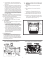
3. AIR DISTRIBUTION SYSTEM
SIZING & DESIGN
The Installer of this Air Conditioner System must design the
air distribution system for his particular application. Several
requirements for this system MUST be met for the Air
Conditioner to operate properly. These requirements are as
follows:
A. Roof cavity thickness must be between 2.00" to 5.50".
This distance is measured between roof and ceiling
surface.
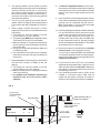
FIG. 1
AIR CONDITIONER DIMENSIONS
(On Top of Vehicle)
5-1/4”
18"
7-5/8”
14-7/8”
7-5/8”
KEEP THIS AREA FREE OF OBSTRUCTIONS
REAR
OF
UNIT
REAR
OF
UNIT
14-1/4" x 14-1/4”
(±1/8) OPENING
14-1/4" x 14-1/4”
(±1/8) OPENING
1. PRECAUTIONS
Improper installation may damage equipment/
could endanger life, cause serious injury and/
or property damage.
A. Read Installation and operating instructions carefully
before attempting to start your air conditioner instal-
lation.
B. The Dometic Corporation will not be liable for any
damages or injury incurred due to failure in following
these instructions.
C. Installation must comply with the National Electrical
Code and any State or Local Codes or regulations.
D. DO NOT add any devices or accessories to this air
conditioner except those specifically authorized by
Dometic.
E. This equipment must be serviced by qualified person-
nel and some states require these people to be
licensed.
2. CHOOSING LOCATION FOR THE
AIR CONDITIONER
This air conditioner is specifically designed for installation on
the roof of a recreational vehicle (RV).
A. For One Unit Installation:
The air conditioner should be mounted slightly forward
of center (front to back) and centered from side to side.
B. For Two Unit Installations:
Install one air conditioner 1/3 and one air conditioner
2/3s from front of RV and centered from side to side.
INSTALLATION INSTRUCTIONS

5
B. The total Cross-Sectional Discharge Area of outlet ducts
from the Plenum Area under the Air Conditioner must be
21.0 sq. in.
C. Duct Sizing Requirements as follows:
Min. Max.
1. Duct Depth 1-1/2" 2-1/4"
2. Duct Width 7.00"
3. Total Duct Length 12 ft. 36 ft.
4. Duct Length (Short Run) 1/3 Total Length
D. Register Requirements as follows:
Min. Max.
1. Distance from Duct End 5" 8"
2. Distance from End of Elbow 15"
3. Distance between Registers 24"
4. Total Number Required/AC 4 8
5. Number required per Run/AC 2
6. Free Area per Register 14 sq. in.
E. The Duct material must meet or exceed any agency or
RVIA Standard that may be in existence at the time the
RV is produced.
It is the responsibility of the installer to in-
sure the duct-work will not collapse or bend
during and after the installation. The
Dometic Corporation will not be liable for
roof structural or ceiling damage due to im-
properly insulated, sealed or collapsed
duct-work.
F. All Discharge Air Ducts must be properly insulated
to prevent condensation from forming on their
surfaces or adjacent surfaces during operation of
the Air Conditioner or heat pump. This insulation
must be R-7 minimum.
G. Ducts and their joints must be sealed to prevent
condensation from forming on adjacent surfaces
during operation of the Air Conditioner.
H. Return Air Opening must have 40 sq. in. minimum
free area including the filter.
I. Return Air to the Air Conditioner must be filtered to
prevent dirt accumulation on Air Conditioner Cooling
surface.
J. Total System Pressure must be between 0.40 to
1.10 in.W.C.
This is determined with the Air Conditioner Blower
operation on High Speed and Return Air Filter and
Grille in place.
4. AIR DISTRIBUTION SYSTEM
INSTALLATION
The Dometic Corporation recommends the basic configuration
shown on page 6 for installing this Air Conditioner System. We
have found by testing, that this configuration works best in most
applications of this Air Conditioner System.
It is the responsibility of the Installer of this System to review
each RV floor plan and determine the following:
A. Duct size
B. Duct layout
C. Register size
D. Register locations
E. Thermostat location.
These items must be determined in conjunction with the Air
Distribution System Sizing and Design Requirements listed in
Section 3 of this manual.
Important: Alternate configurations and methods may
be used which still allow the air conditioner to operate
properly. However, these alternate configurations and
methods must be approved by The Dometic Corporation
in writing.
The following instructions are based upon the use of
Dometic Return Air Kit No. 3105007 or 3105935. The
electronic control kit has mounting bolts supplied for use with
this Kit.
A. Before preparing the ceiling opening, the type of system
options must be decided upon. If a remote sensor is to be
used, provision must be made for it. If the load shed option
(Energy Management System feature) is to be used, wires
must be run from the load shed control to the Dometic
A/C. If a furnace is to be connected, wires must be run from
the furnace to the Dometic A/C. Read all of the following
instructions before beginning the installation.
B. ROOF AND CEILING OPENING PREPARATION
1. A 14-1/4" x 14-1/4" (±1/8") opening must be cut
through the roof and ceiling of the RV. This opening
must be located between the roof and reinforcing
members.
There may be electrical wiring between the roof
and the ceiling. Disconnect 115 volt AC power
cord and the positive (+) 12 volt DC terminal at
the supply battery. Failure to follow this instruc-
tion may create a shock hazard causing death
or severe personal injury.
2. Mark a 14-1/4" x 14-1/4" (±1/8") square on the roof and
carefully cut the opening.
3. Using the roof opening as a guide, cut the matching
hole in the ceiling.

6
4. The opening created must be framed to provide
adequate support and prevent air from being drawn
from the roof cavity. Lumber 3/4" or more in thick-
ness must be used. Remember to provide an en-
trance hole for power supplies, furnace wiring, 4-
conductor control cable, remote sensing and load
shed options as desired.
5. The 14-1/4" (±1/8") opening is part of the return air
system of the Air Conditioner and must be finished
in accordance with NFPA Standard 501C Section
2.7.
6. Route a copper 12 AWG, with ground, 115 VAC
supply line from the fuse or circuit breaker box to the
roof opening.
a. This supply line must be located in the front
portion of the 14-1/4" (±1/8") opening.
b. The power supply MUST be on a separate 15 amp
Time Delay Fuse or HACR Circuit Breaker.
c. Make sure at least 15" of supply wire extends into
the roof opening. This ensures easy connection at
the Junction Box.
d. Wiring must comply with all National, State and
Local Wiring Codes.
e. Use a steel sleeve and a grommet or equivalent
methods to protect the wire where it passes into
the opening.
7. Route a dedicated 12 VDC supply line (18-22 AWG)
from the RV's Converter or Battery to the roof
opening.
a. This supply line must be located in the front
portion of the 14-1/4" (±1/8") opening.
b. Make sure that at least 15" of supply wire extends
into the roof opening.
c. In a multiple zone installation, this wiring is
required in only one of the 14-1/4" (±1/8")
openings.
8. If a Remote Temperature Sensor is to be used ,
the connector end must be routed to the roof opening
of the system which it will control. Make sure that at
least 15" of the sensor cable extends into the roof
opening.
9. If a furnace is to be controlled by the system, the two
furnace thermostat leads must be routed to the roof
opening of the air conditioner that will control it.
Make sure at least 15" of the furnace thermostat
wires extend into the roof opening.
10. If an Energy Management System- EMS (load shed)
is to be used with the control, two wires must be
routed to the roof opening of the zone to be man-
aged. The signal required for this function is a
normally open relay contact. When the EMS calls
for the compressor to shut off, the relay contacts
should close. Make sure that at least 15" of the EMS
wires extend into the roof opening.
11. Route a 4-conductor control cable from the Comfort
Control Center mounting position into the
14-1/4" (±1/8") roof opening. Make sure that at least
15" of the wire extends into the roof opening and 6"
extend from the wall at the mounting position of the
Comfort Control Center.
12. In the event that other A/C's are to be installed
(additional zones) an additional 4-conductor control
cable must be routed to the other A/C's. Make sure
that at least 15" of the wire extends into each of the
roof openings. See FIG. 3.
13. If an automatic generator start kit (AGS) will be
installed, a 4-conductor control cable must be
routed from the last air conditioner to location of
AGS kit. Follow AGS kit instructions for installation.
REGISTERS
4 MIN. 8 MAX. (Per A/C)
14 SQ. IN. FREE AREA
PER REGISTER
14-1/4" (±1/8")
ROOF OPENING
ROOF RAFTERS
SHORT RUN DUCT MIN. 1/3
TOTAL DUCT LENGTH
AIR CONDITIONER
VEHICLE
FRONT
FIG. 2
TOTAL OUTLET
AIR AREA MINIMUM:
21.0 sq. in.
DUCTS MIN. MAX.
DEPTH 1-1/2" 2-1/4"
WIDTH 7"
TOTAL LENGTH 12' 36'

7
FRAME
14-1/4" (±1/8”)
OPENING
AC POWER
SUPPLY WIRE
DUCT
FRAME
FRAME
CCC, CONTROL CABLE(S)
or 7-Wire Analog Cable LOW VOLTAGE WIRES:
12VDC
Furnace
Load Shed
Sensors
DUCT
ROOF
INSULATION
DUCT TO REAR CEILING
DUCT TO FRONT
14-1/4" (±1/8”)
OPENING
INSULATION
SIDE VIEW
(TOWARD BACK OF RV)
TOP VIEW
(BACK OF RV)
C. AIR DISTRIBUTION DUCT
INSTALLATION
Install the Air Distribution Ducts in the RV Roof Cavity. The
Distribution System must meet:
1. RVs requirements
2. System requirements listed in Section 3 of this
Manual.
Terminate the start of the Duct at the back edge of the
14-1/4" (±1/8") opening previously cut.
FIG. 3
FIG. 4
REAR REMOTE SENSOR
(Required with Second
Air Conditioner)
REAR REMOTE SENSOR
(Required with Second
Air Conditioner)
14-1/4" x 14-1/4"
(±1/8”) OPENING
14-1/4" x 14-1/4"
(±1/8”)OPENING
14-1/4" x 14-1/4"
(±1/8”) OPENING
14-1/4" x 14-1/4"
(±1/8”)OPENING
OPTIONAL
FURNACE
OPTIONAL
FURNACE
FURNACE
2 WIRES
FURNACE
2WIRES
OPTIONAL FRONT
REMOTE SENSOR
OPTIONAL FRONT
REMOTE SENSOR
12V DC INPUT
2 WIRES
12V DC INPUT
2WIRES
FURNACE
FURNACE
4-CONDUCTOR
CONTROL CABLE
4-CONDUCTOR
CONTROL CABLE
BREAKER BOX
BREAKER BOX
115V AC
REAR A/C
115V AC
REAR A/C
4-CONDUCTOR
CONTROL CABLE
4-CONDUCTOR
CONTROL CABLE
115V AC
FRONT A/C
115V AC
FRONT A/C
FURNACE
2 WIRES
FURNACE
2WIRES
DOMETIC COMFORT
CONTROL CENTER
DOMETIC COMFORT
CONTROL CENTER

8
5. DOMETIC COMFORT CONTROL
CENTER & CABLE
INSTALLATION
A. LOCATION
1. If the system is to be used WITHOUT a Remote
Temperature Sensor, the proper location of the
Comfort Control Center is very important to
ensure that it will provide a comfortable RV tempera-
ture. Observe the following rules when selecting a
location.
a. Locate the Comfort Control Center 54" above
the floor.
b. Install the Comfort Control Center on a parti-
tion, not on an outside wall.
c. NEVER expose it to direct heat from lamps, sun
or other heat producing items.
d. Avoid locations close to doors that lead outside,
windows or adjoining outside walls.
e. Avoid locations close to supply registers and the
air from them.
2. If the system is to be used WITH a Remote
Temperature Sensor in ALL zones, the comfort
Control Center may be mounted anywhere that is
convenient in the coach. Try to avoid hard to reach
and hard to see areas.
a. Refer to the instructions provided with the Re-
mote Temperature Sensor for details of instal-
lation.
3. A 3/8" diameter hole will be needed to route the
control cable through the wall.
B. CONTROL CABLE INSTALLATION
A 4-conductor control cable must be routed from the roof
opening to the Comfort Control Center.
1. Choose the shortest, most direct route from the 14-
1/4" (±1/8") opening to the Comfort Control Cen-
ter location selected. Leave 6" of cable extending
through the wall.
2. The cable that should be used is a flat, 4-conductor
telephone cable.
3. The cable must be terminated with two (2) RJ-11
telephone connectors. Refer to the crimp tool manu-
facturer for crimping instructions.
Important: RJ-11 connectors must be installed as
shown in FIG. 5A.
C. COMFORT CONTROL CENTER INSTALLATION
1. Carefully remove the base plate from the Comfort
Control Center. This may be accomplished by
inserting a screwdriver under the tab on the bottom
edge of the front cover and gently prying. (See
FIG.6).
2. Insert the control cable through the hole in the base
plate and mount the plate to the wall with the two
screws provided.
3. Install the control cable RJ-11 connector into the
back of the Comfort Control Center and gently
press onto the base plate.
6. PLACING THE AIR CONDITIONER
ON THE ROOF
A. Remove the Air Conditioner from the carton
and discard.
B. Place the Air Conditioner on the roof.
This unit weighs approximately 100
pounds.To prevent back injury, use a me-
chanical hoist to place Air Conditioner on roof.
C. Lift and place the unit over the prepared opening using
the gasket on unit as a guide. The blunt end goes
toward the rear of the RV.
FIG. 5A
FIG. 6
FIG. 7
BE KIND -
RECYCLE ALL CARD-
BOARD
Insert Screwdriver
under Tab
Insert Screwdriver
under Tab
MODE
FAN
UP
DOWN
OFF ON
OFF ON
ZONE
TEMP
TEMP
FIG. 5B

9
5. Take the ceiling template and hold up to the 14-1/4"
(±1/8") opening.
6. Start each mounting bolt through the ceiling tem-
plate and up into the unit base pan by hand.
7. Evenly tighten mounting bolts to a torque of 40 to 50
Inch Pounds.
If bolts are left loose there may not be an ad-
equate roof seal or if over tightened, damage
may occur to the air conditioner base or ceil-
ing template. Tighten to torque specifications
listed in this manual.
This will compress the roof gasket to approximately
1/2". The bolts are self locking so over tightening is
not necessary.
8. Install wood screw in each end of ceiling template.
This insures a tight fit of return air cover to ceiling.
Do not slide the unit. This may damage the
neoprene gasket attached to the bottom and
create a leaky installation.
D. Place the Electronic Control Kit and the Return Air Cover
Kit inside the RV. These cartons contain mounting
hardware for the air conditioner and will be used inside
the RV.
This completes the outside work. Minor adjustments can be
done from the inside of the RV if required.
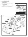
7. INSTALLATION OF AIR
CONDITIONER
A. INSTALLATION OF CEILING TEMPLATE
Note: 3105007 Template and Cover are shown. 3105935 Kit
installation is the same except Kit has opening for discharge
of conditioned air directly from unit.
1. Check gasket alignment of the Air Conditioner over
roof opening and adjust if necessary. Unit may be
moved from below by slightly lifting and sliding.
2. Reach up into the return air opening of the Air
Conditioner and pull the unit electrical cord down for
later connection.
3. Remove Return Air Cover and Ceiling Template from
the 3105007 or 3105935, return air cover kit carton.
4. Locate 1/4" unit mounting bolts in the Electronic
Control Kit package.
FRONT
FIG. 8
Return Air Grille
Return Air
Cover
Ceiling
Template
Divider
Plate
FIG. 10
FIG. 9

10
Note: Do not cover up unit rating plate.
C. INSTALLATION OF ELECTRONIC CONTROL KIT
1. Terminate the 4-conductor control cable(s) protrud-
ing into the 14-1/4" (±1/8") roof opening. The cable(s)
must be terminated with a RJ-11 telephone connec-
tor. Refer to the crimp tool manufacturer for crimping
instructions.
Important: RJ-11 connectors must be installed as
shown in FIG. 5A.
Note: Pre-assembled telephone cable may not work. RJ-11
connection MUST be installed so wire colors are the same
on both ends.
2. Remove the screw holding the junction box cover to
the Electronic Control Kit. Remove the cover.
3. Insert the Freeze Control Sensor approximately
1" into the fins of the evaporator coil as shown in FIG.
14. Bend fins over sensor to secure in place.
4. Plug the unit electrical cord into the mating connec-
tor on the Electronic Control Kit. These connec-
tors are polarized and will easily snap together. DO
NOT FORCE.
5. Plug the control cable(s) into the telephone jack(s)
visible on the side of the Electronic Control Kit. (It
does not matter which one.)
B. INSTALLATION OF DIVIDER PLATE
1. Measure the ceiling to roof thickness:
a. If distance is 2.00" - 3.75", remove perforated tab
from Divider Plate.
b. If distance is 3.75" - 5.50", remove no tabs.
2. Remove the backing paper from double sided tape
located on Ceiling Template.
3. Place Divider Plate up to bottom of Air Conditioner
base pan firmly. The foam tape on the divider plate
must seal to bottom of base pan.
Note: The adhesive on double sided tape is extremely
sticky. Divider Plate must be properly positioned before
pressing in place.
4. With slight pressure, push the divider plate against
the exposed double sided tape on ceiling template.
5. Locate 1/8" x 7" x 18" self-adhesive insulation
supplied with the Return Air Kit.
6. Remove the backing paper from the insulation and
carefully stick onto the ceiling template divider
panel.
Note: The adhesive on insulation is extremely sticky.
Be sure part is located where desired before pressing
into place. We recommend pulling off part of backing
paper, locating part and then remove backing paper as
insulation is pressed into place.
a. Excess width is intended to seal the divider
plate to the sides of the 14-1/4" (±1/8") open-
ing. This is to prevent cold discharge air from
circulating into the Air Conditioner return air
opening.
b. If the insulation is too high, stick the excess
height of insulation to the Air Conditioner base
pan.
FIG. 11
FIG. 12
FIG. 13
FIG. 14 FREEZE CONTROL
Freeze Control with
wires to the right side
Remove
Hang
Tag
Insert Freeze
Control Sensor
at a slight angle
between bottom
coil approximately 1”
Freeze control
sensor
Bend fins over
sensor to hold
in place

11
wire connectors to the supply wiring to assure they do
not vibrate off.
3. Tighten screws on strain relief connector being care-
ful not to pinch and cut into the insulation on power
supply leads.
4. Push excess wires into junction box.
9. SYSTEM RESET, CONFIGURATION
& CHECKOUT
Now that the system is installed, it is necessary to check all
operations and then configure the electronics.
Refer to the Operating manual for a description of the air
conditioner operation.
A. ELECTRONIC CONTROL KIT CONFIGURATION
Depending on the equipment options installed by the
recreational vehicle manufacturer, the appropriate dip
switches will need to be switched to the "ON" position.
See FIG. 16. Placing the switch in the "ON" position
selects that option.
Note: Dip switches are in the "OFF" position when shipped
from the factory.
1. Zone selection - when two or more units are installed
and controlled by one Comfort Control Center, the
second unit becomes Zone 2, the third unit Zone 3 and
the fourth unit Zone 4. The appropriate zone dip switch
must be set in each electronic control kit for Zone 2, 3
and 4.
6. Locate the Electronic Control Kit on the ceiling
template.
7. Drive two #10 x 3/8 blunt point Phillips head screws
(provided in the parts package) through the ceiling
template into the holes in the Electronic Control
Kit to hold it in place.
8. WIRING OF SYSTEM
A. CONNECTION OF LOW VOLTAGE WIRES
Disconnect the positive (+) 12 volt DC termi-
nal at the supply battery. Damage to equip-
ment could occur if the 12 volt DC is not shut
off.
1. Route the Remote Temperature Sensor cable,
if applicable, through the grommet in the Elec-
tronic Control Kit and attach it to the connector
that matches its color. (See FIG. 15)
2. Connect the previously run 12 VDC to the red and
black wires protruding from the Electronic Con-
trol Kit. (In multiple zone installations, this needs
to be done at only one zone.) Connect +12 VDC to
the red wire; 12 VDC to the black wire.
3. Connect the previously run furnace thermostat
wires (if applicable) to the blue wires protruding
from the Electronic Control Kit. The polarity of
these connections does not matter.
4. Connect the previously run Energy Management
System wires for load shed (if applicable) to the
yellow wires protruding from the Electronic Con-
trol Kit. The polarity of these connections does not
matter.
B. CONNECTION OF 115 VOLT POWER SUPPLY
Disconnect 115 volt AC. Failure to follow
these instructions could create a shock haz-
ard causing death or severe personal injury.
1. Route the previously run power supply line through
the Romex Connector and into the Electronic
Control Kit Junction Box.
This appliance is equipped with a 3-wire
(grounded) system for protection against
shock hazard. Make sure that the appliance
is wired into a properly grounded 115 volt AC
circuit and the polarity is correct. Failure to
do so could result in death, personal injury
or damage to the equipment.
2. Connect the white to white; black to black; and
green to green or bare copper wire using appropri-
ate sized twist wire connectors. Tape the twist
FIG. 15
FIG. 16
12 34 5
HEAT STRIP
ZONE 2
ZONE 3
ZONE 4
FURNACE
DIP
SWITCHES
DIP
SWITCHES
ON
678
DIFFERENTIAL
STAGE
GEN START

12
UNIT FIELD WIRING DIAGRAM (A/C) ELECTRONIC FIELD WIRING DIAGRAM
Return
Ai r Cove
r
Hole
Plugs
Return
Ai r
Grille
FIG. 17
2. Furnace selection - when a furnace has been con-
nected to a zone, place the furnace dip switch "ON"
for that zone.
3. Differential - differential is the temperature difference
between the "ON/OFF" cycle of the thermostat. The
normal differential is preset in the circuit board with
the dip switch set to the "OFF" position. In some
situations, it may be necessary to decrease the Dif-
ferential. The location of the thermostat may create a
condition where the normal Differential will not main-
tain your comfort zone. If this occurs, the Differential
can be shortened by placing the Differential dip switch
to the "ON" position.
Note: Setting the Differential dip switch should only be
required when installation conditions are less than desirable
and is not covered under the limited warranty.
4. Stage selection - stage is not used on these units.
Leave in the "OFF" position.
5. Gen start selection - leave in the "OFF" position.
B. SYSTEM RESET
After setting the dip switches in the electronic control
kit, do a system reset.
1. Turn the ON/OFF switch to the "OFF" position.
2. Simultaneously depress and hold the MODE and
ZONE push-buttons while turning the ON/OFF switch
to "ON". FF should appear in LCD display until the
mode and zone push-buttons are released.
3. When a dip switch is turned on after initial configu-
ration, a system reset will need to be done before the
Comfort Control Center will recognize the updated
selection. Replace the junction box cover onto the
Electronic Control Kit.
C. SYSTEM CHECKOUT
Verify that all features of the installed system work.
Check fan speeds, cooling mode, furnace (if connected)
etc. If the features do not work, check all wiring and
confirm that the correct options have been selected on
the Electronic Control Box. See Comfort Control Cen-
ter Operating Instructions.
10. INSTALLATION OF RETURN AIR
COVER
A. Remove Return Air Grille from the Return Air
Cover.
B. Place the Return Air Cover up to Ceiling Tem
plate.
C. Install Cover to Template with #8 x 3/8" blunt
point Phillips head screws provided (6 required).
D. Reinstall Return Air Grille into Return Air Cover.
E. Install two (2) hole plugs into screw holes in back
of return air grille. Align tabs with mating notches
and snap filter into place. (See FIG. 17)
YEL
YEL
NO
COM
NO
COM
RELAY
RELAYK1
K6
1
2
3
1
2
3
4
5
6
BLK
GRN/YEL
WHT
GRY
WHT
WHT GRN/YEL
BLU
BLK
BLK
YEL
RED P5
P4
FIELD WIRING
OPTIONAL
OPTIONAL
WIRING
WIRING
FACTORY WIRING
LINE SPLICE
LINE SPLICE
3106515.012
OPTIONAL
OPTIONAL
E OR M TE
TO OPT
TO OPT
ELEC HEAT
ELEC HEAT
RJ-11
CABLE
CABLE
TO COMFORT
TO COMFORT
CONTROL CENTER
P1
P2
BLU
BLU
BLK
RED
ELEC CONN
ELEC CONN
FROM A/C
P6
12V +
12V +
12V -
12V -
LOAD SHED
LOAD SHED
FURNACE
FURNACE
LOAD SHED
LOAD SHED
SENSOR
T1
T2
T3
P3
FREEZE
FREEZE
CONTROL
*
*
SENSOR
SENSOR
AMBIENT
AMBIENT
*
3AMP
FUSE
F1
*
**
-NOT USED ON SOME MODELS
-NOT USED ON SOME MODELS
-HEATPUMP MODELS ONLY
-HEATPUMP MODELS ONLY
USE COPPER CONDUCTORS ONLY
USE COPPER CONDUCTORS ONLY
115 VAC 1o
60 HZ
60 HZ
T5
BLK
-
 1
1
-
 2
2
-
 3
3
-
 4
4
-
 5
5
-
 6
6
-
 7
7
-
 8
8
-
 9
9
-
 10
10
-
 11
11
-
 12
12


Dometic Duo Therm Brisk Air 59529_59530 Quick Cool Roof Top Air Conditioners Installation guide
- Category
- Split-system air conditioners
- Type
- Installation guide
Ask a question and I''ll find the answer in the document
Finding information in a document is now easier with AI
Related papers
-
Dometic 600315.326 Installation Instructions Manual
-
Dometic Duo therm 3103875 Center Duct Kit For Use Installation guide
-
-
-
-
-
-
-
-