Page is loading ...

7R00370-H01
Revision B
October 2017
FPD for Gas Chromatographs
Hardware Reference Manual

Introduction
NOTICE
ROSEMOUNT (“SELLER”) SHALL NOT BE LIABLE FOR TECHNICAL OR EDITORIAL ERRORS IN THIS MANUAL OR
OMISSIONS FROM THIS MANUAL. SELLER MAKES NO WARRANTIES, EXPRESSED OR IMPLIED, INCLUDING THE IMPLIED
WARRANTIES OF MERCHANTABILITY AND FITNESS FOR A PARTICULAR PURPOSE, WITH RESPECT TO THIS MANUAL
AND, IN NO EVENT, SHALL SELLER BE LIABLE FOR ANY SPECIAL OR CONSEQUENTIAL DAMAGES INCLUDING, BUT NOT
LIMITED TO, LOSS OF PRODUCTION, LOSS OF PROFITS, ETC.
PRODUCT NAMES USED HEREIN ARE FOR MANUFACTURER OR SUPPLIER IDENTIFICATION ONLY AND MAY BE
TRADEMARKS/REGISTERED TRADEMARKS OF THESE COMPANIES.
THE CONTENTS OF THIS PUBLICATION ARE PRESENTED FOR INFORMATIONAL PURPOSES ONLY, AND WHILE EVERY
EFFORT HAS BEEN MADE TO ENSURE THEIR ACCURACY, THEY ARE NOT TO BE CONSTRUED AS WARRANTIES OR
GUARANTEES, EXPRESSED OR IMPLIED, REGARDING THE PRODUCTS OR SERVICES DESCRIBED HEREIN OR THEIR USE
OR APPLICABILITY. WE RESERVE THE RIGHT TO MODIFY OR IMPROVE THE DESIGNS OR SPECIFICATIONS OF SUCH
PRODUCTS AT ANY TIME.
SELLER DOES NOT ASSUME RESPONSIBILITY FOR THE SELECTION, USE, OR MAINTENANCE OF ANY PRODUCT.
RESPONSIBILITY FOR PROPER SELECTION, USE, AND MAINTENANCE OF ANY SELLER PRODUCT REMAINS SOLELY WITH
THE PURCHASER AND END-USER.
THE EMERSON LOGO IS A TRADEMARK AND SERVICE MARK OF EMERSON ELECTRIC CO. ROSEMOUNT IS A TRADEMARK
OF ONE OF THE EMERSON FAMILY OF COMPANIES.
©2017
ROSEMOUNT
HOUSTON, TX
USA
All rights reserved. No part of this work may be reproduced or copied in any form or by any means–graphic, electronic,
or mechanical–without first receiving the written permission of Rosemount Houston, Texas, U.S.A.

WARRANTY
LIMITED WARRANTY: Subject to the limitations contained in Section 2 herein and except as otherwise expressly
provided herein, Rosemount (“Seller”) warrants that the firmware will execute the programming instructions
provided by Seller, and that the Goods manufactured or Services provided by Seller will be free from defects in
materials or workmanship under normal use and care until the expiration of the applicable warranty period. Goods are
warranted for twelve (12) months from the date of initial installation or eighteen (18) months from the date of
shipment by Seller, whichever period expires first. Consumables and Services are warranted for a period of 90 days
from the date of shipment or completion of the Services. Products purchased by Seller from a third party for resale to
Buyer (“Resale Products”) shall carry only the warranty extended by the original manufacturer. Buyer agrees that Seller
has no liability for Resale Products beyond making a reasonable commercial effort to arrange for procurement and
shipping of the Resale Products. If Buyer discovers any warranty defects and notifies Seller thereof in writing during
the applicable warranty period, Seller shall, at its option, promptly correct any errors that are found by Seller in the
firmware or Services, or repair or replace F.O.B. point of manufacture that portion of the Goods or firmware found by
Seller to be defective, or refund the purchase price of the defective portion of the Goods/Services. All replacements or
repairs necessitated by inadequate maintenance, normal wear and usage, unsuitable power sources, unsuitable
environmental conditions, accident, misuse, improper installation, modification, repair, storage or handling, or any
other cause not the fault of Seller are not covered by this limited warranty, and shall be at Buyer's expense. Seller shall
not be obligated to pay any costs or charges incurred by Buyer or any other party except as may be agreed upon in
writing in advance by an authorized Seller representative. All costs of dismantling, re-installation and freight and the
time and expenses of Seller's personnel for site travel and diagnosis under this warranty clause shall be borne by Buyer
unless accepted in writing by Seller. Goods repaired and parts replaced during the warranty period shall be in warranty
for the remainder of the original warranty period or ninety (90) days, whichever is longer. This limited warranty is the
only warranty made by Seller and can be amended only in a writing signed by an authorized representative of Seller.
Except as otherwise expressly provided in the Agreement, THERE ARE NO REPRESENTATIONS OR WARRANTIES OF ANY
KIND, EXPRESSED OR IMPLIED, AS TO MERCHANTABILITY, FITNESS FOR PARTICULAR PURPOSE, OR ANY OTHER
MATTER WITH RESPECT TO ANY OF THE GOODS OR SERVICES.
It is understood that corrosion or erosion of materials is
not covered by our guarantee.
LIMITATION OF REMEDY AND LIABILITY: SELLER SHALL NOT BE LIABLE FOR DAMAGES CAUSED BY DELAY IN
PERFORMANCE. THE SOLE AND EXCLUSIVE REMEDY FOR BREACH OF WARRANTY HEREUNDER SHALL BE LIMITED TO
REPAIR, CORRECTION, REPLACEMENT, OR REFUND OF PURCHASE PRICE UNDER THE LIMITED WARRANTY CLAUSE IN
SECTION 1 HEREIN. IN NO EVENT, REGARDLESS OF THE FORM OF THE CLAIM OR CAUSE OF ACTION (WHETHER BASED
IN CONTRACT, INFRINGEMENT, NEGLIGENCE, STRICT LIABILITY, OTHER TORT OR OTHERWISE), SHALL SELLER'S
LIABILITY TO BUYER AND/OR ITS CUSTOMERS EXCEED THE PRICE TO BUYER OF THE SPECIFIC GOODS
MANUFACTURED OR SERVICES PROVIDED BY SELLER GIVING RISE TO THE CLAIM OR CAUSE OF ACTION. BUYER
AGREES THAT IN NO EVENT SHALL SELLER'S LIABILITY TO BUYER AND/OR ITS CUSTOMERS EXTEND TO INCLUDE
INCIDENTAL, CONSEQUENTIAL, OR PUNITIVE DAMAGES. THE TERM “CONSEQUENTIAL DAMAGES” SHALL INCLUDE,
BUT NOT BE LIMITED TO, LOSS OF ANTICIPATED PROFITS, LOSS OF USE, LOSS OF REVENUE, AND COST OF CAPITAL.

Introduction

Table of Contents
i
Table of Contents
1 Introduction .......................................................................... 1
1.1 Theory of operation ........................................................................................................2
1.2 Equipment description ...................................................................................................4
1.2.1
Model 500 FPD ...................................................................................................6
1.2.2
Model 700 FPD ...................................................................................................9
1.2.3
Model 700 FPD front entry ............................................................................... 12
1.2.4
Model 700XA FPD ............................................................................................ 13
1.2.5
Model 700XA FPD front entry .......................................................................... 14
1.2.6
Model 1500XA FPD .......................................................................................... 15
1.3 Glossary ...................................................................................................................... 16
2 Setup ................................................................................... 19
2.1 Gas connections .......................................................................................................... 19
2.2 Environmental Considerations ..................................................................................... 19
2.3 Utility gases ................................................................................................................. 19
2.4 Venting ....................................................................................................................... 20
3 Operation and maintenance.................................................. 23
3.1 Operation .................................................................................................................... 23
3.1.1
Igniting the flame manually ............................................................................. 24
3.2 Maintenance ............................................................................................................... 25
3.3 Troubleshooting.......................................................................................................... 26
A Appendix A: Drawings .......................................................... 29
A.1 Model 500 FPD drawings ............................................................................................. 29
A.2 Model 700 FPD drawings ............................................................................................. 30
A.3 Enclosure threaded entry details ................................................................................. 51
B Appendix B: Manufacturer’s manuals ..................................... 57
B.1 Flame Photometric Detector Operation Manual ........................................................... 58
B.2 GUB FPD 118500-3411 GUB ........................................................................................ 67
C Appendix C: Spare Parts List ................................................ 107


Introduction
1
1 Introduction
The flame photometric detector (FPD) that you have received is factory-engineered to be used in
conjunction with all Rosemount gas chromatographs. The FPD can be used as a solitary detector to
measure low levels of sulfur compounds in natural gas or as a secondary detector in conjunction
with a thermal conductivity detector (TCD) that allows the GC to analyze the full range of
components present in a natural gas sample, including sulfur compounds.
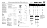
A. Flame photometric detector (FPD)
B. Photomultiplier tube
C. Flame cell
D. Electrometer board
An FPD (A) typically consists of the following major components:
The flame cell (C) - Located in the lower enclosure, the flame cell has connections for fuel gas,
hydrocarbon-free air, sample injection (process gas plus nitrogen carrier), and an exhaust pipe. It is
fitted with an RTD to monitor the temperature when running, and an ignitor to light the fuel gas.
The photomultiplier tube (B) - Located in the lower enclosure, the photomultiplier tube contains the
sensors that measure the light that is emitted from the flame cell during operation. It has one signal
lead and one high voltage wire that take the signal from the detector to the electrometer board
and provide the power for ignition. The leads are co-axial type cables.
Figure
1-1: Flame Photometric Detector (FPD)

Introduction
2
The electrometer board (D) - Located in the upper enclosure, the electrometer board amplifies and
processes the signal data from the detector, and sends it to the CPU board on the GC. It also
provides the ignition circuit, controls the re-light function, and generates the flame out alarm.
1.1 Theory of operation
NOTICE
See also Section 1.3 of this manual, for definitions of some of the terminology used in the following
explanations.
The detection system in the FPD uses the reactions of sulfur components in a hydrogen or air flame
as a source for analytical detection. The source of the FPD's signal is derived from the light
produced by an excited molecule created in the flame's combustion, which is a photochemical
process called chemiluminescence.
A thermocouple is fitted to the flame cell to ensure that the flame is present. If the flame is not
detected, the electrometer shuts off the hydrogen to the flame cell. It then supplies a voltage to
the igniter, waits five seconds and opens the hydrogen shut off valve. The electrometer will make
ten ignition attempts if necessary. If it is not successful, then the hydrogen is shut off, an alarm is
triggered on the GC and the unit awaits attention from the operator.
NOTICE
To ignite the flame manually, see Section 3.1.1.
The signal is sent from the PMT to the electrometer to be amplified. The electrometer also provides
the PMT with the high voltage it requires to operate the auto re-light circuits.1.3

Introduction
3
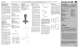
1.
Carrier gas only at the detector
2.
First component begins to elute from the columns and is sensed by the detector.
3.
Peak concentration of first component.
4.
The second component begins to elute from the columns and is sensed by the detector.
5.
Peak concentration of the second component.
Figure
1-2: Elution of Components

Introduction
4
The signal is then sent to the preamplifier board for further amplification. In addition, the
preamplifier converts each voltage signal to a value that is proportional to the concentration of the
component detected in the gas sample. The preamplifier provides four different gain channels as well
as compensation for baseline drift. The signals are sent to the GC for computation or for viewing on
a PC monitor or local operator interface (LOI).
While the GC is in Idle mode, prior to injecting a sample, the detector is exposed to pure carrier gas.
In this condition, the output from the detector is electrically nulled. The detector output is set to 1
mV DC. This is measured on the red and black terminals on the preamplifier board, and adjusted
using the potentiometer (R38) on the electrometer PCB.
1.2 Equipment description
FPDs are available in the following configurations:
• Model 500 FPD
• Model 700 FPD
• Model 700 FPD Front Entry
• 700XA FPD
• 700XA FPD Front Entry
• 1500XA FPD
NOTICE
The Front Entry configurations include an additional frame to allow all the FPD enclosures to be
mounted on the front of the unit. This allows the unit to be located close to a wall because no rear
access is required for installation or maintenance.
All configurations are ATEX-certified. The differences between the configurations are detailed in
later sections of this chapter.

Introduction
5
The FPD used with the Model 500, 700, and 700XA gas chromatographs has the following
hazardous area certification markings:

Introduction
6
1.2.1
Model 500 FPD
The Model 500 FPD module consists of three Exd GUB enclosures mounted on a frame, plus an Exd
solenoid that acts as a hydrogen shut-off valve. The enclosures contain the following:
• Electrometer assembly in GUB 5 enclosure
• Flame cell and photometric detector tube in GUB 5 enclosure
• Transformer (either 230/110 Vac or 110/110 Vac) in GUB 4 enclosure
• Hydrogen shut-off valve
Figure
1-3: Model 500 FPD

Introduction
7
A. Electrometer assembly
B. Flame cell and FP tube
C. H
2
shut off valve
D. Transformer
Place the FPD module as close as possible to its partner GC to minimize the length of sample tubing
between them, and therefore to keep the cycle time as short as possible.
The tubing required to operate the FPD flame cell is 1/16 in. OD 0.010 in. ID. All tubing enters the
GUB enclosure containing the flame cell via a specially designed tubing gland. All internal fittings
are Swagelok double ferrule type compression fittings.
Figure
1-4: Model 500 FPD Enclosures

Introduction
8
Figure
1-5: Specialized Tubing Gland

Introduction
9
1.2.2
Model 700 FPD
The Model 700 FPD module consists of four Exd GUB enclosures mounted on a frame, plus an Exd
solenoid valve that acts as a hydrogen shut-off valve. The Model 700 FPD requires an additional
enclosure to house temperature control equipment that on a Module 500 GC is available internally.
Figure
1-6: Model 700 FPD

Introduction
10
The enclosures contain the following:
• Electrometer assembly in GUB 5 enclosure
• Flame cell and photometric detector tube in GUB 5 enclosure
• PID Temperature controller and relay
• Transformer (either 230/110 Vac or 110/110 Vac) in GUB 4 enclosure
• Hydrogen shut-off valve
Place the FPD module as close as possible to its partner GC to minimize the length of sample tubing
between them, and therefore to keep the cycle time as short as possible.
The tubing required to operate the FPD flame cell is 1/16 in. OD 0.010 in. ID. All tubing enters the
GUB enclosure containing the flame cell via a specially designed tubing gland. All internal fittings are
Swagelok double ferrule type compression fittings.
Figure
1-7: PID Temperature Controller and Relay

Introduction
11
Figure
1-8: Specialized Tubing Gland

Introduction
12
1.2.3
Model 700 FPD front entry
The Model 700 FPD front entry is comprised of the same components as the standard Model 700
FPD with an additional frame added to allow all the enclosures to be mounted on the front of the
unit. This allows the unit to be located close to a wall because no rear access is required for
installation or maintenance.
Figure
1-9: Model 700 FPD Front Entry

Introduction
13
1.2.4
Model 700XA FPD
The Model 700XA FPD consists of four explosion-proof enclosures mounted on a frame plus an
explosion-proof solenoid valve that acts as a hydrogen shut-off valve.
Figure
1-10: Model 700XA FPD

Introduction
14
The enclosures contain the following components:
• Electrometer assembly
• Flame cell and photometric detector tube
• Transformer, either a 230/110 Vac or a 110/110 Vac
• PID temperature controller and relay
• Hydrogen shut-off valve
Place the FPD as close as possible to its partner GC to minimize the length of sample tubing
between them, and keep the cycle time as short as possible.
The tubing size required to operate the FPD flame cell is 1/16 in. OD 0.010 in. ID. All tubing enters
the flame cell’s enclosure through a specially designed tubing gland. All internal fittings are
Swagelok double ferrule compression fittings.
1.2.5
Model 700XA FPD front entry
The Model 700XA FPD front entry is comprised of the same components as the standard Model
700XA FPD with an additional frame added to allow all the enclosures to be mounted on the front
of the unit. This allows the unit to be located close to a wall, because no rear access is required for
installation or maintenance.
Figure
1-11: Specialized Tubing Gland
/