Page is loading ...

Quick Start Guide
00825-0100-3404, Rev AA
May 2019
Rosemount
™
404
Contacting Conductivity Sensor

Notice
ROSEMOUNT
™
(“SELLER”) SHALL NOT BE LIABLE FOR TECHNICAL OR EDITORIAL ERRORS IN THIS
MANUAL OR OMISSIONS FROM THIS MANUAL. SELLER MAKES NO WARRANTIES, EXPRESSED OR
IMPLIED, INCLUDING THE IMPLIED WARRANTIES OF MERCHANTABILITY AND FITNESS FOR A
PARTICULAR PURPOSE, WITH RESPECT TO THIS MANUAL AND, IN NO EVENT, SHALL SELLER BE LIABLE
FOR ANY SPECIAL OR CONSEQUENTIAL DAMAGES INCLUDING, BUT NOT LIMITED TO, LOSS OF
PRODUCTION, LOSS OF PROFITS, ETC.
PRODUCT NAMES USED HEREIN ARE FOR MANUFACTURER OR SUPPLIER IDENTIFICATION ONLY AND
MAY BE TRADEMARKS/REGISTERED TRADEMARKS OF THESE COMPANIES.
THE CONTENTS OF THIS PUBLICATION ARE PRESENTED FOR INFORMATIONAL PURPOSES ONLY, AND
WHILE EVERY EFFORT HAS BEEN MADE TO ENSURE THEIR ACCURACY, THEY ARE NOT TO BE
CONSTRUED AS WARRANTIES OR GUARANTEES, EXPRESSED OR IMPLIED, REGARDING THE PRODUCTS
OR SERVICES DESCRIBED HEREIN OR THEIR USE OR APPLICABILITY. WE RESERVE THE RIGHT TO
MODIFY OR IMPROVE THE DESIGNS OR SPECIFICATIONS OF SUCH PRODUCTS AT ANY TIME.
SELLER DOES NOT ASSUME RESPONSIBILITY FOR THE SELECTION, USE, OR MAINTENANCE OF ANY
PRODUCT. RESPONSIBILITY FOR PROPER SELECTION, USE, AND MAINTENANCE OF ANY SELLER
PRODUCT REMAINS SOLELY WITH THE PURCHASER AND END-USER.
Warranty
1.
LIMITED WARRANTY: Subject to the limitations contained in Section 2 herein and except as
otherwise expressly provided herein, Rosemount
™
(“Seller”) warrants that the firmware will
execute the programming instructions provided by Seller and that the Goods manufactured
or Services provided by Seller will be free from defects in materials or workmanship under
normal use and care until the expiration of the applicable warranty period. Goods are
warranted for twelve (12) months from the date of initial installation or eighteen (18) months
from the date of shipment by Seller, whichever period expires first. Consumables and
Services are warranted for a period of 90 days from the date of shipment or completion of the
Services. Products purchased by Seller from a third party for resale to Buyer (“Resale
Products”) shall carry only the warranty extended by the original manufacturer. Buyer agrees
that Seller has no liability for Resale Products beyond making a reasonable commercial effort
to arrange for procurement and shipping of the Resale Products. If Buyer discovers any
warranty defects and notifies Seller thereof in writing during the applicable warranty period,
Seller shall, at its option, promptly correct any errors that are found by Seller in the firmware
or Services, or repair or replace F.O.B. point of manufacture that portion of the Goods or
firmware found by Seller to be defective, or refund the purchase price of the defective
portion of the Goods/Services. All replacements or repairs necessitated by inadequate
maintenance, normal wear and usage, unsuitable power sources, unsuitable environmental
conditions, accident, misuse, improper installation, modification, repair, storage or handling,
or any other cause not the fault of Seller are not covered by this limited warranty, and shall be
at Buyer's expense. Seller shall not be obligated to pay any costs or charges incurred by Buyer
or any other party except as may be agreed upon in writing in advance by an authorized Seller
representative. All costs of dismantling, reinstallation and freight, and the time and expenses
of Seller's personnel for site travel and diagnosis under this warranty clause shall be borne by
Buyer unless accepted in writing by Seller. Goods repaired and parts replaced during the
warranty period shall be in warranty for the remainder of the original warranty period or
ninety (90) days, whichever is longer. This limited warranty is the only warranty made by
Seller and can be amended only in a writing signed by an authorized representative of Seller.
Except as otherwise expressly provided in the Agreement, THERE ARE NO REPRESENTATIONS
OR WARRANTIES OF ANY KIND, EXPRESSED OR IMPLIED, AS TO MERCHANTABILITY, FITNESS
FOR PARTICULAR PURPOSE, OR ANY OTHER MATTER WITH RESPECT TO ANY OF THE GOODS
OR SERVICES. It is understood that corrosion or erosion of materials is not covered by our
guarantee.
2.
LIMITATION OF REMEDY AND LIABILITY: SELLER SHALL NOT BE LIABLE FOR DAMAGES CAUSED
BY DELAY IN PERFORMANCE. THE SOLE AND EXCLUSIVE REMEDY FOR BREACH OF
WARRANTY HEREUNDER SHALL BE LIMITED TO REPAIR, CORRECTION, REPLACEMENT, OR
REFUND OF PURCHASE PRICE UNDER THE LIMITED WARRANTY CLAUSE IN SECTION 1
Quick Start Guide May 2019
2 Emerson.com/Rosemount

HEREIN. IN NO EVENT, REGARDLESS OF THE FORM OF THE CLAIM OR CAUSE OF ACTION
(WHETHER BASED IN CONTRACT, INFRINGEMENT, NEGLIGENCE, STRICT LIABILITY, OTHER
TORT, OR OTHERWISE), SHALL SELLER'S LIABILITY TO BUYER AND/OR ITS CUSTOMERS
EXCEED THE PRICE TO BUYER OF THE SPECIFIC GOODS MANUFACTURED OR SERVICES
PROVIDED BY SELLER GIVING RISE TO THE CLAIM OR CAUSE OF ACTION. BUYER AGREES
THAT IN NO EVENT SHALL SELLER'S LIABILITY TO BUYER AND/OR ITS CUSTOMERS EXTEND TO
INCLUDE INCIDENTAL, CONSEQUENTIAL OR PUNITIVE DAMAGES. THE TERM
“CONSEQUENTIAL DAMAGES” SHALL INCLUDE, BUT NOT BE LIMITED TO, LOSS OF
ANTICIPATED PROFITS, LOSS OF USE, LOSS OF REVENUE, AND COST OF CAPITAL.
Safety information
WARNING
High pressure and temperature hazard
Failure to reduce the pressure and temperature may cause serious injury to personnel.
Before removing the sensor, reduce the process pressure to 0 psig and cool down the process
temperature.
CAUTION
Equipment damage
The wetted sensor materials may not be compatible with process composition and operating
conditions.
Application compatibility is entirely the operator's responsibility.
WARNING
Physical access
Unauthorized personnel may potentially cause significant damage to and/or misconfiguration of
end users’ equipment. This could be intentional or unintentional and needs to be protected against.
Physical security is an important part of any security program and fundamental to protecting your
system. Restrict physical access by unauthorized personnel to protect end users’ assets. This is true
for all systems used within the facility.
May 2019 Quick Start Guide
Quick Start Guide 3

Quick Start Guide May 2019
4 Emerson.com/Rosemount

1 Plan
1.1 Unpack and inspect
Procedure
1. Inspect the outside of the carton for any damage.
2. If damage is detected, contact the carrier immediately.
3. Inspect the hardware.
4. Make sure all the items in the packing list are present and in good
condition.
5. Notify the factory if any part is missing.
1.2 Specifications
Table 1-1: Rosemount 404 contacting conductivity sensor specifications
Wetted Materials
Electrodes Titanium
Insulator Glass Filled PEEK
Body Option -16: PVC
Option -17: 303 Stainless Steel
O-ring EPDM
Fittings Option -16: Polyethylene
Option -17: 316 Stainless Steel
Temperature Range
Option -16 32 to 140 °F (0 to 60 °C)
Option -17 32 to 212 °F (0 to 100 °C)
Pressure
Option -16 100 psig (791 kPa abs) at 77 °F (25 °C);
20 psig (239 kPa abs) at 140 °F (60 °C)
Option -17 100 psig (791 kPa abs) maximum
Process Connection
Option -16 3/8 in. barbed tubing connector
Option -17 Compression fitting for 3/8 in. OD
tubing. Fittings can be removed to leave
¼ in. FNPT ports.
May 2019 Quick Start Guide
Quick Start Guide 5

Table 1-1: Rosemount 404 contacting conductivity sensor specifications
(continued)
Cell Constants
0.01 and 0.1/cm
Cable Length
10 ft (3.1 m) standard; 50 ft (15.2 m) optional
1.3 Ordering Information
Table 1-2: Rosemount 404 contacting conductivity sensor ordering
information
Model Sensor Type
404 Contacting Conductivity Sensor
Cell Constant
11 0.01/cm
12 0.1/cm
Flow Cell Type
16 PVC
17 Stainless Steel
Temperature Compensation
_ Pt-1000
(1)
54 Pt-100
Options
_ No selection
50 Extended Integral Cable Length (50 ft; 15
m)
Typical Model Number: 404-12-17_-50
(1) Recommended for use with Rosemount transmitters 1056, 56, 1057, 1066, and
5081.
Quick Start Guide May 2019
6 Emerson.com/Rosemount

2 Install
2.1 Install sensor
If the sensor is installed in a sidestream with the sample draining to open
atmosphere, bubbles may accumulate on the electrodes.
Trapped bubbles will cause errors. Normally, as bubbles accumulate the
conductivity reading drifts down. To control bubble formation, apply a small
amount of back pressure to the sensor.
Figure 2-1: Rosemount 404 contacting conductivity sensor installation
2.2 Electrical installation
For additional wiring information on this product, please refer to the Liquid
Transmitters Wiring Diagrams
Table 2-1: Wire color and connections in sensor
Color Function
Gray Connects to outer electrode
Clear Coaxial shield for gray wire
Orange Connects to inner electrode
Clear Coaxial shield for orange wire
Red
White with red stripe
White
Clear Shield for all RTD lead wires
May 2019 Quick Start Guide
Quick Start Guide 7

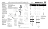
Figure 2-2: Wiring for Rosemount 56 and 1056 transmitters
Figure 2-3: Wiring for Rosemount 1066 transmitter
Quick Start Guide May 2019
8 Emerson.com/Rosemount

Figure 2-4: Wiring for Rosemount 5081 transmitters
2.2.1 Wiring through junction box
If wiring connections are made through a remote junction box (PN
23550-00), wire point-to-point. Use cable 23747-00 (factory-terminated) or
9200275 (no terminations).
May 2019 Quick Start Guide
Quick Start Guide 9

3 Calibrate
3.1 Cleaning the sensor
The Rosemount 404-17 (stainless steel body) sensor can be taken apart for
cleaning. However, in some cases, disassembling and reassembling the
sensor can cause the cell constant to change as much as 1%.
For maximum accuracy, the cell constant should be rechecked after the
sensor has been reassembled. The Rosemount 400-16 (PVC body) sensor
cannot be taken apart.
Use a warm detergent solution and a soft brush or pipe cleaner to remove oil
and scale. Isopropyl alcohol (rubbing alcohol) can also be used to remove
oily films. Avoid using strong mineral acids to clean conductivity sensors.
3.2 Calibrating the sensor
Rosemount 404 contacting conductivity sensors are calibrated at the factory
and do not need calibration when first placed in service.
Simply, enter the cell constant printed on the label into the transmitter.
After a period of service, the sensor may require calibration. Because
Rosemount 404 sensors have a flow-through design, they are best calibrated
against a referee meter and sensor where the two sensors are connected in
series with the same liquid flowing through both.
For more information about calibrating contacting conductivity sensors,
refer to application sheet ADS 43-024.
Quick Start Guide May 2019
10 Emerson.com/Rosemount

4 Maintaining and troubleshooting
4.1 Troubleshooting
Table 4-1: Rosemount 404 contacting conductivity sensor
troubleshooting
Problem Probable Cause Solution
Off-scale reading Wiring is wrong. Verify wiring.
Temperature element is
open or shorted.
Check temperature
element for open or short
circuits. See Figure 4-1.
Sensor is not in process
stream.
Be sure sensor is
completely submerged in
process stream.
Variopol cable is not
properly seated.
Loosen connector and
reseat.
Sensor has failed. Perform isolation checks.
See Figure 4-2.
Noisy reading Sensor is improperly
installed in process
stream.
Be sure sensor is
completely submerged in
process stream.
Variopol cable is not
properly seated.
Loosen connector and
reseat.
Reading seems wrong
(lower or higher than
expected)
Bubbles trapped in sensor. Be sure sensor is properly
oriented in pipe or flow
cell. See Figure 2-1. Apply
back pressure to flow cell.
Wrong temperature
correction algorithm.
Check that temperature
correction is appropriate
for the sample. See
transmitter manual for
more information.
Wrong cell constant. Verify that the correct cell
constant has been entered
in the analyzer and that
the cell constant is
appropriate for the
conductivity of the
sample. See transmitter
manual.
Sluggish response Electrodes are fouled. Clean electrodes.
May 2019 Quick Start Guide
Quick Start Guide 11

Table 4-1: Rosemount 404 contacting conductivity sensor
troubleshooting (continued)
Problem Probable Cause Solution
Sensor is sampling a dead
area.
Move sample line to a
location more
representative of the
process liquid.
Table 4-2: Measured resistance and temperature
Temperature Resistance
Pt 100 Pt 1000
0 °C 100.0 Ω
1000 Ω
10 °C 103.9 Ω 1039 Ω
20 °C 107.8 Ω 1078 Ω
30 °C 111.7 Ω 1117 Ω
40 °C 115.5 Ω 1155 Ω
50 °C 119.4 Ω 1194 Ω
Figure 4-1: Checking temperature element
Disconnect leads and measured resistance as shown in Figure 4-1.
The measured resistance should be close to the value shown in Table 4-2.
Quick Start Guide May 2019
12 Emerson.com/Rosemount


5 Accessories
Table 5-1: Rosemount 404 contacting conductivity sensor accessories
information
Part number Description
23550-00 Remote junction box without preamplifier
23747-00 Interconnect cable, prepped (must specify length)
9200275 Extension cable, unprepped (must specify length)
05010781899 Conductivity standard SS-6, 200 μS/cm, 32 oz (0.95 L)
05010797875 Conductivity standard SS-6A, 200 μS/cm, 1 gal (3.78 L)
05010782468 Conductivity standard SS-5, 100k0 μS/cm, 32 oz (0.95 L)
05010783002 Conductivity standard SS-5A, 1000 μS/cm, 1 gal (3.78 L)
05000705464 Conductivity standard SS-1, 1409 μS/cm, 32 oz (0.95 L)
05000709672 Conductivity standard SS-1A, 1409 μS/cm, 1 gal (3.78 L)
9210004 Conductivity standard, 2000 μS/cm, 16 oz
Quick Start Guide May 2019
14 Emerson.com/Rosemount

May 2019 Quick Start Guide
Quick Start Guide 15

*00825-0100-3404*
Quick Start Guide
00825-0100-3404, Rev. AA
May 2019
GLOBAL HEADQUARTERS
Emerson Automation Solutions
6021 Innovation Blvd
Shakopee, MN 55379, USA
+1 800 999 9307 or +1 952 906 8888
F +1 952 949 7001
NORTH AMERICA
Emerson Automation Solutions
8200 Market Blvd
Chanhassen, MN 55317
Toll Free +1 800 999 9307
F +1 952 949 7001
EUROPE
Emerson Automation Solutions
Neuhofstrasse 19a P.O. Box 1046
CH-6340 Baar
Switzerland
T + 41 (0) 41 768 6111
F + 41 (0) 41 768 6300
MIDDLE EAST AND AFRICA
Emerson Automation Solutions
Emerson FZE
Jebel Ali Free Zone
Dubai, United Arab Emirates, P.O. Box
17033
T +971 4 811 8100
F +971 4 886 5465
Linkedin.com/company/Emerson-
Automation-Solutions
twitter.com/rosemount_news
Facebook.com/Rosemount
youtube.com/RosemountMeasurement
©
2019 Emerson. All rights reserved.
The Emerson logo is a trademark and service
mark of Emerson Electric Co. Rosemount is a
mark of one of the Emerson Process
Management family of companies. All other
marks are the property of their respective
owners. The contents of this publication are
presented for information purposes only, and,
while effort has been made to ensure their
accuracy, they are not to be construed as
warranties or guarantees, express or implied,
regarding the products or services described
herein or their use or applicability. All sales are
governed by our terms and conditions, which are
available on request. We reserve the right to
modify or improve the designs or specifications
of our products at any time without notice.
/