Page is loading ...

BA43E000
Operating Instructions
ERHARD NON SLAM
Nozzle Check Valve
ERHARD NON SLAM
Nozzle Check Valve
ERHARD NON SLAM
Nozzle Check Valve (option)
You are requested to follow operating
instructions BA43D001.
BA43E000
Juli 2009
Rev.9
ERHARD GmbH & Co. KG x D-89502 Heidenheim x Postfach 1280
Telefon: (07321) 320-0
(07321) 320 491 E-Mail: info@erhard.de
Internet: http://www.erhard.de
Page 1 of 18

Operating Instructions for ERHARD NON SLAM Nozzle Check Valve
BA43E000
Juli 2009
Rev.9
ERHARD GmbH & Co. KG x D-89502 Heidenheim x Postfach 1280
Telefon: (07321) 320-0
(07321) 320 491 E-Mail: info@erhard.de
Internet: htt
p
://www.erhard.de
Page 2 of 18
Index of contents
These operating instructions must always be used in combination with operating
instructions BA01E001!
1. Description of product and performance 3
1.1 ERHARD NON SLAM Nozzle Check Valves 5
DN 80 - 600, PN 10 – PN 40 prod. No. 435...00
1.2 Design Features – Technical Data 5
1.2.1 ERHARD NON SLAM Nozzle Check Valves
DN 80 – 300 1.2.2 5
1.2.2 ERHARD NON SLAM Nozzle Check Valves
DN 350 – 600 7
1.3 Performance and mode of operation 8
1.4 Application according to the rules 9
1.5 Transport and storage 9
1.5.1 Transport 9
1.5.2 Storage 10
1.6 Installation into the pipeline 10
2. Maintenance 14
2.1 Maintenance 15
2.2 Spare parts 15
2.3 Replacement of spare parts / necessary devices 16
2.4 Trouble during operation and remedies 18

Operating Instructions for ERHARD NON SLAM Nozzle Check Valve
1 Description of Product and Performance
ERHARD NON SLAM Nozzle Check Valves (EDRV)
DN 80 – 600, PN10 – PN40 Product No. 435...00
The ERHARD NON SLAM Nozzle Check Valve is a non-return valve of compact design
and short pattern, with central rubber-coated valve disc (DN 80-300) or valve ring (DN
350-600) which opens and closes in axial direction, the closing movement being spring-
assisted.
Thanks to the materials and the sealing and corrosion protection systems, the
ERHARD NON SLAM Nozzle Check Valve is suitable for application in the water
industry (mechanically neutral water up to a max. temperature of 60° C) and for pre-
treated sewage.
In case of hot flow media, there is the risk of burns and the valve has to be heat-
insulated by the user.
The normal range of flow velocity of the ERHARD NON SLAM Nozzle Check Valve is
0,5 – 5 m/s (referred to the nominal size DN). At a velocity of 2 m/s (referred to DN) the
ERHARD NON SLAM Nozzle Check Valve is used in a fully economical way. With
these velocities, all nominal sizes are in fully open position.
For opening the ERHARD NON SLAM Nozzle Check Valve , according to DN, 0,5 – 0,9
mWC (50 – 90 mbar) as minimum differential pressure is necessary. The valve opens at
this differential pressure and the medium begins to flow. For tight closure, a minimum
back pressure of approx. 4.0 mWC (400 mbar) is necessary for DN 80 – 300 and of
approx. 8 mWC (800 mbar) for DN 350 – 600.
BA43E000
Juli 2009
Rev.9
ERHARD GmbH & Co. KG x D-89502 Heidenheim x Postfach 1280
Telefon: (07321) 320-0
(07321) 320 491 E-Mail: info@erhard.de
Internet: htt
p
://www.erhard.de
Page 3 of 18

Operating Instructions for ERHARD NON SLAM Nozzle Check Valve
Pressures:
Nominal size
PN PFA PMA PEA
DN [bar] [bar] [bar]
body seat
80 - 300
350 - 600
80 - 300
350 - 600
80 - 300 25 25 30 35 37,5 25
80 - 300 40 40 48 56 60 40
24 1616 16 20 25
H
y
dr. test
p
ressure
[
bar
]
fo
r
10 10 12 17 15 10
The ERHARD NON SLAM Nozzle Check Valves are tested at the manufacturers' works
for strength and tightness according to DIN EN 12266 / 1074.
BA43E000
Juli 2009
Rev.9
ERHARD GmbH & Co. KG x D-89502 Heidenheim x Postfach 1280
Telefon: (07321) 320-0
(07321) 320 491 E-Mail: info@erhard.de
Internet: htt
p
://www.erhard.de
Page 4 of 18

Operating Instructions for ERHARD NON SLAM Nozzle Check Valve
1.2 Design Features – Technical Data
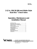
1.2.1 ERHARD NON SLAM Nozzle Check Valve DN 80 – 300
Fig. 1.1
Dimensions of ERHARD NON SLAM Nozzle Check Valve DN 80 – 300:
øz øz øz øz
80
200 160 132 200 160 132 200 160 19 132 200 160 19 132 3 180
100
220 180 156 220 180 156 235 190 23 156 235 190 23 156 3 190
125
250 210 184 250 210 184 270 220 184 23,5 270 220 184 23,5 3 200
150
285 240 211 285 240 211 300 250 211 26 300 250 211 26 3 210 -
200
340 295 266 20 340 295 266 20 360 310 274 22 375 320 31 284 30 3 230 -
250
400 350 319 22 400 355 319 22 425 370 330 24,5 450 385 345 34,5 3 250 -
300
455 400 370 24,5 455 410 370 24,5 485 430 16 389
27,5
515 450 16 409 39,5 4 270 20
DN
23
PN10 PN16
12
Døk d4b
28
PN40
d2 d2 d2 d2
d4 b D øk D øk D økd4 b
12
34
12
12
31
19
f
8
19
19
23
819
28
8
19
28
8
19
d4 b L l*
PN25
*Attention: For nominal size DN 300 the guiding stem protrudes by 20 mm
when the valve disc is open!
BA43E000
Juli 2009
Rev.9
ERHARD GmbH & Co. KG x D-89502 Heidenheim x Postfach 1280
Telefon: (07321) 320-0
(07321) 320 491 E-Mail: info@erhard.de
Internet: htt
p
://www.erhard.de
Page 5 of 18

Operating Instructions for ERHARD NON SLAM Nozzle Check Valve
Parts list for ERHARD NON SLAM Nozzle Check Valves DN 80 – 300
with standard materials
Item
Description Qty. Notes
PN10/16 PN25/40
Body 80-125
Body 150 - 300 EN-JS1030 EN-JS1025
2 Internal body 1 zinc-free bronze
3 Threaded pin 3 stainless steel
4Bush 2
5,8,9 Valve disc 1
vulcanized NBR or EPDM
rubber-coating
6 Guiding stem 1 stainless steel
7 Pressure spring 1
Material / Standard
ductile cast iron11
EN-JS1025
2.1050.01
2.1050.01/NBR or
2.1050.01/EPDM
1.4057.05
1.4310
A4
High-performance polymer
BA43E000
Juli 2009
Rev.9
ERHARD GmbH & Co. KG x D-89502 Heidenheim x Postfach 1280
Telefon: (07321) 320-0
(07321) 320 491 E-Mail: info@erhard.de
Internet: htt
p
://www.erhard.de
Page 6 of 18

Operating Instructions for ERHARD NON SLAM Nozzle Check Valve
1.2.2 ERHARD NON SLAM Nozzle Check Valves DN 350 – 600
Fig. 1.2
Dimensions of ERHARD NON SLAM Nozzle Check Valve DN 350 – 600:
øz øz
350
505 460 23 429 26,5 520 470 28 429 26,5 290 8
400
565 515 480 28 580 525 31 480 28 310 10
500
670 620 582 31,5 715 650 34 609 31,5 350 15
600
780 725 31 682 30 840 770 37 720 36 5 390 9
4
f
28
16
20
16
20
bDøk
DN
PN10 PN16
Døk d4b
d2 d2
d4 L l*
*Attention: DN 350 – 600: the guiding stems protrude over the face-to-face dimension when the valve ring
is open!
BA43E000
Juli 2009
Rev.9
ERHARD GmbH & Co. KG x D-89502 Heidenheim x Postfach 1280
Telefon: (07321) 320-0
(07321) 320 491 E-Mail: info@erhard.de
Internet: htt
p
://www.erhard.de
Page 7 of 18

Operating Instructions for ERHARD NON SLAM Nozzle Check Valve
Parts list for ERHARD NON SLAM Nozzle Check Valves DN 350 – 600
with standard materials
Item Description Qty. Material Notes
Body 350 - 400 EN-JS1030
Body 500 - 600 EN-JS1025
2 Internal body 1 2.1050.01 zinc-free bronze
3 Threaded pin 4 A4 stainless steel
4 Bush 8 High-performance polymer
5 Piston ring 1 1.4404/EPDM
vulcanised EPDM rubber-
coating
6 Guide rod 4 1.4057.05 stainless steel
7 Pressure spring 4 1.4310.07 stainless steel
8 Threaded bush 4 A4 stainless steel
9 Washer 4 NBR or EPDM
10 Cover 1 2.1050.01 zinc-free bronze
ductile cast iron11
Corrosion protection for DN 80 – 600:
The body is internally vitreous-enamelled and externally EKB coated (synthetic epoxy
coating). All other parts are made of stainless materials.
Recesses are provided at the centering of the internal body in the main body so that the
transitions between the uncoated and coated surface can be filled with sealing agent.
This protects and seals these critical areas against the flow medium.
1.3 Performance and Mode of Operation
The ERHARD NON SLAM Nozzle Check Valve is a flow-controlled non-return valve
with centrally and axially moved obturator. This obturator with the shape of a valve disc
(DN 80 – 300) or a valve ring (for DN 350 and larger) is guided by means of one (four) a
guiding stem(s) in an internal body. The closing movement of the valve is spring-
assisted (one or four springs).
The ERHARD NON SLAM Nozzle Check Valve is resilient-seated, with tight closure
according to DIN EN 12266 / 1074 – leakage rate 1 (0 drop per minute), at a minimum
back pressure of 4.0 mWC (400 mbar) and larger for DN 80 – 300 and a minimum back
pressure of 8.0 mWC (800 mbar) and larger for DN 350 – 600.
The valve starts opening at incipient velocity and is fully open at a velocity of approx. 2
m/s. The opening process can be influenced by a special spring which is designed for
special cases of application.
The standard design is suitable for installation in horizontal pipeline and for vertical
pipeline and for vertical upward flow. When the valve is installed in a vertical pipeline
with downward flow, the ERHARD NON SLAM Nozzle Check Valve has to be equipped
with a special spring. Moreover, a remachined internal body is used which is designed
with additional bores for drainage of the internal body (see fig. 1.1 and 1.2).
BA43E000
Juli 2009
Rev.9
ERHARD GmbH & Co. KG x D-89502 Heidenheim x Postfach 1280
Telefon: (07321) 320-0
(07321) 320 491 E-Mail: info@erhard.de
Internet: htt
p
://www.erhard.de
Page 8 of 18

Operating Instructions for ERHARD NON SLAM Nozzle Check Valve
1.4 Application according to the rules
Thanks to their design, the ERHARD NON SLAM Nozzle Check Valves are applied
according to the General Instructions BA01E001 Section 1.1.
1.5 Transport and storage
1.5.1 Transport
It is not allowed to attach the lifting gears in the flange holes or to roll the valve on the
outside diameter of the flanges which would damage the corrosion protection.
Weights of the ERHARD NON SLAM Nozzle Check Valves:
DN 80 100 125 150 200 250 300 350 400 500 600
PN
10
----50,070,0100,0 130,0 160,0 260,0 420,0
16
14,0 19,0 27,0 32,5 50,0 70,0 100,0 135,0 165,0 275,0 480,0
25
14,0 19,0 27,0 40,0 56,5 81,5 113,0 - - - -
40
14,0 19,0 27,0 40,0 67,5 101,0 145,5 - - - -
Weight approx.
in kg
The ERHARD NON SLAM Nozzle Check Valves DN 300 and smaller should be
transported by means of belts which are to be placed around the flange necks and to
be suspended at the lifting gear (see fig. 1.3).
The ERHARD NON SLAM Nozzle Check Valves DN 350 to 600 are provided with
threaded holes (M16) at the flanges. Thus, it is possible to transport the ERHARD
Check Valves by means of eyebolts.
BA43E000
Juli 2009
Rev.9
ERHARD GmbH & Co. KG x D-89502 Heidenheim x Postfach 1280
Telefon: (07321) 320-0
(07321) 320 491 E-Mail: info@erhard.de
Internet: htt
p
://www.erhard.de
Page 9 of 18

Operating Instructions for ERHARD NON SLAM Nozzle Check Valve
Fig. 1.3: Installation in horizontal pipeline
(left hand: Check Valve DN 80 – 300, right
hand: Check Valve DN 350 – 600)
Fig. 4.2: Installation in vertical
pipeline
For installation into vertical pipeline insert two bolts of appropriate material and strength
into two opposite flange holes to which the belts are fixed at the flange back (see fig.
1.4). Please provide protective devices at the bolts (e.g. sleeves of plastic material ...)
for protecting the coating of the flange holes.
1.5.2 Storage
The ERHARD NON SLAM Nozzle Check Valves are to be secured by means of wedges
or belts (fig 1.5) against rolling off, or good stability has to be ensured by putting them
horizontally on the flange (fig. 1.6).
Fig. 1.5 Fig.1.6
1.6 Installation into the Pipeline
Remove all packing material from the valve. Prior to installation, check the pipeline
for impurities and foreign bodies and clean it if necessary.
BA43E000
Juli 2009
Rev.9
ERHARD GmbH & Co. KG x D-89502 Heidenheim x Postfach 1280
Telefon: (07321) 320-0
(07321) 320 491 E-Mail: info@erhard.de
Internet: htt
p
://www.erhard.de
Page 10 of 18

Operating Instructions for ERHARD NON SLAM Nozzle Check Valve
Attention !
Follow direction of installation
according to the cast-on arrow!
The valve opens in case of flow from A to
B and closes in reverse direction from B to
A, thus preventing backflow!
Fig. 1.7
There must be free access all around the valve for operation and maintenance.
Prior to installation into the pipeline the function of the ERHARD NON SLAM Nozzle
Check Valve can be checked by pressing the obturator onto the stop of the internal
body. When releasing the obturator, the obturator must be pressed into the seat by the
spring, completely and automatically. (Check installation position accordingly.)
Fig. 5.2 Standard nameplate
Installation in horizontal and vertical pipeline is
possible. For installation in vertical pipeline with
upward flow a standard spring is used as for
installation in horizontal pipeline. The installation
position is marked on the nameplate (5.2). The
springs for the standard case (→ ↑) are marked
accordingly – like all the other springs.
A special spring is used for installation in vertical
pipeline with downward flow (↓). In this case, the
internal body has an additional bore.
ERHARD NON SLAM Nozzle
Check Valve
Serial No.: 000000/00/00
Admiss.work.pressure PFA __bar
Flanges PN ??
Sealing material: NBR
Spring: standard
Position of installation: →↑
During installation of the valve, the distance between the pipe flanges should exceed
the valve face-to-face dimension by at least 20 mm. Thus, the raised faces will not be
damaged and the gaskets can be inserted. Up to PN 16 textile reinforced rubber seals
are recommended for use as flange gaskets. Steel-reinforced rubber seals are
recommended for PN 25 and higher. For slip-on flanges, they are absolutely
necessary. (Consider resistance to flow medium and temperature.)
The mating pipe flanges must be plain-parallel and concentric.
Tighten the connecting bolts evenly (without distortion) and crosswise. The pipeline
mustn't by any means be pulled up to the valve.
BA43E000
Juli 2009
Rev.9
ERHARD GmbH & Co. KG x D-89502 Heidenheim x Postfach 1280
Telefon: (07321) 320-0
(07321) 320 491 E-Mail: info@erhard.de
Internet: htt
p
://www.erhard.de
Page 11 of 18

Operating Instructions for ERHARD NON SLAM Nozzle Check Valve
Warning
Warning
Follow the applicable safety rules according to
VGB 9a and wear the
necessary personal protective equipment.
Risk of injury!
Attention! Risk of bruises!
During transport or installation of the
ERHARD NON SLAM Nozzle Check
Valves, there may be the risk of
bruising the fingers by uncontrolled
movement of the obturator.
Risk of penetration of flow medium!
Prior to putting into operation and after carrying out maintenance work, check
tightness of the flange connections and screwed connections if any or replace the
seals.
Attention: For DN 300 – 600, the guiding stems exceed the face-to-face
dimension of the valve in fully open position (see Tables
"Dimensions of ERHARD NON SLAM Nozzle Check Valves DN 80 -
300" and "Dimensions of ERHARD NON SLAM Nozzle Check Valves
350 – 600". Consider corresponding valves or fittings downstream of
the valve!
Installation directly upstream or downstream of bends, T-pieces or valves has
to be avoided.
BA43E000
Juli 2009
Rev.9
ERHARD GmbH & Co. KG x D-89502 Heidenheim x Postfach 1280
Telefon: (07321) 320-0
(07321) 320 491 E-Mail: info@erhard.de
Internet: htt
p
://www.erhard.de
Page 12 of 18

Operating Instructions for ERHARD NON SLAM Nozzle Check Valve
Note concerning installation:
Fig. 1.9
We recommend to design the non-return
valve in the nominal size DN of the
delivery side of the pump. (DN of pump =
DN of ERHARD NON SLAM Nozzle
Check Valve.)
Thus, there will be – referred to the
nominal size – a higher flow velocity and
thus an optimum operating performance
(opening degree, economic efficiency). If
the ERHARD NON SLAM Nozzle Check
Valve is mounted directly on the delivery
side of the pump, irregular flow and
vibrations of the ERHARD Check Valve
might have negative effects (releasing
screwed connections, damaging the
seals, spring breaking, and increased
wear and tear of the mobile valve and
bearing components).
Therefore we recommend a distance of
min. 5 – 7 x DN (especially for speed-
controlled pumps) or a minimum velocity
of 2 – 3 m/s for the ERHARD NON SLAM
Nozzle Check Valve in order to ensure
that the valve is fully open.
BA43E000
Juli 2009
Rev.9
ERHARD GmbH & Co. KG x D-89502 Heidenheim x Postfach 1280
Telefon: (07321) 320-0
(07321) 320 491 E-Mail: info@erhard.de
Internet: htt
p
://www.erhard.de
Page 13 of 18

Operating Instructions for ERHARD NON SLAM Nozzle Check Valve
2 Maintenance
Control of the performance and tightness of the ERHARD NON SLAM Nozzle Check
Valve is to be done at regular intervals according to DVGW print W390. Inspection or
repair of the valve must not be carried out before the pipe section in which the valve is
installed has been isolated and made pressure-less.
Warning
WARNING
Before carrying out maintenance work on the
valve, any pressurised pipeline has to be
made pressure-less and to be secured
against re-starting!
After finishing the maintenance work, any
connection has to be checked for tightness
and close fit.
Danger
DANGER
In case of penetration of dangerous liquids, substances, gases, and
steams, immediately the plant has to be shut down, the responsible
supervisor must be informed and appropriate repair work has to be
carried out.
The personal protective equipment according to the rules of the
employer's liability insurance association must be used. Depending
on the flow medium, there is the risk of poisoning, causticization,
scalding, and danger due to biological and microbiological
substances as well as the risk of fire and explosion!
BA43E000
Juli 2009
Rev.9
ERHARD GmbH & Co. KG x D-89502 Heidenheim x Postfach 1280
Telefon: (07321) 320-0
(07321) 320 491 E-Mail: info@erhard.de
Internet: htt
p
://www.erhard.de
Page 14 of 18

Operating Instructions for ERHARD NON SLAM Nozzle Check Valve
2.1 Maintenance
ERHARD NON SLAM Nozzle Check Valves are maintenance-free.
Recommended intervals for inspection and maintenance:
Continuous 2 x per year Yearly
ERHARD NON SLAM Nozzle Check
Valve installed in plants
• performance test (Open – Closed)
• tightness test
• head loss measurement
♦
♦
♦
Other checks
• external leakage
• damages
• contamination / ease of operation
• noise
♦
♦
♦
♦
2.2 Spare parts
When spare parts are required, it is necessary to specifiy the serial number of the valve.
The serial number is specified on the name plate (fig. 1.8). All data required for
selecting the appropriate spare parts are assigned to the serial number.
For 2 and 5 years‘operation wearing parts are not necessary.
The following spare parts for the ERHARD NON SLAM Nozzle Check Valve are defined
as wearing parts:
ERHARD NON SLAM Nozzle Check Valves DN 80 – 300:
1. Completely mounted unit (if necessary):
rubber-coated valve disc (1) with
guiding stem (2) and washer (5).
2. Spring (3)
(if necessary)
3. Bush (4) 2 pieces
Fig. 2.1
BA43E000
Juli 2009
Rev.9
ERHARD GmbH & Co. KG x D-89502 Heidenheim x Postfach 1280
Telefon: (07321) 320-0
(07321) 320 491 E-Mail: info@erhard.de
Internet: htt
p
://www.erhard.de
Page 15 of 18

Operating Instructions for ERHARD NON SLAM Nozzle Check Valve
ERHARD NON SLAM Nozzle Check Valves DN 350 - 600:
1. Completely mounted unit (if
necessary): rubber-coated valve
ring (1) with 4 guiding stems (2) and
washers (5).
2. Springs (3)
(if necessary) 4 pieces
4. Bushes (4) 4 or 8 pieces
Fig. 2.2
2.3 Replacement of the spare parts / necessary tools
For replacing above mentioned wearing parts, the ERHARD NON SLAM Nozzle Check
Valve has to be removed from the pipeline after having depressurized the pipeline. The
internal body (2) is secured in the body (3) in the following manner:
- for sizes DN 80 to 300 with 3 threaded pins M6 with internal hexagon 3 mm (1),
- for sizes DN 350 to 500 with 4 threaded pins M6 with internal hexagon 3 mm (1) and
- for size DN 600 with 4 threaded pins M8 with internal hexagon 4 mm.
These pins must be screwed off.
Fig. 2.3.1
DN 80 – 300:
For removing the internal body (2) from
the body (3), a force of approx. 20 kN
is required. This force can be applied
by means of a press, an auxiliary
mounting tool or similar device as
shown in fig. 2.3.1.
The tool is centrally placed on the
pushed back valve disc, both bolts are
tightened in two opposite flange holes
with washers and nuts, parallel to the
raised face. The internal body is
pressed out of the main body by means
of the central bolt (4). When pressing
the internal body out of its position, it
should be held in order to avoid
damage to the coating.
BA43E000
Juli 2009
Rev.9
ERHARD GmbH & Co. KG x D-89502 Heidenheim x Postfach 1280
Telefon: (07321) 320-0
(07321) 320 491 E-Mail: info@erhard.de
Internet: htt
p
://www.erhard.de
Page 16 of 18

Operating Instructions for ERHARD NON SLAM Nozzle Check Valve
Fig. 2.3.2
DN 350 – 600:
For removing the internal body (2) from
the body (3), a force of approx. 40 kN
is required. This force can be applied
by means of a press, an auxiliary
mounting tool or similar device as
shown in fig. 2.3.2.
The tool is centrally placed on the
pushed back valve ring so that the
bolts (4) required for expulsion are
centrally arranged on the width of the
valve ring. The two fastening bolts are
tightened in two opposite flange holes
with washers and nuts, parallel to the
raised face.
The internal body is pressed out of the
main body, screwing-in the bolts (4) in a
slow and uniform manner. When
screwing-in, the corresponding nuts
have
to be secured against following the
bolts. When pressing the internal
body out of its position, it should be
held
in order to avoid damage to the coating.
Assembly DN 80 – 600:
During assembly, internal body, valve disc (ring), spring(s), and guiding stem(s) are
pushed into the internal body. The valve disc (ring) can be fixed in its rear limit position
by means of bolt(s) including washer(s) (5), screwed into the guiding stem(s). The fitting
surface (fig. 2.4) of the internal body, has to be cleaned. The body’s fitting surface which
must also be cleaned has to be covered with sealing agent BA5
1
on the two transitions
to vitreous enamel as well as in the groove in which the threaded pins are engaged.
After having pushed the internal body into the main body, the threaded pins have to be
secured with BA5, too, and screwed into the groove. The internal hexagon of the
threaded pins is filled with BA5 in order to ensure further screwing off. Excessive
sealing agent must be removed from both transitions and be smoothed. For mounting
the internal body in the main body, see also fig. 2.4.
1
Sealing agent BA5 Loctite Deutschland GmbH Type: screw locking, medium strength
Art.-No. 24374
BA43E000
Juli 2009
Rev.9
ERHARD GmbH & Co. KG x D-89502 Heidenheim x Postfach 1280
Telefon: (07321) 320-0
(07321) 320 491 E-Mail: info@erhard.de
Internet: htt
p
://www.erhard.de
Page 17 of 18

Operating Instructions for ERHARD NON SLAM Nozzle Check Valve
Fig. 2.4:
Curing of the sealing agent takes about 5 hours.
2.4 Troubles during operation of the ERHARD NON SLAM Nozzle Check Valve
and remedies
Trouble Possible Causes Remedy
Deposits or dirt in the seating zone In case of firm incrustations, clean
seating zone and valve disc/ring
Leakage in the seat
Damage to the coating of the valve
disc/ring
Replace valve disc/ring, see
paragraph 2.3
Clogging and seizing of the spring Clean spring, in case of very dirty
medium: provide spring protecting
device, for dismantling see
paragraph 2.3
Deposits on guiding stem Open valve manually several times
until valve can be operated easily
again or dismantle according to
paragraph 2.3 and clean guiding
stem and bore
High head loss
Foreign bodies between valve
disc/ring and internal body
Manually remove foreign body,
dismantling acc. to 2.3
Foreign bodies jammed in the
seating zone at v (referred to DN)
<2 m/s
Increase flow velocity and flush out
foreign bodies
Valve blocked
Foreign bodies jammed in the
seating zone at v (referred to DN)
>2 m/s
Manually remove foreign bodies
Return spring broken
Replacement of spring, see
paragraph 2.3
Increased noise
(closing shocks)
Deposits in the guiding device due
to low flow velocity
Cleaning of the bore.
For dismantling, see paragraph
2.3.
Valves installed in a
wrong way,
contrary to the specified
direction of installation
Pump discharges against closed
valve.
The direction arrow has not been
followed during installation.
Removal of the valve from the
pipeline
Installation into the pipeline, see
1.6.
BA43E000
Juli 2009
Rev.9
ERHARD GmbH & Co. KG x D-89502 Heidenheim x Postfach 1280
Telefon: (07321) 320-0
(07321) 320 491 E-Mail: info@erhard.de
Internet: htt
p
://www.erhard.de
Page 18 of 18
/