Page is loading ...

BCMS Vu Wallboard Models WB1,
WB2, WB3, IW1, IW2, and IW3
Installation, Programming, and
Troubleshooting
555-233-108
Comcode 108395153
Issue 1
November 1998

Copyright
1998, Lucent Technologies
All Rights Reserved
Printed in USA
Notice
Every effort was made to ensure that the information in this book was complete and
accurate at the time of printing. However, information is subject to change.
Your Responsibility for Your System’s Security
Toll fraud is the unauthorized use of your telecommunications system by an
unauthorized party, for example, persons other than your company’s employees,
agents, subcontractors, or persons working on your company’s behalf. Note that there
may be a risk of toll fraud associated with your telecommunications system and, if toll
fraud occurs, it can result in substantial additional charges for your
telecommunications services.
You and your system manager are responsible for the security of your system, such as
programming and configuring your equipment to prevent unauthorized use. The
system manager is also responsible for reading all installation, instruction, and system
administration documents provided with this product in order to fully understand the
features that can introduce risk of toll fraud and the steps that can be taken to reduce
that risk. Lucent Technologies does not warrant that this product is immune from or
will prevent unauthorized use of common-carrier telecommunication services or
facilities accessed through or connected to it. Lucent Technologies will not be
responsible for any charges that result from such unauthorized use.
Lucent Technologies Fraud Intervention
If you suspect that you are being victimized by toll fraud and you need technical
support or assistance, call Technical Service Center Toll Fraud Intervention Hotline at
1 800 643-2353.
Federal Communication Commission (FCC) Statement
This equipment has been tested and found to comply with the limits for a Class A
digital device, pursuant to Part 15 of the FCC Rules. These limits are designed to
provide reasonable protection against harmful interference when the equipment is
operated in a commercial environment. This equipment generates, uses, and can
radiate radio frequency energy and, if not installed and used in accordance with the
instruction manual, may cause harmful interference to radio communications.
However, there is no guarantee that interference will not occur in a particular
installation. For further FCC information, see “Customer Support Information” below.
Trademarks
BCMS Vu is a trademark of Lucent Technologies.

Ordering Information
Call: Lucent Technologies Publications Center
Voice 1 800 457-1235 International Voice 317 322-6416
Fax 1 800 457-1764 International Fax 317 322-6699
Write: Lucent Technologies Publications Center
2855 N. Franklin Road
Indianapolis, IN 46219
Order: Document No. 555-233-108
Comcode 108395153
Issue 1, November 1998
Support Telephone Number
In the continental US, Lucent Technologies provides a toll-free customer helpline 24
hours a day. Call the Lucent Technologies Helpline at 1 800 242-2121 or your Lucent
Technologies authorized dealer if you need assistance when installing, programming, or
using your system. Outside the continental US, contact your local Lucent Technologies
representative.
Warranty
Lucent Technologies, Inc. warrants this equipment to be free of defects in materials
and workmanship for a period of one year from date of shipment. All defects within
this time will be repaired without charge upon return of the unit to the factory.
This warranty is null and void if the manufacturer determines that any modifications
have been made to the unit or the unit has been subjected to physical or electrical
stress.
This warranty covers parts and labor only and does not include shipping costs, travel
expenses, or travel time.
Installation of the equipment is the sole responsibility of the purchaser. The
manufacturer, its agents, or its distributors accept no responsibility for malfunction or
damage caused by improper treatment or connection of the unit.
The manufacturer, its agents, or its distributors are not liable for any losses incurred
through use or malfunction of the equipment or any losses or damages incurred by the
use of the equipment in any means whatsoever.
This warranty is limited to the repair of the equipment to its normal functioning
capability.
This warranty is complete as stated and all other warranties, expressed or implied, are
invalid. The BCMS Vu Wallboard Models should be installed only by qualified
personnel. No user-serviceable parts are contained within the units. Installation or
programming should not begin prior to review of all sections of this manual.

Issue 1 November 1998 i
Contents
■ BCMS Vu™ Wallboard..................................................1
■ Installation.....................................................................5
Installing the Wallboard..........................................5
Considerations .......................................5
Wall-Mounted Installation .......................6
Counter-Mounted Installation ...............10
Ceiling-Suspended Installation ............11
Installing the Converter Box.................................14
Required Parts .....................................15
Procedure ............................................16
The EOL Terminators ...........................19
■ Programming the Wallboard.......................................22
Running the Self-Test Program............................22
Clearing the Memory............................................23
■ EPROM Replacement.................................................23
■ Setting the Jumper .....................................................25
■ Troubleshooting..........................................................26
First Start-Up ........................................................26
Trouble After Installation ......................................29
Wallboard Problems.............................................31
Common Customer Questions.............................32
■ Parts List.....................................................................33

Issue 1 November 1998 ii
Figures
1) Mounting on a Wall . . . . . . . . . . . . . . . . . . . . . . . . . . . . . . . . .8
2) Mounting on a Counter . . . . . . . . . . . . . . . . . . . . . . . . . . . . .11
3) Suspending from a Ceiling . . . . . . . . . . . . . . . . . . . . . . . . . .13
4) Converter Box—Front View . . . . . . . . . . . . . . . . . . . . . . . . .15
5) Converter Box—Rear View . . . . . . . . . . . . . . . . . . . . . . . . . .17
6) RS-232 Pinouts . . . . . . . . . . . . . . . . . . . . . . . . . . . . . . . . . . .18
7) RS-485 Network Connection Using Modular Jacks . . . . . . .19
8) Converter Box on One End of Transmission . . . . . . . . . . . .20
9) Converter Box in Middle of Transmission . . . . . . . . . . . . . . .21
10) Replacing the EPROM . . . . . . . . . . . . . . . . . . . . . . . . . . . . .25
11) Setting the Jumper . . . . . . . . . . . . . . . . . . . . . . . . . . . . . . . .26


Issue 1 November 1998 v
Important Safety Instructions
When installing electrical equipment, always follow basic safety
precautions to reduce the risk of fire, electrical shock, and injury
to persons, including:
■ Read and understand all instructions.
■ Follow all warnings and instructions marked on or
packed with the product.
■ Never install this unit during a lightning storm.
■ Use only Lucent Technologies-recommended/approved
accessories.
■ Do not install this product near water, for example, in a
wet basement location.
■ Do not overload wall outlets, as this can result in the risk
of fire or electrical shock.
■ Do not attach the power supply cord to building
surfaces. Do not allow anything to rest on the power
cord. Do not locate this product where the cord will be
abused by persons walking on it.
■ Unplug the product from the wall outlet before cleaning.
Use a damp cloth for cleaning. Do not use cleaners or
aerosol cleaners.
■ Do not operate the system if chemical gas leakage is
suspected in the area. Use telephones located in some
other safe area to report the trouble.
SAVE THESE INSTRUCTIONS

Issue 1 November 1998 1
BCMS Vu™ Wallboard Models
WB1, WB2, WB3, IW1, IW2, and
IW3
Installation, Programming, and
Troubleshooting Instructions
BCMS Vu™ Wallboard
The BCMS Vu Wallboards are indoor light-emitting diode (LED)
message centers designed for use with the BCMS Vu software
package. BCMS Vu is a PC software package that collects and
stores Basic Call Call Management System (BCMS) data from a
communications system. The wallboards can display two lines
of 2.1-inch characters in any combination of red, green, and
amber.
NOTE:
The wallboards can be used only with BCMS Vu software.
See the documentation that came with the BCMS Vu
software.
The wallboards come in six models:
■ WB1 (PEC 5340-WB1) with a capacity of
40 typical characters in a two-line format
■ WB2 (PEC 5340-WB2) with a capacity of
52 typical characters in a two-line format

BCMS Vu™ Wallboard
2 Issue 1 November 1998
■ WB3 (PEC 5340-WB3) with a capacity of
64 typical characters in a two-line format
■ IW1 (PEC 5340-IW1) with a capacity of
40 typical characters in a two-line format
■ IW2 (PEC 5340-IW2) with a capacity of
52 typical characters in a two-line format
■ IW3 (PEC 5340-IW3) with a capacity of
64 typical characters in a two-line format
The WB models are for use in the US, Canada, and Mexico;
IW models are for use in countries other than the US, Canada, and
Mexico.
NOTE:
When the phrase “the wallboard” is used, it refers to all the
WB and IW models listed above. When information is specific
to one model of the wallboard, it is so indicated.
Multiple wallboards can be networked together and connected to a
personal computer to form a visual information system that can be
updated automatically. These wallboards are used in customer
service applications where the messages can include such
information as the number of customers in queue, the number of
available agents, and the average time for a call to be answered.

BCMS Vu™ Wallboard
Issue 1 November 1998 3
Tables 1 and 2 show the characteristics specific (Table 1) and
common (Table 2) to the WB1, WB2, WB3, IW1, IW2, and IW3
wallboards.
Table 1. Characteristics Specific to a Wallboard Model
Characteristic
WB1 and IW1
Wallboard
WB2 and IW2
Wallboard
WB3 and IW3
Wallboard
Case Dimensions
(Depth dimension
includes rear-
mounted power
supply.)
40.2” L x 5.1” D
x 7.7” H
(102.1 cm L x
12.9 cm D x
19.6 cm H)
52.2” L x 5.1” D
x 7.7” H
(132.5 cm L x
12.9 cm D x
19.6 cm H)
64.2” L x 5.1” D
x 7.7” H
(163cm L x
12.9cm D x
19.6cm H
Weight
of Wallboard
18.5 lbs.
(8.4 kg)
24.5 lbs.
(11.2 kg)
31 lbs.
(14 kg)
Display
Dimensions
36” L x 4.8” H
(91.4 cm L x
12.2 cm H)
48” L x 4.8” H
(121.9 cm L x
12.2 cm H)
60” L x 4.8” H
(152cm L x
12.2cm H
Display Array 120 x 16 160 x 16 200 x 16
Characters in
Two-Line Format
40-60 maximum
depending on
characters
52-80 maximum
depending on
characters
66-100 maximum
depending on
characters
Characters in
One-Line Format
10-15 maximum
depending on
characters
14-20 maximum
depending on
characters
18-25 maximum
depending on
characters
Display Memory 28,000
characters
27,500
characters
27,000
characters

BCMS Vu™ Wallboard
4 Issue 1 November 1998
Table 2. Common Characteristics of All Six Wallboard Models
Characteristic Description
Pixel Size (diameter) 0.2" (0.5 cm)
Pixel (LED) Color Each dot can be red, green, or amber;
three rainbow effects are also available.
Center-to-Center
Spacing (pitch)
0.3" (0.8 cm)
Character Size
Two-Line Format 2.1" (5.3 cm)
Memory Retention Typically one month
Real-Time Clock Day and time, 12- or 24-hour format;
maintains accurate time without power
for up to 30 days.
Serial Computer
Interface
RS-232 (TTL) and RS-485 (multi-drop
networking for up to 255 wallboards)
Operating Mode Hold
Power WB1, WB2, and WB3:
120 VAC ±10%; 100 watts
IW1, IW2, and IW3:
220–240 VAC; 100–150 watts;
50–60 Hz; all ±10%
Power Cord Length 10 feet (3 meters)
Keyboard
(ordered separately)
Handheld, Eurostyle, infrared remote
control
Format EZ Key II™
Operating Temperature 32° to 120° F (0° to 49° C)
(Continued on next page)

Installation
Issue 1 November 1998 5
Installation
The complete installation of the wallboard involves installing the
wallboard and the converter box that is part of the Master Kit.
Installing the Wallboard
The wallboard can be installed in any of the following ways:
■ Mounted on a wall
■ Mounted on a counter
■ Suspended from a ceiling
Considerations
Consider the following when installing the wallboard:
■ Do not use the wallboard outdoors.
■ Do not expose the wallboard to direct sunlight.
Humidity Range 0% to 95% non-condensing
Mounting Ceiling, wall, or counter
Case Material Extruded aluminum
Safety Meets ETL, UL, and CSA standards;
international model meets CE standards
Table 2. Common Characteristics of All Six Wallboard Models
—
Characteristic Description

Installation
6 Issue 1 November 1998
■ Select a mounting location that has adequate ventilation on
all sides of the wallboard to avoid overheating. The
maximum operating temperature is 120°F (49°C).
■ Make sure an electrical outlet is near the wallboard.
■ Any mounting hardware you supply (chains, wall anchors,
“S” hooks, etc.) must be able to support at least four times
the weight of the wallboard.
!
CAUTION:
Do not paint the wallboard to match your office decor. Painting
the wallboard voids the warranty.
!
SECURITY ALERT:
If the wallboard is displaying sensitive BCMS data, be sure to
locate it where only authorized personnel can see the
information.
Wall-Mounted Installation
The list of parts needed and the steps for mounting the wallboard
on a wall are explained below. Unless otherwise stated, the
wallboard includes the parts mentioned.
Required Parts
■ Wallboard
■ Four (4) pivot brackets
■ Eight (8) #8-32 X .375" screws
■ Eight (8) #8-32 lockwashers
■ Two (2) 5/16" 18 X .50" screws
■ Two (2) 5/16" 18 hex nuts


Installation
8 Issue 1 November 1998
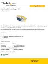
Figure 1. Mounting on a Wall
.280” diameter
Install one each on each end:
.187” diameter
5/16” x 0.50” screw
5/16” split lockwasher
5/16” hex nut
To adjust the viewing
angle, insert a cotter
pin into different holes
on each end
Rubber
Bumper
#8-32 x .375” screws
#8-32 lockwashers
WB2/IW2 46”
WB3/IW3 58”
WB1/IW1 34”

Installation
Issue 1 November 1998 9
3. Attach the large end of one pivot bracket to the desired
mounting surface by using two #8 screws.
!
CAUTION:
Do not install the wallboard directly to drywall or plasterboard.
Fasten it to wall studs or other structures that can support at
least 250 pounds.
4. Attach the second pivot bracket to the mounting surface at
the proper distance from the first bracket (varies depending
on wallboard model) by using two #8 screws.
NOTE:
Use the type of screws and anchoring method appropriate for
the mounting surface. For example, use wood screws if you
are mounting to a wood surface (these screws are not
supplied).
5. Mount two pivot brackets to the back of the wallboard with
eight #8-32 X .375" screws and eight #8-32 lockwashers.
Place the screws and lockwashers into the tapped holes on
the back of the wallboard that line up with the pivot bracket.
6. Line up the brackets on the back of the wallboard with the
pivot brackets you installed on the mounting surface. Insert a
5/16" X 0.50" screw through the larger holes of the lined-up
brackets, and place a split lockwasher and a 5/16" hex nut
on the end of the screw. Tighten until snug.
7. To adjust the viewing angle of the wallboard, insert a cotter
pin into one of the holes on the pivot bracket. Do the same
for the same-numbered hole on the other pivot bracket.

Installation
10 Issue 1 November 1998
Counter-Mounted Installation
The list of parts needed and the steps for mounting the wallboard
on a counter are explained below. Unless otherwise stated, the
wallboard includes the parts mentioned.
Required Parts
■ Wallboard
■ Four (4) pivot brackets
■ Eight (8) #8-32 X .375 screws
■ Eight (8) #8-32 lockwashers
■ Two (2) 5/16" 18 X .50 screws
■ Two (2) 5/16" 18 hex nuts
■ Two (2) 5/16" split lockwashers
■ Two (2) cotter pins
■ Eight (8) rubber bumpers
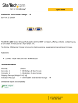
Procedure
Follow these steps to mount the wallboard on a counter
(see Figure 2):
1. As necessary, remove power from the wallboard.
2. Place two rubber bumpers on each pivot bracket.
3. Mount two pivot brackets to the back of the wallboard’s
aluminum extrusion by using four
#8-32 X .375" screws and four #8-32 lockwashers. Place the
screws with the lockwashers into the #8-32 tapped holes on
the extrusion that line up with the holes in the pivot bracket.
4. Screw the other sides of the pivot brackets into the counter.

Installation
Issue 1 November 1998 11
Figure 2. Mounting on a Counter
Ceiling-Suspended Installation
The list of parts needed and the steps for suspending the wallboard
from a ceiling are explained below. Unless otherwise stated, the
wallboard includes the parts mentioned.
Pivot Bracket
Rubber Bumper
(2) #8-32 x .375” screws
(2) #8-32 x lockwashers
.187” diameter holes
for counter mounting
(2 places)

Installation
12 Issue 1 November 1998
Required Parts
■ Wallboard
■ Two (2) hanging brackets
■ Two (2) #6-32 X .50" panhead screws
■ Two (2) #6-32 lockwashers
■ Two (2) “S” hooks
■ Chain for suspending the wallboard (not supplied with the
wallboard)
Procedure
Follow these steps to suspend a wallboard from the ceiling
(see Figure 3):
1. As necessary, remove power from the wallboard.
2. Remove an end cap from the wallboard.
3. Slide the two hanging brackets into the channel on the top of
the wallboard, and place the brackets at the appropriate
location.
4. Thread the #6-32 X .50" panhead screw into the hanging
bracket, and tighten until the screw engages the aluminum
extrusion.
5. Insert the “S” hooks into the holes in the hanging brackets.
To adjust the viewing angle, insert each “S” hook into
another hole in the bracket.
/