Page is loading ...

Congratulations and thanks for your purchase of the CODA Expert Disc Brake system. The CODA
Expert Disc Brake is a fully hydraulic closed system which provides consistently superior stopping
power and control in all conditions. The system is light weight, low maintenance, and fully adjustable
and serviceable. When compared to traditional cable-actuated rim brakes, the CODA Expert Disc
Brake offers much longer pad wear, higher efficiency without cable stretch or friction, and no pad
drag, even when the wheel is bent.
Because the CODA Disc Brake system is unique, there are some important facts and warnings of
which you need to be aware. The warnings are written as appropriate throughout this manual, and
also at the end of the text. Please read and heed all warnings, the information is here for your benefit.
Both the calipers and the brake lever master cylinders are rebuildable, however as this procedure
requires unique parts and an advanced knowledge of hydraulic systems, only the Authorized
Cannondale Service Center should perform it.
CODA Expert Disc Brake levers are designed for optimal use with both twist shifters and 9 speed
push-button type shifter pods.
CODA Disc Brakes require wheels built with CODA disc compatible hubs. Wheels built for use with
the CODA Disc Brake system should be laced 3 cross using 14g, 14/15g, 15g, or 15/16g stainless
steel spokes and should be built by a qualified and experienced wheelbuilder. Use of high quality rims
with spoke eyelets is also strongly recommended.
Note: CODA Expert Disc Brakes should not be used on tandem or downhill bicycles. They have been
designed for optimal use as a cross-country mountain bike brake system.
ROTOR SIZING GUIDE
CODA Expert Disc rotor
Wheel Bike and Year diameter (stamped on rotor) Part #
Front All Cannondale and others 171mm rotor (6.75") QBDRF/171
Rear 1999 and later Cannondaleand others 151mm rotor (5.95") QBDRR/151
REQUIRED TOOLS
Washing solution of 1 part dish washing detergent and 10 parts hot water
7mm open ended wrench
8mm open ended wrench
metric hex wrench set
Non-pliers type tubing cutter (such as a razor knife or hydraulic tubing cutter)
Torque wrench
Clean shop rags—must NOT be contaminated with ANY oil or grease!
SECTION I: INSTALLATION AND SETUP
WARNING: Brake systems are very important to the safety of any bicycle and Cannondale strongly
recommends that any work to them be performed by an authorized Cannondale dealer. The following
instructions are provided for persons who have a good knowledge of bicycle specific mechanical pro-
cedures and who are equipped with the proper tools and equipment. Incorrect installation or service
may reduce braking performance, and could lead to injury or death. If you have any doubts about
your ability to perform the following procedures, contact your local authorized Cannondale dealer.
3.
CODA Expert Disc Brake Owner’s Manual
CODAExpertDBUsManCE.qxd 8/21/00 3:50 PM Page 3

If the brake rotor is ever contaminated with oil, grease, or brake fluid, it must be thoroughly cleaned
with the detergent and hot water solution, rinsed with clean water, and air dried before the bike is rid-
den again. If the pads are contaminated, they must be discarded and replaced. Contaminated or oily
braking surfaces will not produce enough friction to stop the bicycle, resulting in a loss of control of
the bicycle and risk of injury or death to the rider.
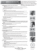
MOUNTING ROTOR TO HUB
1. Attach the rotors to the hubs with the sup-
plied M5 x 12 bolts. As indicated by the chart
above, the larger rotor goes on the front hub.
The size of the rotor in millimeters is stamped
on each rotor. Torque the rotor bolts to 40-50
In-Lbs (4.5-6 Nm.) Be sure that the rotor is
installed with the ROTATION arrow pointing in
the same direction as forward wheel rotation
(see Fig. 1.)
Note that the Lefty front hub uses a plastic
seal which goes between the rotor and the
large cartridge bearing to guard against water
and dirt. Make sure that the Lefty seal is in
place before bolting on the rotor, and that the
attached rotor will hold the seal in place.
2. Periodically check the bolts holding the
brake rotors to the hubs for tightness.
INSTALLING AND REMOVING BRAKE PADS
CAUTION: THE BRAKE PADS EQUIPPED WITH THE CODA EXPERT DISC BRAKE SYSTEM
ARE MADE OF A KEVLAR BASED COMPOUND SPECIFICALLY DESIGNED FOR USE WITH
THE BRAKE SYSTEM’S STAINLESS STEEL BRAKE ROTORS. USE ONLY CODA REPLACE-
MENT BRAKE PADS (KIT # QBDPAD/GRN) WHICH ARE MATCHED TO THE BRAKE ROTOR
MATERIAL. NOTE THAT OLDER SQUARE CODA COMPETITION DISC BRAKE PADS ARE NOT
COMPATIBLE WITH THE NEWER CODA EXPERT AND COMPETITION DISC BRAKE ROTORS
(171MM AND 151MM DIAMETERS.) HOWEVER, THE NEW RECTANGULAR CODA DISC BRAKE
PADS MAY BE USED ON ALL CODA DISC BRAKE SYSTEMS, REGARDLESS OF ROTOR SIZE.
THE NEW RECTANGULAR CODA COMPETITION DISC BRAKE PADS ARE ALSO RIGHT AND
LEFT SIDE SPECIFIC. THE PAD MUST BE INSERTED SO THAT THE ENTIRE SURFACE OF THE
PAD MAKES CONTACT WITH THE ROTOR. SEE THE ILLUSTRATION BELOW FOR IDENTIFICA-
TION.
CAUTION: USE ONLY GENUINE CODA
REPLACEMENT DISC BRAKE PADS. USE OF
OTHER BRAKE PADS WILL VOID THE
BRAKE’S WARRANTY AND COULD LEAD TO
POSSIBLE BRAKE FAILURE.
1. The CODA Expert Disc Brake pads are held
in the caliper by magnetic force. The pads have
a steel backing plate and must be installed with
this steel plate facing into the body of the caliper
and the abrasive side facing the rotor, which
runs between the two pads.
2. The CODA Expert Disc Brake pads are right and left side specific. The pad must be inserted so
that the entire surface of the pad makes contact with the rotor. See Fig. 2 for left and right pad identi-
fication.
4.
Fig. 1
Fig. 2
LEFT EXPERT PAD
RIGHT EXPERT
CODAExpertDBUsManCE.qxd 8/21/00 3:50 PM Page 4

3. When installing the pads, it may be nec-
essary to back the caliper adjusters out by
turning them counter-clockwise with a
5mm hex wrench. This will allow enough
clearance in the caliper slot to be able to
slide each pad into its respective side of
the caliper. The 5mm Allen screw on the
bleed screw side of brake adjusts the posi-
tion of the piston activated pad, while the
5mm hex screw on the other side of the
brake adjusts the position of the fixed pad.
Note that the fixed (right) side pad adjuster
does not have a stop and can be com-
pletely unscrewed from the caliper. If this
happens, put a drop of Loctite 242 (blue)
on the threads and reinstall the pad
adjuster into the caliper.
4. Install the pads one at a time by simply
holding the tab on each pad and sliding
each pad into the rotor slot and then into
the square hole on each side of the slot
(see Fig. 3.) The pin on each piston must
mate with the hole in the back of each
pad, and the tabs of each pad will stick out
of the caliper near the lower caliper
mounting bolt. Again, make sure that the
correct pad is installed in each side of the
caliper.
5. Pads can be removed by simply grasping the steel tab on each, lifting the pad out of the square
hole in the caliper, and maneuvering the pad out through the rotor slot in the body of the caliper.
MOUNTING BRAKE LEVERS
Note: The CODA Expert Disc Brake system comes assembled with the left brake lever attached to
the front caliper and the right brake lever to the rear caliper. If you would like to reverse this arrange-
ment, simply flip the lever over and install it on the other side of the handlebar. The brake levers are
symmetrical and can be used on either side of the bar. The lever clamp bolt and nut may also be
removed and reversed so that the bolt is accessible from either side of the lever.
1. Slide the brake levers onto the handlebar with brake lines pointing toward the center of the handle-
bar, as you would any standard mountain bike type brake lever. Generally, push button type shifters
will need to be installed on the bar before the brake levers, while twist shifters will go on after the
brake levers.
2. Tighten the shifters and install the grips per the manufacturers’ instructions.
3. Once the brake levers and shifters have been positioned as desired, tighten the brake lever bolts to
72-108 In-Lbs (8-12 Nm.)
4. The reach of each brake lever can be adjusted closer by turning the 2mm hex head lever adjusting
screw clockwise. This will also move the pads closer to the brake rotor. If you adjust the reach of the
brake levers after having set up the brakes, it may be necessary to readjust the pad clearance with
the two 5mm hex screws on the caliper. See the "PAD ADJUSTMENT" section below.
WARNING: Do not remove the 2mm brake lever adjusting screw from the lever body. It holds the
lever pivot in place. Removal of the brake lever adjusting screw could result in the brake lever falling
out of the master cylinder, with attendant loss of braking and risk of injury or death.
5.
Fig. 3
CODAExpertDBUsManCE.qxd 8/21/00 3:50 PM Page 5

Note that the CODA Expert Disc Brake levers and
brake lever blades are not interchangeable with those
from the CODA Competition Disc Brake.
MOUNTING OF CALIPERS
1. Before installing the calipers, install each wheel into
the frame or fork dropouts ensuring that the axle is cor-
rectly seated (the brake rotor should be on the caliper
mounting side.) Tighten the quick release skewer firm-
ly.
CAUTION: FOR INSTRUCTIONS ON THE CORRECT
USE OF QUICK RELEASES, PLEASE SEE SECTION
6 (HOW THINGS WORK) OF THE CANNONDALE
OWNER’S MANUAL OR THE QUICK RELEASE
SECTION OF YOUR BICYCLE’S MANUAL.
2. Make sure that the brake pads are correctly installed
in the caliper and that the brake pads do not protrude
into the slot in the caliper. If necessary the 5mm hex
pad adjusting screws on each side of the caliper
should be backed out for maximum pad clearance.
3. Hook the caliper over the brake rotor, so that the
bleed screw is to the outside, or left side, of the bike. Place two shims per bolt between the caliper
and the frame mounting tabs, and thread in the supplied M6 x 18mm bolts. Tighten the bolts to 69-78
In-Lbs (8-9 Nm.)
4. Check that the rotor is centered in the caliper. If it is not, add or remove shims from each caliper
mounting bolt until the rotor is centered between the pads (see Fig. 4.) Add or remove shims evenly,
so that both bolts have the same number of shims. Adjust the caliper up and down so that the brake
pads sit as high as possible on the rotor while making full contact. Do not allow the brake pads to sit
above the outside edge of the rotor.
5. When adjusted, tighten both bolts to 69-78 In-Lbs (8-9 Nm.) You should periodically check the
caliper bolts for tightness.
6. Repeat the procedure for the other brake caliper.
CAUTION: ATTACH THE BRAKE LINES TO THE FRAME AND FORK SO THAT THEY DO NOT
CONTACT THE WHEEL OR TIRE, OR INTERFERE WITH THE TRAVEL OF THE SUSPENSION
OR THE ACTION OF THE STEERING. USE THE SUPPLIED GUIDE CLIPS (KIT # QBDC/) TO
ATTACH THE BRAKE LINES TO THE BIKE’S EXISTING CABLE HOUSING STOPS. ALSO BE
SURE THAT THE BRAKE LINES ARE NOT SO LONG AS TO POSSIBLY SNAG ON ANYTHING
WHILE RIDING. SEE THE SECTION BELOW ON SHORTENING BRAKE LINES.
PAD ADJUSTMENT
1. When the system is fully installed or whenever you change the pads, bleed the system, or adjust
the brake lever reach, you will need to adjust the position of the pads. On each caliper, you will need
to screw in the fixed side pad adjuster (on the right side of the brake caliper) with a 5mm hex wrench
just until the pad begins to slightly brush the rotor AND LEAVE IT THERE. The piston side pad
adjuster (on the left side of the caliper, next to the bleed screw) should then be adjusted using the
5mm hex screw to achieve the desired brake lever travel and feel.
This setup will allow the brake pad to slightly brush the rotor for the first ride or until the pads are
properly bedded in, but will position the fixed pad very close to the rotor (where it needs to be) and
will allow the pads to wear in parallel to the rotor.
6.
Fig. 4
CODAExpertDBUsManCE.qxd 8/21/00 3:50 PM Page 6

2. If the pads have been previously bedded in to the rotors and are simply being readjusted after
brake bleeding or service, you should still screw in the fixed side pad adjuster just until it begins to
slightly brush the rotor and then back it out counter-clockwise by quarter turns until the brushing
sound stops. The fixed side pad must be set very close to the rotor for optimal brake power. Then set
the piston side pad for desired brake lever travel and feel.
3. Check that the brakes work well and that all
parts and brake lines are tight and secure before
riding. Ride cautiously at first while you get used to
your new brakes, as hydraulic disc brakes have
very different braking characteristics than cable-
actuated rim brakes. Remember that new pads will
require 30-40 full stops to achieve full stopping
power. The bedding-in process can be accelerated
by first riding 200-300 meters slowly around a flat
smooth area (such as an empty parking lot) with
the brakes applied so that they drag. Then make
20-30 full stops from about 10 miles / hour (15.5
Km / h).
BRAKE PAD RETAINER
Whenever the wheel is removed from the bicycle,
insert the CODA Brake Pad Retainer (part #
QC111/) into the caliper to ensure that the brake
pads are not dislodged from the caliper. First,
check to make sure that the pad retainer is clean
and free of oil, grease, or brake fluid. Insert the
edge of the retainer with the wide opening all the
way into the slot in the caliper. The two round
knobs will secure the retainer in the caliper. See
Fig. 5.
Be sure that both pads are in the caliper when
reinstalling the wheel.
BRAKE SYSTEM WEAR INDICATORS
Replace CODA brake pads when they have worn
to the point that the caliper piston pin hole goes all
the way through the pad (see Fig. 6.)
The CODA rotors are also subject to wear and need to be replaced when they are .068" (1.73mm) or
thinner. When new they measure .078" (1.98mm) thick.
The CODA hydraulic fluid, developed by NASA, is not effected by extreme temperatures and does not
absorb moisture, so does not break down over time.
SECTION II: SERVICE
SHORTENING BRAKE LINES
Note: It is best to shorten the Expert Disc Brake hydraulic line at the brake lever end.
CAUTION: REMOVE WHEEL AND PADS FROM THE SYSTEM BEFORE DISCONNECTING
BRAKE LINES! MAKE SURE THAT THE PADS AND BRAKE ROTOR STAY CLEAN AND FREE
OF OIL, GREASE, AND BRAKE FLUID. BEFORE HANDLING THE BRAKE PADS OR ROTOR,
7.
Fig. 5
Fig. 6
NEW PAD
WORN OUT PAD
CODAExpertDBUsManCE.qxd 8/21/00 3:50 PM Page 7

CLEAN THE OUTSIDE OF THE BRAKE LINES, CALIPER, AND LEVER WITH THE DETERGENT
AND HOT WATER SOLUTION, RINSE WITH CLEAN WATER, AND ALLOW TO AIR DRY, AND
WASH YOUR HANDS! IF THE ROTORS ARE CONTAMINATED WITH BRAKE FLUID, CLEAN
THEM WITH THE DETERGENT AND HOT WATER SOLUTION, RINSE WITH CLEAN WATER,
AND ALLOW TO AIR DRY. IF THE PADS ARE CONTAMINATED, DISCARD THEM AND USE NEW
PADS.
1. Thread the caliper pad clearance adjusters all the way out (for maximum pad clearance.)
2. Remove the wheels and the brake pads from the bike. Pull back the plastic cover at the brake
lever, exposing the brake line threaded sleeve fitting.
3. Using an 8mm wrench, unthread the fitting
and pull the brake line out of the brake lever
master cylinder. Slide the cover and threaded
fitting up the brake line well clear of where
you’ll be cutting.
Do not activate the brake lever with the line
disconnected!
4. Use a razor knife or hydraulic tubing cutter
to trim the hydraulic line to the desired length.
Cut the end of the tubing square and at least
1cm from the end to avoid cutting the old tub-
ing insert. Do not use a serrated knife or a pli-
ers-type cutter, as these will damage the end
of the brake line.
5. Slip a new compression ferrule over the cut
end of the tubing, on far enough so that
0.5mm of tubing extends through the ferrule.
Orient the fitting with the sharp edge toward the threaded sleeve (away from the brake lever master
cylinder). Then press the barbed end of a new hydraulic line insert into the end of the tubing. There
should be no more than 1.6mm between the end of the tubing insert and the compression ferrule.
See Fig. 7.
Important: Use a new compression ferrule and line insert each time the brake line is shortened.
Several spares are included with the brake set.
6. Press the end of the tubing into the master cylinder until the ferrule makes contact with the inside
of the master cylinder, checking to make sure that the brake line is clear of tires and wheels or any
other possible snags. Slide the threaded sleeve up to the master cylinder and screw it in, being care-
ful not to cross thread the fitting. Tighten the threaded sleeve to 69-78 In-Lbs. (8-9 Nm.)
7. Tug gently on the brake line to make sure the fitting is fully threaded in.
8. Before reinstalling the wheels or brake pads, or riding the bike, you must bleed the brake system.
See the next section on brake bleeding for instructions.
BRAKE SYSTEM BLEEDING AND FLUID CHANGE
CAUTION: USE ONLY CODA DISC BRAKE FLUID. OTHER TYPES OF BRAKE FLUID MAY NOT
BE COMPATIBLE WITH THE EXPERT DISC’S SEALS AND HYDRAULIC SYSTEM.
CAUTION: REMOVE WHEEL AND PADS FROM THE SYSTEM BEFORE BLEEDING THE BRAKE
SYSTEM! MAKE SURE THAT THE PADS AND BRAKE ROTOR STAY CLEAN AND FREE OF OIL,
GREASE, AND BRAKE FLUID. BEFORE HANDLING THE BRAKE PADS OR ROTOR, CLEAN
8.
Fig. 7
CODAExpertDBUsManCE.qxd 8/21/00 3:50 PM Page 8

THE OUTSIDE OF THE BRAKE LINES, CALIPER, AND LEVER WITH THE DETERGENT AND
HOT WATER SOLUTION, RINSE WITH CLEAN WATER, AND ALLOW TO AIR DRY, AND WASH
YOUR HANDS! IF THE ROTORS ARE CONTAMINATED WITH BRAKE FLUID, CLEAN THEM
WITH THE DETERNGENT AND HOT WATER SOLUTION, RINSE WITH CLEAN WATER, AND
ALLOW TO AIR DRY. IF THE PADS ARE CONTAMINATED, DISCARD THEM AND USE NEW
PADS.
Whenever the system is opened up, the line should be bled out. If there is air in the system, the lever
will feel soft and braking power will be reduced. When properly bled and adjusted you should be able
to feel, through the lever, the pads solidly hitting the rotor. The brake should not feel spongy or
squishy.
The brake bleeding kit (part # QBDS/ included with the brake system) includes 4 oz. CODA disc
brake fluid, 2 - 10" lengths of tubing, 20cc syringe, and 4 compression ferrules and line inserts.
1. Remove the wheels and brake pads from the bike if you haven’t already done so.
2. Thread the pad clearance adjuster on the left side of the caliper all the way out counter-clockwise.
Also make sure that the brake lever is fully extended and that the 2mm lever reach adjusting screw is
not compressing the brake lever piston. Insert the vinyl handle of a T-handle hex wrench into the slot
in the caliper and using a 5mm hex wrench, screw in the right side pad adjuster so that the vinyl han-
dle is held between the pistons. Make sure that the vinyl handle sits against the flat faces of the pis-
tons and not against the pins in the center of the pistons.
3. Remove the rubber bleed screw covers from the caliper and master cylinder. If they are missing,
make sure that the hole in the bleed screw is clean and free from mud or other contamination. Use a
1.5mm hex wrench or similar to remove dirt. Failure to clean out the bleed screw before bleeding will
result in contamination of the fluid which will dramatically reduce the life of the internal seals.
4. Loosen the brake lever clamping bolt and turn the lever on the handlebar so that the bleed screw is
oriented vertically up. Attach one hose to the master cylinder bleed screw and put the other end of
the hose into a clean dry bottle.
Note: It may be easiest to hang the receptacle bottle on the handlebar with wire, a rubber band, or an
old spoke. Be sure that both the fluid and the container stay clean. Do not re-use fluid which has
been contaminated.
5. Attach the second hose to the syringe and fill the syringe with fluid. Invert the syringe and squeeze
the syringe until all air is evacuated from the syringe and hose. Attach the hose from the syringe to
the caliper bleed screw.
6. Use a 7mm wrench to open the master cylinder bleed screw 1/2 turn. Then use a 5mm hex wrench
to hold the piston side pad adjuster in place and use the 7mm wrench to open the caliper bleed screw
1/2 turn. Begin squeezing the syringe. Continue squeezing until the bleed screws are closed in step
#10.
Note: if the syringe runs out of fluid, simply close the bleed screw on the caliper. Detach the hose
from the bleed screw, refill the syringe, and start again.
7. While squeezing the syringe, begin tapping the caliper with the plastic handle of a screwdriver (the
shock from the tapping will help to dislodge air pockets within the caliper). During this step, you may
start seeing air bubbles moving through the upper length of hose and into the receptacle bottle.
8. Start tapping on the brake line, slowly moving up the line towards the brake lever, all the while
squeezing the syringe.
9. Tap the master cylinder on the brake lever, and then slowly pull and release the brake lever several
times to evacuate any air from the piston in the master cylinder, while continuing to push fluid through
the system.
9.
CODAExpertDBUsManCE.qxd 8/21/00 3:50 PM Page 9

10. Once you are sure that all air has been evacuated from the system, close the bleed screw on the
caliper, and then the one on the master cylinder. Tighten the bleed screws to 52-61 In-Lbs (6-7 Nm.)
The caliper bleed screw is easiest tightened if the piston side pad adjuster is being held with a 5mm
hex wrench. Remove the hoses from the bleed screws, and return the fluid in the receptacle bottle to
the source bottle only if it does not appear contaminated or discolored.
11. Reposition the brake lever and tighten lever clamp bolt to 72-108 In-Lbs (8-12 Nm.) Pull firmly on
the brake lever several times and check for leakage at the bleed screws and brake line fittings. The
brake should feel firm as you pull against the vinyl T-handle. Once you are sure that there are no sys-
tem leaks and all air has been removed from the brake, remove the vinyl T-handle from the caliper
slot.
12. Before handling the brake pads or rotor, clean the outside of the lines, caliper, and lever with the
detergent / hot water solution, and wash your hands. Also be sure to clean the slot in the caliper and
the pistons with detergent and hot water. Rinse washed parts and allow to air dry, then re-install the
pads and the wheel.
13. Adjust the brake lever reach with the 2mm hex screw and set the pad clearance using the two
5mm hex pad adjusters as described in the "PAD ADJUSTMENT" section above. Remember that the
fixed side pad must be set as closely as possible to the rotor without dragging.
Note: Also clean the syringe and hoses with the detergent solution. Don’t leave fluid in the syringe, as
this will damage the seal in the syringe.
REPLACEMENT OF BRAKE LINE
CAUTION: USE ONLY CODA DISC BRAKE LINE REPLACEMENT KIT (PART # QBDT/110).
OTHER BRAKE LINES MAY NOT BE COMPATIBLE WITH CODA BRAKE FLUID OR MAY BURST
UNDER PRESSURE.
CAUTION: REMOVE WHEEL AND PADS FROM THE SYSTEM BEFORE DISCONNECTING
BRAKE LINES! MAKE SURE THAT THE PADS AND BRAKE ROTOR STAY CLEAN AND FREE
OF OIL, GREASE, AND BRAKE FLUID. BEFORE HANDLING THE BRAKE PADS OR ROTOR,
CLEAN THE OUTSIDE OF THE BRAKE LINES, CALIPER, AND LEVER WITH THE DETERGENT
AND HOT WATER SOLUTION, RINSE WITH CLEAN WATER, AND ALLOW TO AIR DRY, AND
WASH YOUR HANDS! IF THE ROTORS ARE CONTAMINATED WITH BRAKE FLUID, CLEAN
THEM WITH THE DETERGENT AND HOT WATER SOLUTION, RINSE WITH CLEAN WATER,
AND ALLOW TO AIR DRY. IF THE PADS ARE CONTAMINATED, DISCARD THEM AND USE NEW
PADS.
The CODA Disc Brake line replacement kit includes new brake line, replacement compression fer-
rules, and hydraulic line inserts.
Note: When replacing an entire brake line, it is easiest to attach the new line to the caliper first, and
then to the brake lever master cylinder. You will also need to cut off and discard the silver line fittings
which are installed in the ends of the new hydraulic line, they are only for use on the Competition
brake.
The procedure for replacement of the brake line is identical to that of shortening the brake line, except
that the line must also be refit at the caliper. On the Expert Disc Brake, the hydraulic line uses identi-
cal compression fittings on each end.
1. First, remove the hydraulic line from the master cylinder as instructed in steps 1-3 of the "SHORT-
ENING BRAKE LINES" section above.
2. With an 8mm wrench, unscrew the threaded fitting from the caliper and pull the line out.
3. Using the old line as a guide, cut the new line to length. Note that the new line is 110" long, so that
10.
CODAExpertDBUsManCE.qxd 8/21/00 3:50 PM Page 10

one replacement line can be cut to replace both front and rear lines simultaneously. Be sure to cut off
and discard the silver fittings which are already installed in the ends of the new hydraulic line before
figuring the length of the new line.
4. Slip a new compression ferrule over the caliper end of the new tubing, on far enough so that at
least 3mm of tubing extends through the ferrule. Orient the fitting with the sharp edge toward the
threaded sleeve (away from the caliper). Then press the barbed end of a new hydraulic line insert into
the end of the tubing. Press the end of the tubing into the caliper until it stops. Slide the threaded
sleeve down to the caliper and screw it in, being careful not to cross thread the fitting. Tighten the
threaded sleeve to 69-78 In-Lbs. (8-9 Nm.) Slip the black plastic cover from the old line over the
threaded sleeve
Go to step 5 of the "SHORTENING BRAKE LINES" section to complete the procedure. Once the new
line is installed, the system must be bled before the bike is ridden.
PERIODIC MAINTENANCE
Perform the following steps every few months or as needed:
1. Lubricate the brake lever blade pivot with thick oil or grease.
2. Check to make sure that all bolts are tight to torque specification.
3. Remove the brake pads and check them for wear. See information above about the wear indicator
on the brake pads. Clean the slot in the caliper body of mud and other contamination. Do not use
compressed air to clean out the slot in the caliper body. Finish the job by cleaning the caliper body
and slot with the detergent and hot water solution.
WARNINGS FOR THE CODA EXPERT DISC BRAKE:
THE CODA EXPERT DISC BRAKE CALIPERS SHOULD ONLY BE MOUNTED TO A FRAME OR
FORK WITH ORIGINAL EQUIPMENT INTEGRAL DISC BRAKE CALIPER MOUNTS. DO NOT
ATTEMPT TO WELD, CLAMP, OR OTHERWISE ATTACH A DISC BRAKE MOUNT TO A FRAME
OR FORK. DO NOT USE CALIPER MOUNTING ADAPTERS OR BRACKETS UNLESS THEY ARE
MANUFACTURED BY OR SPECIFICALLY RECOMMENDED BY CODA. USE OF NON-STANDARD
BRAKE CALIPER MOUNTS PLACES THE RIDER AT RISK OF PERSONAL INJURY OR DEATH.
THE BRAKE CALIPER PADS MUST MAKE FULL CONTACT WITH THE BRAKE ROTOR. EACH
WHEEL MUST BE INSERTED COMPLETELY INTO THE DROPOUTS AND SECURELY CLAMPED
IN PLACE. ADDITIONALLY, THE EXPERT’S BRAKE PADS ARE RIGHT AND LEFT SPECIFIC. IF
THE SURFACES OF THE BRAKE PADS ARE NOT ALIGNED WITH THE ROTOR, BRAKE
POWER MAY BE INSUFFICIENT, RESULTING IN A LOSS OF CONTROL OF THE BICYCLE AND
RISK OF INJURY OR DEATH TO THE RIDER.
INSPECT THE BRAKE LINES REGULARLY FOR ABRASIONS OR DAMAGE. DO NOT KINK OR
BEND BRAKE LINES. IMMEDIATELY REPLACE ANY DAMAGED BRAKE LINES WITH GENUINE
11.
CODAExpertDBUsManCE.qxd 8/21/00 3:50 PM Page 11

CODA REPLACEMENT BRAKE LINE ONLY. A DAMAGED BRAKE LINE MAY BURST, RESULT-
ING IN A SUDDEN LOSS OF BRAKING POWER AND THE RIDER’S POSSIBLE INJURY OR
DEATH.
THE CODA EXPERT DISC BRAKE PADS REQUIRE 30 TO 40 COMPLETE STOPS TO BED IN
AND ACHIEVE FULL STOPPING POWER WHEN NEW. ADDITIONALLY, CODA EXPERT DISC
BRAKES SHOULD BE RIDDEN CAUTIOUSLY ON FLAT GROUND UNTIL THE RIDER IS ACCLI-
MATED TO THE FEEL AND POWER OF DISC BRAKES.
BE SURE THAT BOTH BRAKE PADS ARE IN THE CALIPER FOLLOWING WHEEL REMOVAL
AND WHEN REINSTALLING WHEELS ON THE BIKE. ALSO, DO NOT CYCLE THE BRAKE
LEVERS WITHOUT BOTH BRAKE PADS AND A ROTOR (OR PLASTIC PAD RETAINER)
INSTALLED IN THE CALIPER. THE PISTON MAY BE PUMPED PAST ITS SEALS, RESULTING IN
A LOSS OF HYDRAULIC FLUID.
DISC BRAKE ROTORS, CALIPERS, AND PADS GET EXTREMELY HOT UNDER USE! SEVERE
INJURY COULD RESULT FROM CONTACT WITH A HOT BRAKE. MIND YOUR LEGS AS WELL
AS YOUR HANDS, AND BE SURE TO ALLOW THE BRAKES TO COOL COMPLETELY BEFORE
SERVICING.
WHEN WASHING A CODA DISC BRAKE EQUIPPED BICYCLE, BE CAREFUL NOT TO SPRAY
OR WIPE GREASE, OIL, OR CHAIN LUBRICANT FROM THE BIKE’S HUBS OR DRIVETRAIN
ONTO THE BRAKE ROTOR OR PADS. ADDITIONALLY, DO NOT USE ANY TYPE OF SPRAY
LUBRICANT, WAX, OR POLISH NEAR THE BRAKE ROTORS OR PADS.
ALWAYS WEAR SAFETY GLASSES WHEN SERVICING THE BRAKE SYSTEM OR OTHER COM-
PONENTS OF YOUR BICYCLE. SEE THE CODA DISC BRAKE FLUID BOTTLE FOR WARNINGS
ABOUT AVOIDING CONTACT WITH EYES.
CODA WARRANTY
All CODA components are warrantied against manufacturing defects in materials and/or workmanship
for a period of one year from the date of original retail purchase.
Not covered under warranty is damage resulting from improper installation, adjustment, or mainte-
nance, lack or maintenance, alterations, crashes, or use judged by CODA to be excessive or abusive.
For warranty related questions or for more information on this or any CODA product, please feel free
to contact us.
USA and Canada: (888) CODA-USA
Europe (EC): (31) 541-573580
Japan: (81) 722-99-9399
Australia: (61) 2-9979-5851
USA and Canada: [email protected]
Europe (EC): [email protected]
http://www.codausa.com
http://www.cannondale.comz ~
APPENDIX
List of CODA Expert Disc Brake specific replacement parts kits:
12.
CODAExpertDBUsManCE.qxd 8/21/00 3:50 PM Page 12

QBDS/ Bleeder / service kit
QBDPAD/GRN Brake pads, pair
QC111/ Brake Pad Retainer, orange, for use when wheel is not installed on bike
QBDRF/171 Rotor for Expert Disc Brake, front, 171mm diameter
QBDRR/151 Rotor for Expert Disc Brake, rear, 151mm diameter
QBDR/MHW Rotor bolts, pack of 8 bolts
QBDC/MHW Caliper bolts and shims, 4 bolts and 32 shims
QBDT/110 Replacement hydraulic line, 110" long with fittings
QBDC/ Hydraulic line clamp kit
QBDF/8 Hydraulic fluid for CODA disc brake, 8 oz. bottles, pack of 4
QBDCF/10 Compression ferrules and line inserts, pack of 10
QBDCS/2 Compression screws, holds tubing into caliper and lever, pack of 2
QBDBS/2 Bleeder screws, pack of 2
QBDCAP/BLEEDER Bleeder screw caps, rubber, pack of 4
QBDELEV/ Expert Disc Brake lever blade, each (L and R are identical)
QBDECAL/ Expert Disc Brake caliper, each (F and R are identical)
QBDEMAS/ Expert Disc Brake master cylinder complete with lever blade (L and R are identi-
cal)
13.
CODAExpertDBUsManCE.qxd 8/21/00 3:50 PM Page 13
/