GE DCF & DCD: Durable fixtures designed for challenging environments, offering reliable lighting solutions for streets, parking lots, and other outdoor areas. These fixtures feature rugged construction, energy-efficient LED technology, and a range of mounting options for versatile installation. With long-lasting performance and minimal maintenance requirements, GE DCF & DCD provide dependable illumination for various outdoor applications.
GE DCF & DCD: Durable fixtures designed for challenging environments, offering reliable lighting solutions for streets, parking lots, and other outdoor areas. These fixtures feature rugged construction, energy-efficient LED technology, and a range of mounting options for versatile installation. With long-lasting performance and minimal maintenance requirements, GE DCF & DCD provide dependable illumination for various outdoor applications.


-
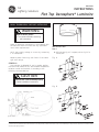 1
1
-
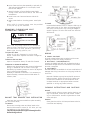 2
2
-
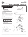 3
3
-
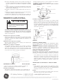 4
4


GE DCF & DCD: Durable fixtures designed for challenging environments, offering reliable lighting solutions for streets, parking lots, and other outdoor areas. These fixtures feature rugged construction, energy-efficient LED technology, and a range of mounting options for versatile installation. With long-lasting performance and minimal maintenance requirements, GE DCF & DCD provide dependable illumination for various outdoor applications.
Ask a question and I''ll find the answer in the document
Finding information in a document is now easier with AI
in other languages
- français: GE DCF & DCD Guide d'installation
Related papers
-
GE DCF & DCD Installation guide
-
GE H9 Luminaire Installation guide
-
-
-
-
-
-
-
-
Other documents
-
BAZZ 606R30M6 Installation guide
-
Signify Form Ten Square Area LED EH14/19L G3 Install Instructions
-
CREE LIGHTING IG-B Installation guide
-
Acuity Brands Lithonia Lighting KSF Installation guide
-
 AccuLite Areos Installation guide
-
Eaton Crouse-hinds series Installation & Maintenance Information
-
-
-
Day-Brite CFI FluxSpace LED Linear Install Instructions
-
 VENTURE LIGHTING BO0003 LED Sensor Mounting Kit User manual

