Page is loading ...

DIRECT-VENT FIREPLACE
OWNER’S OPERATION AND INSTALLATION MANUAL
DVFE34 (NATURAL)
ELECTRONIC IGNITION
Save this manual for future reference.
FOR YOUR SAFETY
WHAT TO DO IF YOU SMELL GAS
• Do not try to light any appliance.
• Do not touch any electrical switch
• Do not use any phone in your building.
• Immediately call your gas supplier from a
neighbor’s phone. Follow the gas supplier’s
instructions.
• If you cannot reach your gas supplier, call
the fire department.
WARNING: Improper installation,
adjustment, alteration, service, or
maintenance can cause injury or
property damage. Refer to this
manual for correct installation and
operational procedures. For assis-
tance or additional information con-
sult a qualified installer, service
agency, or the gas supplier.
This appliance may be installed in an aftermarket* manufactured (mobile) home,
where not prohibited by state or local codes.
WARNING: If the information in this manual is
not followed exactly, a fire or explosion may
result causing property damage, personal in-
jury, or loss of life.
FOR YOUR SAFETY
Do not store or use gasoline or other flammable
vapors and liquids in the vicinity of this or any
other appliance.
— Installation and service must
be performed by a qualified in-
staller, service agency, or the gas
supplier.
— This appliance is only for use
with the type of gas indicated on
the rating plate. This appliance is
not convertible for use with other
gases, unless a certified kit is
used.
*Aftermarket: Completion of sale, not for purpose of resale, from the manufacturer.
For more information, visit www.desatech.com

2
107205
DIRECT-VENT FIREPLACE
For more information, visit www.desatech.com
SAFETY
INFORMATION
1. This appliance is only for use with the
type of gas indicated on the rating plate.
This appliance is not convertible for use
with other gases unless a certified kit
is used.
2. For propane/LP fireplace, do not place
propane/LP supply tank(s) inside any
structure. Locate propane/LP supply
tank(s) outdoors. To prevent perfor-
mance problems, do not use propane/LP
fuel tank of less than 100 lbs. capacity.
3. If you smell gas
• shut off gas supply
• do not try to light any appliance
• do not touch any electrical switch; do
not use any phone in your building
• immediately call your gas supplier
from a neighbor’s phone. Follow the
gas supplier's instructions
• if you cannot reach you gas supplier,
call the fire department.
4. Never install the fireplace
• in a recreational vehicle
• where curtains, furniture, clothing, or
other flammable objects are less than
42" from the front, top, or sides of
the fireplace
• in high traffic areas
• in windy or drafty areas
5. This fireplace reaches high tempera-
tures. Keep children and adults away
from hot surfaces to avoid burns or
clothing ignition. Fireplace will remain
hot for a time after shutdown. Allow sur-
faces to cool before touching.
6. Carefully supervise young children
when they are in the room with fireplace.
7. Do not modify this fireplace under any
circumstances. Any parts removed for
servicing must be replaced prior to op-
erating fireplace.
8. Turn fireplace off and let cool before
servicing, installing, or repairing. Only
a qualified service person should in-
stall, service, or repair this fireplace.
Have fireplace inspected annually by a
qualified service person.
9. You must keep control compartments,
burners, and circulating air passages
clean. More frequent cleaning may be
needed due to excessive lint and dust
from carpeting, bedding material, etc.
Turn off the gas valve and pilot light
before cleaning fireplace.
10. Have venting system inspected annu-
ally by a qualified service person. If
needed, have venting system cleaned
or repaired. See Cleaning and Mainte-
nance, page 26.
11. Keep the area around your fireplace
clear of combustible materials, gaso-
line, and other flammable vapor and
liquids. Do not run fireplace where
these are used or stored. Do not place
items such as clothing or decorations
on or around fireplace.
12. Do not use this fireplace to cook food
or burn paper or other objects.
13. Do not use any solid fuels (wood, coal,
paper, cardboard, etc.) in this fireplace.
Use only the gas type indicated on fire-
place nameplate.
14. This appliance, when installed, must be
electrically grounded in accordance
with local codes or, in the absence of
local codes, with the National Electri-
cal Code, ANS/NFPA 70, or the Cana-
dian Electrical Code, CSA C22.1.
15. Do not obstruct the flow of combus-
tion and ventilation air in any way. Pro-
vide adequate clearances around air
openings into the combustion chamber
along with adequate accessibility clear-
ance for servicing and proper operation.
16. Do not install fireplace directly on car-
peting, vinyl tile, or any combustible
material other than wood. The fireplace
must set on a metal or wood panel ex-
tending the full width and depth of the
fireplace.
17. Do not use fireplace if any part has been
exposed to or under water. Immediately
call a qualified service person to ar-
range for replacement of the unit.
18. Do not operate fireplace if any log is
broken.
19. Do not use a blower insert, heat ex-
changer insert, or other accessory not
approved for use with this fireplace.
20. Do not operate fireplace with glass door
removed, cracked, or broken.
IMPORTANT: Read this owner’s
manual carefully and completely
before trying to assemble, oper-
ate, or service this fireplace. Im-
proper use of this fireplace can
cause serious injury or death from
burns, fire, explosions, electrical
shock, and carbon monoxide
poisoning.
WARNING: Any change to
this fireplace or its controls can
be dangerous.
WARNINGS
DANGER: Carbon monoxide
poisoning may lead to death!
This fireplace is a vented product. This
fireplace will not produce any gas leakage
into your home if properly installed. This
fireplace must be properly installed by a
qualified service person. The glass door
must be properly seated and sealed. If this
unit is not properly installed by a qualified
service person with glass door properly
seated and sealed, gas leakage can occur.
Carbon Monoxide Poisoning: Early signs
of carbon monoxide poisoning resemble the
flu, with headaches, dizziness, or nausea. If
you have these signs, the fireplace may not
have been installed properly. Get fresh air
at once! Have fireplace inspected and ser-
viced by a qualified service person. Some
people are more affected by carbon monox-
ide than others. These include pregnant
women, people with heart or lung disease or
anemia, those under the influence of alcohol,
and those at high altitudes.
Propane/LP gas and natural gas are both
odorless. An odor-making agent is added to
each of these gases. The odor helps you
detect a gas leak. However, the odor added
to these gases can fade. Gas may be present
even though no odor exists.
Make certain you read and understand all
warnings. Keep this manual for reference. It
is your guide to safe and proper operation of
this fireplace.

3
107205
OWNER’S MANUAL
For more information, visit www.desatech.com
PRODUCT
IDENTIFICATION
Install and use fireplace with care. Follow all
local codes. In the absence to local codes, use
the current National Fuel Gas Code, ANS
Z223.1, also known as NFPA 54* (USA) or
the current CAN/CGA-B149[.1 or .2] Instal-
lation Codes (Canada).
*Available from:
American National Standards Institute, Inc.
1430 Broadway
New York, NY 10018
National Fire Protection Association, Inc.
Batterymarch Park
Quincy, MA 02269
LOCAL CODES
OPERATION
This direct-vent fireplace is clean burning and
vents easily through outside walls or vertically
using outside air for combustion. Heat is gen-
erated by both realistic flames and glowing
embers. This electronic ignition model re-
quires household electricity to operate.
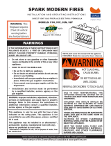
Figure 1 - FMI Direct-Vent Fireplace DVFE Series
Glass Door
Assembly
Blower Adjustment
(Optional Installation)
ON/OFF Remote Switch
(Optional Installation)
Valve
Pilot
Assembly
Log Set
Grate
Assembly
Lava Rock
Glowing Embers
Top Louver
Panel
Lower Louver Panel
Vent Opening
Nailing
Flange
Standoff
Rear
Burner
GLOSSARY OF
TERMS
Chase - A boxlike enclosure to protect
venting from the elements when the venting
run is on the outside of a structure.
Mastic - A pliable sealant for use around the
vent terminal.
Snorkel Termination - A box that raises the
horizontal termination above ground level
clearances.
Vent Terminal - Mounted on an outside
wall or roof to separate the inlet and outlet of
the vent system and protect it from weather.
Vinyl Siding Standoff - A metal box that
separates the vent cap from vinyl siding.
Wall Thimble/Firestop - A metal plate used
to secure the vent pipe when it passes through
a wall or ceiling.
Front Burner
Electronic
Ignition Module

4
107205
DIRECT-VENT FIREPLACE
For more information, visit www.desatech.com
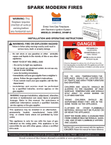
Fireplace size D x FW x RW
34" 18
1
/2" 34
3
/8" 14"
PRE-INSTALLATION
PREPARATION
LOCATION AND SPACE
REQUIREMENTS
Determine the safest and most efficient loca-
tion for your FMI direct-vent fireplace. Make
sure that rafters and wall studs are not in the
way of the venting system. Choose a loca-
tion where the heat output is not affected by
drafts, air conditioning ducts, windows or
doors. Figure 2 shows some common loca-
tions. Read all venting information in this
manual. Be aware of all restrictions and
precautions before deciding the exact loca-
tion for your fireplace.
When deciding the location of your fire-
place, follow these rules:
1. Do not connect this fireplace to a chim-
ney flue serving a separate solid-fuel
burning fireplace or appliance.
2. Due to high temperatures, do not lo-
cate this fireplace in high traffic areas
or near furniture or draperies.
3. Proper clearances must be maintained.
4. If your fireplace is to be installed di-
rectly on carpeting, vinyl tile, or any
combustible material other than wood,
it must be installed on a metal or wood
panel extending the full width and
depth of the fireplace. See Figure 3.
20"
34
"
5/8" for drywall facing
Must maintain a minimum
1" clearance to combustibles
34
3
/
4
"
34
1
/
4
"
20" Vertical Termination
19" Horizontal Termination
CLEARANCES
Minimum clearances to combustibles for
the fireplace are as follows:
Back, and sides 0"/mm
Perpendicular walls 6" (152mm)
Floor 0"/mm
Ceiling to louver opening 42" (1067mm)
Front 36" (914mm)
Top of Standoffs 0"/mm
See General Venting on pages 5 and 6 for
specific venting clearances.
FRAMING AND FINISHING
Figures 4 and 5 show typical framing of this
fireplace. Figure 6 on page 5 shows framing
for corner installation. All minimum clear-
ances must be met. Do not install fireplace
directly on carpeting, vinyl tile, or any com-
bustible material other than wood. The fire-
place must set on a metal or wood panel
extending the full width and depth of the
fireplace.
See Accessories on page 34 for mantel kits
available for this fireplace. If you are using a
separate combustible mantel piece, refer to
Figure 7 on page 5 for proper installation
height. You can install noncombustible man-
tels at any height above the fireplace.
Note:
Noncombustible mantels may discolor!
Figure 2 - Common Fireplace Locations
Figure 4 - Framing Clearances for Installation Against an Exterior Wall
Figure 5 - Framing Clearances for Typical
Fireplace Installation
Flush with a wall
Through exterior wall
enclosed in a chase
Corner
installation
Figure 3 - Fireplace Bottom Dimensions
D
RW
FW

5
107205
OWNER’S MANUAL
For more information, visit www.desatech.com
29"
13"
12
5
/
8
"
34
3
/
8
"
35
1
/
16
"
58"
9
1
/
4
"
41"
Nailing Tabs
PRE-INSTALLATION
PREPARATION
Continued
Figure 6 - Framing Clearances for Corner Installation
LOCATION OF VENT
TERMINATION
When locating vent termination, it is impor-
tant to observe the minimum clearances
shown in Figure 8, page 6. You will avoid
extra framing by positioning your fireplace
against an already existing framing mem-
ber. The sides of the fireplace may be posi-
tioned directly against combustible walls.
*Check with local codes or with the current
CAN/CGA B149 [.1 or .2] Installation Codes
for Canada or the USA Installations follow
the current National Fuel Gas Code, ANS
Z223.1, also known as NFPA 54.
These models are approved for use with
FMI 7" direct-vent pipe components and
terminations.
Your fireplace is approved to be vented either
through the side wall, or vertically using the
following guidelines:
• Only use FMI venting components or kits
specifically approved for this fireplace.
• Minimum clearance between vent pipes
and combustible materials is 1" (25 mm),
except where stated otherwise.
• Combustible material may be flush with
the top front of fireplace with a maxi-
mum thickness of 3/4".
• Do not recess venting terminals into a
wall or siding.
• If exterior wall is vinyl, you must use a
vinyl siding standoff.
• Install horizontal venting with a 1/4" rise
for every 12" of run toward the termination.
• You may paint the vent terminal with
450ºF (232ºC) heat-resistant paint to co-
ordinate with the exterior finish.
• There must not be any obstruction such
as bushes, garden sheds, fences, decks,
or utility buildings within 24" from the
front of the termination cap.
• Do not locate termination cap where exces-
sive snow or ice build up may occur. Be sure
to clear vent termination area after snow falls
to prevent accidental blockage of venting
system. When using snow blowers, do not
direct snow towards vent termination area.
GENERAL VENTING
C
B
A
D
E
F
G
Top of Louver Opening
3
2
1
4
5
6
7
Wall
Figure 7 - Clearances for Combustible Mantels
Ref. Mantel Depth Ref. Mantel from Top
of Louver Opening
1 14" (356mm) A 16" (406mm)
2 12" (305mm) B 14" (356mm)
3 10" (254mm) C 12" (305mm)
4 8" (203mm) D 10" (254mm)
5 6" (152mm) E 8" (203mm)
6 4" (101mm) F 6" (152mm)
7 2" (51mm) G 4" (101mm)
Continued
Note:
It is recom-
mended there be a
minimum clearance
of 18" above top of
louver opening when
installing a television
or entertainment
center above the
fireplace.

6
107205
DIRECT-VENT FIREPLACE
For more information, visit www.desatech.com
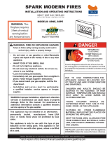
Figure 8 - Minimum Clearances for Vent Terminations
GENERAL VENTING
Continued
Fixed
Closed
Openable
Fixed
Closed
Openable
V
V
V
V
V
V
V
V
X
X
V
X
G
G
J
F
B
B
K
N
H
I
A
N
E
L
D
B
M
A
C
B
V
V
A
G
G
B
TERMINATION CAP
AIR SUPPLY INLET
GAS METER RESTRICTED AREA
(TERMINATION PROHIBITED)
A = clearance above grade, veranda, porch, deck, or balcony
[*12 inches (305mm) minimum]
B = clearance to window or door that may be opened
[12 inches (305mm) minimum]
C = clearance to permanently closed window [minimum 12 inches
(305mm) recommended to prevent condensation on window]
D = vertical clearance to ventilated soffit located above the terminal
within a horizontal distance of 24 inches (610mm) from the
center-line of the terminal [18 inches (457mm) minimum]
E = clearance to unventilated soffit [12 inches (305mm) minimum]
F = clearance to outside corner (see below)
G = clearance to inside corner (see below)
H = *not to be installed above a meter/regulator assembly within
36 inches (914mm) horizontally from the center-line of the regulator
I = clearance to service regulator vent outlet [*72 inches (1829mm)
minimum]
J = clearance to non-mechanical air supply inlet to building or the
combustion air inlet to any other fireplace [*12 inches (305mm)
minimum]
K = clearance to a mechanical air supply inlet [*72 inches (1829mm)
minimum]
L = † clearance above paved side-walk or a paved driveway located on
public property [*84 inches (2133mm) minimum]
M = clearance under veranda, porch, deck [*12 inches (305mm) minimum ‡]
N = clearance above a roof shall extend a minimum of 24 inches (610mm)
above the highest point when it passes through the roof surface and
any other obstruction within a horizontal distance of 18 inches (457mm)
† vent shall not terminate directly above a side-walk or paved driveway which is located between two
single family dwellings and serves both dwellings*
‡ only permitted if veranda, porch, deck or balconey is fully open on a minimum of 2 sides beneath the floor*
* as specified in CAN/SGA B149 (.1 or .2) Installation Codes (1991) for Canada or for U.S.A. installation follow
the current
National Fuel Gas Code, ANS Z223.1
Note: Local codes or regulations may require different clearances
A = 6" (152mm)
Inside Corner
V
B
E
V
B = 6" (152mm)
C = Maximum depth of 48" (1219mm) for
recessed location
D = Minimum width for back wall of
recessed location -
Combustible - 38" (965mm)
Noncombustible - 24" (610mm)
E = Clearance from corner in
recessed location-
Combustible - 6" (152mm)
Noncombustible - 2" (51mm)
Outside Corner Recessed Location
G
H
G = Combustible 24" (610mm)
Noncombustible 18" (457mm)
Balcony with No Side Wall
V
J
Combustible &
Noncombustible
H = 24" (610mm)
J = 20" (508mm)
Balcony with Perpendicular Side Wall
C
D
C
Termination Clearances for Buildings with Combustible and Noncombustible Exteriors

7
107205
OWNER’S MANUAL
For more information, visit www.desatech.com
WARNING: Read all instruc-
tions completely and thoroughly
before attempting installation. Fail-
ure to do so could result in serious
injury, property damage or loss of
life. Operation of improperly in-
stalled and maintained venting sys-
tem could result in serious injury,
property damage or loss of life.
WARNING: Seal all vent con-
nections. Seal only the outer pipe
connections with high temperature
silicone (600°F/316° C). Before join-
ing elbows and pipes, apply a bead
of high temperature silicone seal-
ant (GE RTV 106/Loctite RTV 81585)
to the male end of the elbow or
pipe. High temperature silicone
must also be used to re-seal any
connections after maintenance to
venting system.
NOTICE: Failure to follow these
instructions will void the warranty.
INSTALLATION PRECAUTIONS
Consult local building codes before begin-
ning the installation. The installer must make
sure to select the proper vent system for
installation. Before installing vent kit, the
installer must read this fireplace manual and
vent kit instructions.
Only a qualified service person should in-
stall venting system. The installer must fol-
low these safety rules:
• Wear gloves and safety glasses for
protection
• Use extreme caution when using ladders
or when on roof tops
• Be aware of electrical wiring locations
in walls and ceilings
The following actions will void the war-
ranty on your venting system:
• Installation of any damaged venting
component
• Unauthorized modification of the vent-
ing system
VENTING
INSTALLATION
WARNING: This gas fireplace
and vent assembly must be
vented directly to the outside.
The venting system must NEVER
be attached to a chimney serving
a separate solid fuel burning ap-
pliance. Each gas appliance must
use a separate vent system. Do
not use common vent systems.
WARNING: Horizontal sec-
tions of this vent system require a
minimum clearance of 2" from the
top of the pipe and 1" minimum to
the sides and bottom. 1
1
/2" clear-
ance is required where termina-
tion penetrates a combustible wall.
Vertical sections of this system
require a minimum of 1" clear-
ance to combustible materials on
all sides of the pipe.
• Installation of any component part not
manufactured or approved by DESA
International
• Installation other than as instructed by
these instructions
INSTALLATION PLANNING
There are two basic types of direct-vent
installation:
• Horizontal Termination
• Vertical Termination
It is important to select the proper length of
vent pipe for the type of termination you
choose. It is also important to note the wall
thickness.
For Horizontal Termination: Select the
amount of vertical rise desired. The horizon-
tal run of venting must have 1/4" rise for
every 12" of run towards the termination.
NOTICE: Treatment of firestops
and construction of the chase may
vary from building type to building
type. These instructions are not
substitutes for the requirements
of local building codes. You must
follow all local building codes .
Note:
When installing in a chase, you should
insulate the chase as you would the outside
walls of your home. This is especially im-
portant in cold climates. Minimum clear-
ance between vent pipes and combustible
materials such as insulation is 1".
After framing the chase (see Framing and
Finishing on page 4) install the vent system
by following the installation instructions.
Installing Vent System in a Chase
A chase is a vertical boxlike structure built
to enclose venting that runs along the out-
side of a building. A chase is not required for
such venting.
Continued
WARNING: Never run the vent
downward as this may cause ex-
cessive temperatures which
could cause a fire.
You may use one or two 90° elbows in this
vent configuration. See Horizontal Termina-
tion Configurations on pages 10 and 11.
For Vertical Termination: Measure the dis-
tance from the fireplace flue outlet to the
ceiling. Add the ceiling thickness, the verti-
cal rise in an attic or second story, and allow
for sufficient vent height above the roofline.
You may use one or two 90° elbows in this
vent configuration. See Vertical Termination
Configurations on pages 13 and 14.
Note:
You may use two 45° elbows in place
of a 90° elbow. You must follow rise to run
ratios when using 45° elbows.
For two-story applications, firestops are re-
quired at each floor level. If an offset is
needed in the attic, additional pipe and el-
bows will be required.
You may use a chase with a vent termination
with exposed pipe on the exterior of the house.
See Installing Vent System in a Chase, below.
Your FMI direct-vent fireplace has been tested
for a minimum 3' rise with a maximum 10"
wall thickness. The maximum horizontal run
is 20' with 8' vertical rise (see Installation for
Horizontal Termination, page 8). The maxi-
mum vertical run is 30' (see Installation for
Vertical Termination, page 12).
It is very important that the venting system
maintain its balance between the combus-
tion air intake and the flue gas exhaust.
Certain limitations apply to vent configura-
tions and must be strictly followed.

8
107205
DIRECT-VENT FIREPLACE
For more information, visit www.desatech.com
INSTALLATION FOR
HORIZONTAL TERMINATION
1. Determine the route your horizontal
venting will take.
Note:
The location
of the horizontal vent termination on the
exterior wall must meet all local and
national building codes and must not be
easily blocked or obstructed.
Snorkel terminations are available for
terminations requiring a vertical rise on
the exterior of the building (see Figures
9 and 10). Follow the same installation
procedures as used for standard horizon-
tal terminations. If installing the snor-
kel termination below grade (basement
applications), you must provide proper
drainage to prevent water from entering
the snorkel termination (see Figure 10).
Do not back fill around the snorkel ter-
mination.
2. Rigid vent pipes and fittings have spe-
cial twist-lock connections. Assemble
the desired combination of pipe and el-
bows to the appliance adaptor with pipe
seams oriented towards the wall or floor.
Twist-lock Procedure: The female
ends of the pipes and fittings have four
locking lugs (indentations). These lugs
will slide straight into matching slots on
the male ends of adjacent pipes and fit-
tings. (All connections must be sealed
with high temperature silicone sealant
as specified in the second warning state-
ment on page 7.) Push the pipe sections
together and twist one section clockwise
approximately one-quarter turn until the
sections are fully locked. See Figure 11,
page 9.
Note:
Horizontal runs of vent
must be supported every three feet. Use
wall straps for this purpose.
VENTING
INSTALLATION
Continued
WARNING: Do not recess vent
terminal into a wall or siding.
Figure 10 - Snorkel Termination with Drainage Pipe
12" Minimum
Figure 9 - Snorkel Termination
Snorkel
12" Minimum
Snorkel
Adequate
Drainage

9
107205
OWNER’S MANUAL
For more information, visit www.desatech.com
VENTING
INSTALLATION
Continued
(Framing
Detail)
10"
(254mm)
10"
(254mm)
7
1
/
2
"
(190mm)
Vent Opening
Combustible Wall
Vent Opening
Noncombustible Wall
Figure 12 - Vent Opening Requirements
Continued
3. Attach vent pipe assembly to the fire-
place. Set fireplace in front of it’s perma-
nent location to insure minimum clear-
ances. See page 10, Figure 16 for mini-
mum clearances for vertical on rigid
vent pipe, and page 10 Figure 17 on
flexible vent pipe. Mark the wall for a
10" square hole (for noncombustible ma-
terial such as masonry block or concrete,
a 7
1
/2" diameter hole is acceptable). See
Figure 12. The center of the hole should
line up with the center-line of the hori-
zontal rigid vent pipe. Cut a 10"x10"
(254mm x 254mm) square hole through
combustible exterior wall (7
1
/2" [190mm]
diameter hole if noncombustible). Frame
as necessary (see Figure 12).
UP
Figure 14 - Installing Vinyl Siding Standoff
Cut Vinyl Siding
Away to Fit
Standoff
Wood Screw
Nut
Bolt
Standoff
Vent Cap
Figure 11 - Rigid Vent Pipe Connections
Female
Locking
Lugs
Male
Slots
Apply Mastic
to All Four Sides
Figure 13 - Installing Horizontal Vent Cap
UP
Wood
Screw
Vent Cap
Apply Mastic
to All Four
Sides
WARNING: Do not recess vent
termination in to any wall. This
will cause a fire hazard.
4. Apply a bead of non-hardening mastic
around the outside edge of the vent cap.
Position the vent cap in the center of
the 7
1
/2" or 10" hole on the exterior
wall with the arrow on the vent cap
pointing up. Insure proper clearance of
1" to combustibles is maintained. At-
tach the vent cap with four wood screws
supplied (see Figure 13).
Note
: Re-
place the wood screws with appropri-
ate fasteners for stucco, brick, concrete,
or other types of siding.
5. For vinyl siding use vinyl siding stand-
offs between vent cap and exterior wall.
The vinyl siding standoff prevents ex-
cessive heat from melting the vinyl sid-
ing material. Bolt the vent cap to the
standoff. Apply non-hardening mastic
around outside edge of the standoff in-
stead of the vent cap assembly. Use
wood screws provided to attach the
standoff. See Figure 14.
6. Slide the wall thimble over the vent
pipe before connecting the horizontal
run to the vent cap (see Figure 15).
7. Carefully move the fireplace with vent
assembly attached toward the wall and
insert the vent pipe into the horizontal
termination. The pipe overlap should
be a minimum of 1
1
/4". Apply silicone
to the outer pipe connection. Fasten all
vent connections with screws provided.
Refer to Fireplace Installation on page
16 for instructions on securing unit to
framing or floor.
8. Slide the wall thimble against the inte-
rior wall surface and attach with screws
provided (see Figure 15).
Vent Cap
(Horizontal
Termination)
Interior Wall
Surface
Wall
Thimble
Horizontal
Vent Pipe
Figure 15 - Connecting Vent Cap with
Horizontal Vent Pipe
Screw

10
107205
DIRECT-VENT FIREPLACE
For more information, visit www.desatech.com
VENTING
INSTALLATION
Continued
UP
UP
Rigid Vent Pipe
Horizontal Venting
Vertical (V) Horizontal (H)
37" min. 10" max.
Figure 16 - Horizontal Termination Configuration for Rigid Venting
Figure 17 - Horizontal Termination Configuration for Rigid Venting Using One
90
°
Elbow
Flexible Vent Pipe
Horizontal Venting
Vertical (V) Horizontal (H)
44" min. 29" max.
(30° and 90° only, no vertical pipe)
55" min. 41" max.
(30° elbow, 1' vertical pipe, 90° elbow)
67" min. 60" max.
79" min. 84" max.
96" min. 20' max.
Note:
This configuration for use with
corner installation.
Rigid Vent Pipe Horizontal
Termination Configurations
Figures 16 through 19 show different con-
figurations for venting with horizontal ter-
mination. Each figure includes a chart with
vertical minimum/maximum and horizon-
tal maximum dimensions which must be
met. Seal all connections with high tem-
perature silicone sealant (outer pipe only) as
specified in the second warning statement
on page 7. All horizontal terminations re-
quire 1/4" rise per 12" of horizontal run.
FD60
60˚ Starter/
Adapter Required
FD30
30˚ Starter/
Adapter Required
*
*
* Note: Remember to add 1/
4” rise per 12” horizontal
length of pipe.

11
107205
OWNER’S MANUAL
For more information, visit www.desatech.com
VENTING
INSTALLATION
Continued
UP
Venting with Two 90° Elbows
Vertical (V) Horizontal (H
1
) Horizontal (H
1
) +
Horizontal (H
2
)
5' min. 2' max. 6' max.
6' min. 4' max. 12' max.
7' min. 6' max. 18' max.
8' min. 8' min. 20' max.
20' max. 8' max. 20' max.
Venting with Two 90° Elbows
Vertical (V) Horizontal (H
1
) +
Horizontal (H
2
)
5' min. 6' max.
6' min. 12' max.
7' min. 18' max.
8' min. 20' max.
20' max. 20' max.
Figure 18 - Horizontal Termination Configuration for Rigid Venting Using Two 90
°
Elbows
Figure 19 - Horizontal Termination Configuration for Rigid Venting Using Two 90
°
Elbows with Termination at 90
°
with Fireplace
Continued
FD60
60˚ Starter/
Adapter Required
FD30
30˚ Starter/
Adapter Required
*
*
* Note: Remember to add 1/
4” rise per 12” horizontal
length of pipe.

12
107205
DIRECT-VENT FIREPLACE
For more information, visit www.desatech.com
4. Connect a section of pipe and extend
up through the hole.
Note:
If an offset is needed to avoid
obstructions, you must support the vent
pipe every 3 feet. Use wall straps for
this purpose (see Figure 20). Whenever
possible, use 45° elbows instead of 90°
elbows. The 45° elbow offers less re-
striction to the flow of the flue gases
and intake air.
5. Place the flashing over the pipe
section(s) extending through the roof.
Secure the base of the flashing to the
roof and framing with roofing nails. Be
sure roofing material overlaps the top
edge of the flashing as shown in Figure
20. There must be a 1" clearance from
the vent pipe to combustible materials.
6. Continue to add pipe sections until the
height of the vent cap meets the mini-
mum building code requirements de-
scribed in Figure 8 on page 6.
Note
: You
must increase vent height for steep roof
pitches. Nearby trees, adjoining rooflines,
steep pitched roofs, and other similar fac-
tors may cause poor draft or down-draft-
ing in high winds. Increasing the vent
height may solve this problem.
7. Twist-lock the vent cap onto the last
section of vent pipe and seal outer pipe
connection with high temperature sili-
cone sealant as specified in the second
warning statement on page 7.
Note:
If the vent pipe passes through any
occupied areas above the first floor, including
storage spaces and closets, you must enclose
pipe. You may frame and sheetrock the enclo-
sure with standard construction material. Make
sure and meet the minimum allowable clear-
ances to combustibles. Do not fill any of the
required air spaces with insulation.
Cathedral Ceiling Installation
1. Remove shingles or other roof cover-
ing as necessary to cut the rectangular
hole for the support box. Mark the out-
line of the cathedral ceiling support box
on the roof sheathing using the locat-
ing hole as a center point.
2. Cut the hole 1/8" larger than the sup-
port box outline (see Figure 22, page 13).
INSTALLATION FOR
VERTICAL TERMINATION
1. Determine the route your vertical vent-
ing will take. If ceiling joists, roof
rafters, or other framing will obstruct
the venting system, consider an offset
(see Figure 20) to avoid cutting load
bearing members.
Note:
Pay special
attention to these installation instruc-
tions for required clearances (air space)
to combustibles when passing through
ceilings, walls, roofs, enclosures, attic
rafters, etc. Do not pack air spaces with
insulation. Also note maximum verti-
cal rise of the venting system and any
maximum horizontal offset limitations.
Offsets must fall within the parameters
shown in Figure 8 on page 6.
2. Set the fireplace in desired location.
Drop a plumb line down from the ceil-
ing to the position of the fireplace exit
flue. Mark the center point where the
vent will penetrate the ceiling. Drill a
small locating hole at this point.
Drop a plumb line from the inside of
the roof to the locating hole in the ceil-
ing. Mark the center point where the
vent will penetrate the roof. Drill a
small locating hole at this point.
Flat Ceiling Installation
1. Cut a 10" square hole in the ceiling us-
ing the locating hole as a center point.
The opening should be framed to
10"x10" (254mm x 254mm) inside di-
mensions, as shown in Figure 12 on
page 9 using framing lumber the same
size as the ceiling joists. If the area
above the ceiling is an insulated ceil-
ing or a room, nail firestop from the
top side. This prevents loose insulation
from falling into the required clearance
space. Otherwise, install firestop below
the framed hole. The firestop should be
installed with no less than three nails
per side (see Figure 21).
2. Assemble the desired lengths of pipe
and elbows necessary to reach from the
fireplace flue up through the firestop.
All connections must be sealed with
high temperature silicone sealant as
specified in the second warning state-
ment on page 7. Be sure all pipe and
elbow connections are fully twist-
locked (see Figure 11, page 9).
3. Cut a hole in the roof using the locating
hole as a center point. (Cover any ex-
posed open vent pipes before cutting
hole in roof.) The 10"x10" hole must
be measured on the horizontal; actual
length may be larger depending on the
pitch of the roof. There must be a 1"
clearance from the vent pipe to combus-
tible materials. Frame the opening as
shown in Figure 12 on page 9.
VENTING
INSTALLATION
Continued
Figure 20 - Offset with Wall Strap and 45
°
Elbows
45° Elbow
Wall Strap
Roof
Flashing
Ceiling Firestop
Figure 21 - Installing Firestop
If area above is not a room, install
firestop below framed hole.
If area above is a room, install firestop
above framed hole.

13
107205
OWNER’S MANUAL
For more information, visit www.desatech.com
VENTING
INSTALLATION
Continued
Continued
Figure 22 - Cathedral Ceiling Support
Box Installation
Non-hardening Mastic under all
edges of support box before nailing
Figure 23 - Installed Cathedral Ceiling
Support Box
Vertical Termination Configurations
Figures 24 through 27 show four different configurations for vertical termination. All
connections must be sealed with high temperature silicone sealant as specified in the second
warning statement on page 7.
Venting with Two 90° Elbows
Vertical (V) Horizontal (H
1
) +
Horizontal (H
2
)
5' min. 2' max.
6' min. 4' max.
7' min. 6' max.
8' min. 8' max.
20' max. 8' max.
Figure 24 - Vertical Rigid Venting Configuration Using Two 90
°
Elbows with Two
Horizontal Runs
3. Lower the support box through the hole
in the roof until the bottom of the box
extends at least 2" below the ceiling
(see Figure 22). Align the support box
vertically and horizontally using a
level. Temporarily tack the support box
in place through the inside walls and
into the roof sheathing.
4. Using tin snips, cut the support box from
the top corners down to the roofline and
fold the resulting flaps over the roof
sheathing (see Figure 23). Apply a bead
of non-hardening mastic around the top
edges of the support box to make a seal
between the box and the roof. Nail in
place with roofing nails. Remove any
combustible material that might be in-
side of the support box.
5. Complete the cathedral ceiling instal-
lation by following the same proce-
dures outlined in steps 2 through 7 for
Flat Ceiling Installation, page 12
.
Venting with One 90° Elbow
Vertical (V) Horizontal (H)
5' min. 2' max.
6' min. 4' max.
7' min. 6' max.
8' min. 8' max.
20' max. 8' max.
Figure 25 - Vertical Rigid Venting Configuration Using One 90
°
Elbow
Cut hole 1/8" larger than support
box when projected onto roofline
2" minimum below
finished ceiling
Cathedral ceiling
support box
Level
Note:
Restrictor must be
installed in all vertical
installations.
Note:
Restrictor must be
installed in all vertical
installations.
FD60
60˚ Starter/
Adapter Required
FD60
60˚ Starter/
Adapter
Required

14
107205
DIRECT-VENT FIREPLACE
For more information, visit www.desatech.com
Vertical Venting
V = 40' max.
Figure 27 - Vertical Rigid Venting
Configuration With No Horizontal Run
VENTING
INSTALLATION
Continued
Venting with Two 90° Elbows
Vertical (V
1
) Horizontal (H)
5' min. 6' max.
6' min. 12' max.
7' min. 18' max.
8' min. 20' max.
Note:
Vertical (V
1
) +
Vertical (V
2
) = 20' max.
Figure 26 - Vertical Rigid Venting Configuration Using Two 90
°
Elbows
Note:
Restrictor must be
installed in all vertical
installations.
FD30
30˚ Starter/
Adapter
Required
FD30
30˚ Starter/
Adapter
Required

15
107205
OWNER’S MANUAL
For more information, visit www.desatech.com
VENTING
INSTALLATION
Continued
HIGH ALTITUDE
INSTALLATION
Your FMI direct-vent fireplace has been
AGA tested and approved for elevations
from 0-2000 feet and CGA certified for
elevations from 0-4500 feet.
When installing this fireplace at an elevation
above 2000 feet (in the USA), you may need
to decrease the input rating by changing the
existing burner orifice to a smaller size. Re-
duce input 4% for each 1000 feet above sea
level. Check with your local gas company for
proper orifice size identification.
When installing this fireplace at an eleva-
tion above 4500 feet (in Canada), check
with local authorities.
Consult your local gas company to help de-
termine the proper orifice for your location.
For assistance with any high altitude installa-
tion contact DESA International’s Technical
Service Department at 1-800-DESA-LOG
(1-800-337-2564).
PARTS LISTS FOR VENTING
KITS AND COMPONENTS
FMI Rigid Venting
Number Description
FD30 30˚ Starter/Adapter (6 5/8" to 7")
6 per box
FD60 60˚ Starter/Adaptor (6 5/8" to 7")
6 per box
F7030 7" to 12" Adjustable pipe length
6 per box
D1031 7” to 12” Adjustable pipe length
1 per box
D3050 Vertical restrictor
6 per box
01806 Basic vertical kit
Adjustable flashing - storm collar,
vertical cap
01807 48" Pipe length
6 per box
01808 36" Pipe length
6 per box
01809 24" Pipe length
6 per box
01810 12" Pipe length
6 per box
01811 6" Pipe length
6 per box
01812 17" to 24" adjustable pipe length
6 per box
01813 45˚ Elbow
6 per box
01814 90˚ Elbow
6 per box
01817 Wall firestop
6 per box
01818 Adjustable flashing (0/12-8/12)
6 per box
01819 Steep pitch flashing (12/12)
6 per box
01820 Vinyl/Stucco siding standoff
01821 Firestop plate
6 per box
01822 Vertical termination cap
01823 Horizontal round termination
cap
Number Description
01825 36" Snorkel termination
01826 14" Snorkel termination
01827 Termination/high
rise/horizontal
01828 Wall strap
6 per box
01829 Storm collar
6 per box
01797 Vertical round high wind
termination
01799 Horizontal square high wind
termination

16
107205
DIRECT-VENT FIREPLACE
For more information, visit www.desatech.com
INSTALLING OPTIONAL
BLOWER ACCESSORY
IMPORTANT
: For clarity, gas valve assem-
bly and grate/burner assembly are not shown
in Figures 29 through 32, page 17. They will,
however, be in your fireplace when you are
installing the blower. Also for clarity the
firebox is shown with dotted lines.
1. Open lower louver panel or remove for
easier access.
2. Place the blower against the lower rear
wall of firebox outer wrapper with the
exhaust port directed upward. Align the
holes in the top mounting tabs of
blower with holes in wall of wrapper
(see Figure 29, page 17). Using the two
screws provided, mount blower and
tighten screws securely.
Note:
For DA3610TA, make sure the
thermal switch is comfortably under the
back of the firebox as shown in Figure
30, page 17.
3. Be sure to securely attach all wire ter-
minals to terminals on blower motor
(and thermal switch where applicable)
and that the screw retaining the green
ground wire is tight.
4. Remove screws securing the plate to
the bottom of the firebox and set aside.
5. Place speed control against back of this
plate and push the plastic control shaft
through opening (see Figure 31, page 17).
6. While supporting speed control, secure
control shaft with lock nut by pushing and
turning lock nut with pliers clockwise
until tight against the plate. Place control
knob provided onto shaft (see Figure 31,
page 17).
7. Replace plate containing switch and
tighten screws securely.
NOTICE: If installing blower in an
existing fireplace with gas con-
nections, shut off gas supply and
disconnect heater from gas sup-
ply. Contact a qualified service
person to do this.
CHECK GAS TYPE
Use proper gas type for the fireplace unit
you are installing. If you have conflicting
gas types, do not install fireplace. See re-
tailer where you purchased the fireplace for
proper fireplace according to your gas type.
FIREPLACE
INSTALLATION
NOTICE: This fireplace is in-
tended for use as supplemental
heat. Use this fireplace along with
your primary heating system. Do
not install this fireplace as your
primary heat source. If you have
a central heating system, you may
run system’s circulating blower
while using fireplace. This will
help circulate the heat through-
out the house. In the event of a
power outage, you can use this
fireplace as a heat source.
WARNING: A qualified installer
or service person must install fire-
place. Follow all local codes.
CAUTION: This fireplace cre-
ates warm air currents. These cur-
rents move heat to wall surfaces
next to fireplace. Installing fire-
place next to vinyl or cloth wall
coverings or operating fireplace
where impurities (such as to-
bacco smoke, aromatic candles,
cleaning fluids, oil or kerosene
lamps, etc.) in the air exist, may
discolor walls.
Note:
Your fireplace is designed to be used
in zero clearance installations. Wall or fram-
ing material can be placed directly against
any exterior surface on the rear, sides, or top
of your fireplace, except where standoff
spacers are integrally attached. If standoff
spacers are attached to your fireplace, these
spacers can be placed directly against wall
or framing material. See framing details on
page 4.
Place the fireplace into position and shim
with noncombustible material if needed.
Nail the side flanges to the framing to secure
the unit in place. There are two floor brack-
ets included with each unit. Use these as an
alternative method of securing the fireplace.
IMPORTANT:
Make sure fireplace is level
before securing. If fireplace is not level it
will not work properly.
Attaching Thermal Switch to
DA3610TA Thermostatically-
Controlled Blower
When installing the DA3610TA thermo-
statically-controlled blower accessory, you
must first secure the thermal switch to the
blower.
1. Remove the two hex head screws on the
blower assembly as shown in Figure 28.
2. Place the green wire between the bot-
tom hole on the thermal switch bracket
and the bottom hole on the blower as-
sembly. Insert one of the hex screws
into all three pieces and tighten.
3. Insert the top screw through the ther-
mal switch bracket and into the blower
assembly. Tighten screw.
4. Connect the blue wire on the blower
assembly to the right side of the ther-
mal switch.
5. Connect the black wire to the left side
of the thermal switch.
Installing GA3700/DA3610TA
Blowers
Figure 28 - Attaching Thermal Switch to DA3610TA Thermostatically-Controlled
Blower Accessory
Blower Assembly
Blue Wire
Green Wire
Black Wire
White Wire
Hex Head
Screws
Thermal Switch
with Bracket

17
107205
OWNER’S MANUAL
For more information, visit www.desatech.com
FIREPLACE
INSTALLATION
Continued
WARNING: Never touch the
blower wheel while in operation.
10. Peel off the backing paper and stick the
supplied wiring diagram decal on the
firebox bottom approximately 3" to the
right of the blower speed control
bracket (Figure 32).
WARNING: Failure to position
the parts in accordance with sup-
plied diagrams or failure to use
only parts specifically approved
with this heater may result in dam-
age or personal injury.
11. Connect or reconnect gas supply to fire-
place per Connecting Fireplace to Gas
Supply on page 19 of this manual.
8. Plug in blower power cord.
a. If your fireplace system is installed
as a freestanding unit with an ac-
cessory mantel, determine whether
the power cord will exit the left side
or the right side of the firebox. In-
stall one plastic bushing provided
into the 1
1
/2" hole in the outer cas-
ing through which the power cord
will exit. Install the second plastic
bushing provided into the floor sup-
port bracket if exiting through the
right side (see Figure 32). Route
power cord through (both) plastic
bushing(s) and plug the power cord
into a properly grounded 3-prong
wall receptacle near the firebox.
b.If your fireplace system installation
is recessed and/or pre-wired, a
qualified installer must make all elec-
trical connections for the outlet kit
included with the fireplace.
WARNING: A qualified ser-
vice person must connect fire-
place to gas supply. Follow all
local codes.
Figure 31 - Attaching Speed Control to
Firebox
Figure 32 - Installing Plastic Bushing and
Wiring Diagram Sticker
Continued
9. Check to make sure that the power cord
is completely clear of the blower wheel
and that there are no other foreign ob-
jects in blower wheel. Turn blower on
and check for operation. Turn blower
off by rotating knob fully counterclock-
wise before continuing.
Plastic Bushing
Wiring
Diagram
Blower Speed
Control Bracket
Figure 30 - Locating Thermal Switch Against Back of Firebox
Thermal Switch
Side View
Firebox Bottom
Firebox Back
Firebox Flange
Blower
Thermal
Switch
Thermal
Switch
Bracket
Control
Knob
Locknut
Control Shaft
Speed
Control
Figure 29 - Mounting Blower to Firebox
Top
Mounting
Tab
Exhaust Port
Blower
Screws
Lower Louver
Panel
Lower Rear
Wall of
Firebox
Wrapper

18
107205
DIRECT-VENT FIREPLACE
For more information, visit www.desatech.com
Figure 34 - Gas Connection
* The CSA design-certified equipment shutoff valve may be supplied with the appliance
or you can purchase it from your retailer.
CAUTION: Use only new,
black iron or steel pipe. Inter-
nally-tinned copper tubing may
be used in certain areas. Check
your local codes. Use pipe of 1/2"
diameter or greater to allow
proper gas volume to fireplace. If
pipe is too small, undue loss of
pressure will occur.
Installation must include an equipment
shutoff valve, union, and plugged 1/8" NPT
tap. Locate NPT tap within reach for test
gauge hook up. NPT tap must be upstream
from fireplace (see Figure 34).
For propane/LP connections only, the in-
staller must supply an external regulator.
The external regulator will reduce incoming
gas pressure. You must reduce incoming
gas pressure to between 11 and 14 inches of
water. If you do not reduce incoming gas
pressure, heater regulator damage could
occur. Install external regulator with the
vent pointing down as shown in Figure 33.
Pointing the vent down protects it from
freezing rain or sleet.
FIREPLACE
INSTALLATION
Continued
INSTALLING GAS PIPING TO
FIREPLACE LOCATION
Installation Items Needed
Before installing fireplace, make sure you
have the items listed below.
• external regulator (supplied by installer)
• piping (check local codes)
• sealant (resistant to propane/LP gas)
• equipment shutoff valve *
• test gauge connection *
• sediment trap
• tee joint
• pipe wrench
• approved flexible gas line with gas con-
nector (if allowed by local codes) (not
provided)
* A CSA design-certified equipment shutoff
valve with 1/8" NPT tap is an acceptable
alternative to test gauge connection. Pur-
chase the CSA design-certified equipment
shutoff valve from your retailer.
WARNING: A qualified ser-
vice person must connect fire-
place to gas supply. Follow all
local codes.
CAUTION: For propane/LP
units, never connect heater di-
rectly to the propane/LP supply.
This heater requires an external
regulator (not supplied). Install the
external regulator between the
heater and propane/LP supply.
CAUTION: Use pipe joint seal-
ant that is resistant to liquid pe-
troleum (LP) gas.
Figure 33 - External Regulator with Vent
Pointing Down (Propane/LP Only)
Propane/
LP Supply
Tank
External
Regulator
Vent
Pointing
Down
We recommend that you install a sediment
trap/drip leg in supply line as shown in
Figure 34. Locate sediment trap/drip leg
where it is within reach for cleaning. Install
in piping system between fuel supply and
heater. Locate sediment trap/drip leg where
trapped matter is not likely to freeze. A
sediment trap traps moisture and contami-
nants. This keeps them from going into
fireplace gas controls. If sediment trap/drip
leg is not installed or is installed wrong,
fireplace may not run properly.
IMPORTANT:
Install equipment shutoff
valve in an accessible location. The equip-
ment shutoff valve is for turning on or
shutting off the gas to the appliance.
Check your building codes for any special
requirements for locating equipment shutoff
valve to fireplaces.
Apply pipe joint sealant lightly to male
threads. This will prevent excess sealant
from going into pipe. Excess sealant in pipe
could result in clogged fireplace valves.
CSA Design-Certified
Equipment Shutoff Valve
with 1/8" NPT Tap*
3" Minimum
Propane/LP - From
External Regulator (11"
W.C. to 14" W.C.
Pressure)
Approved Flexible
Gas Line
Cap Pipe Nipple Tee Joint
Sediment Trap/Drip Leg
Natural - From Gas
Meter (5" W.C. to 10.5"
W.C. Pressure )

19
107205
OWNER’S MANUAL
For more information, visit www.desatech.com
Pressure Testing Gas Supply
Piping System
Test Pressures In Excess Of 1/2 PSIG
(3.5 kPa)
1.
Disconnect appliance with its appliance
main gas valve (control valve) and
equipment shutoff valve from gas
supply piping system. Pressures in
excess of 1/2 psig (3.5 kPa) will damage
fireplace gas regulator.
2. Cap off open end of gas pipe where
equipment shutoff valve was con-
nected.
3. Pressurize supply piping system by ei-
ther opening propane/LP supply tank
valve for propane/LP gas fireplace or
opening main gas valve located on or near
gas meter for natural gas fireplace,
or
using compressed air.
4. Check all joints of gas supply piping
system. Apply commercial leak test so-
lution to all gas joints. Bubbles forming
show a leak. Correct all leaks at once.
5. Reconnect fireplace and equipment
shutoff valve to gas supply. Check re-
connected fittings for leaks.
CHECKING GAS
CONNECTIONS
WARNING: Test all gas pip-
ing and connections for leaks
after installing or servicing. Cor-
rect all leaks at once.
WARNING: Never use an open
flame to check for a leak. Apply
commercial leak test solution to
all gas joints. Bubbles forming
show a leak. Correct all leaks at
once.
Installation Items Needed
• 5/16" hex socket wrench or nut-driver
• sealant (resistant to propane/LP gas, not
provided)
1. Open lower louver door panel by gen-
tly pulling forward.
2. Route flexible gas supply line through
one of the access holes on side of fire-
place.
3. Attach flexible gas line from gas sup-
ply (see Figure 35) to fireplace gas
valve.
4. Check all gas connections for leaks. See
Checking Gas Connections, pages 19
and 20.
CONNECTING FIREPLACE
TO GAS SUPPLY
FIREPLACE
INSTALLATION
Continued
To Gas Supply
(Natural)
To External Regulator
(Propane/LP)
Flexible Gas Line from
Equipment Shutoff Valve
Provided by Installer
Figure 35 - Attaching Flexible Gas Line to Control Valve
Continued
Equipment Shutoff
Valve
Control Valve

20
107205
DIRECT-VENT FIREPLACE
For more information, visit www.desatech.com
FIREPLACE
INSTALLATION
Continued
Test Pressures Equal To or Less Than
1/2 PSIG (3.5 kPa)
1. Close equipment shutoff valve (see Fig-
ure 36).
2. Pressurize supply piping system by ei-
ther opening propane/LP supply tank
valve for propane/LP gas fireplace or
opening main gas valve located on or near
gas meter for natural gas fireplace,
or
using compressed air.
3. Check all joints from propane/LP sup-
ply tank or gas meter to equipment
shutoff valve (see Figure 37 for pro-
pane/LP or Figure 38 for natural). Ap-
ply commercial leak test solution to all
gas joints. Bubbles forming show a
leak. Correct all leaks at once.
Pressure Testing Fireplace Gas
Connections
1. Open equipment shutoff valve (see Fig-
ure 36).
2. Open propane/LP supply tank valve for
propane/LP fireplace or main gas valve
located on or near gas meter for natu-
ral gas fireplace.
3. Make sure control knob of fireplace is
in the OFF position.
4. Check all joints from equipment shutoff
valve to thermostat gas valve (see Fig-
ure 37 for propane/LP or Figure 38 for
natural). Apply commercial leak test so-
lution to all gas joints. Bubbles forming
show a leak. Correct all leaks at once.
5. Light fireplace (see Operating Fire-
place, pages 24 and 25). Check all other
internal joints for leaks.
6. Turn off fireplace (see To Turn Off Gas
to Appliance, page 24).
Figure 36 - Equipment Shutoff Valve
ON
POSITION
OFF
POSITION
Open
Closed
Equipment
Shutoff
Valve
Figure 38 - Checking Gas Joints for Natural Gas Fireplace
Figure 37 - Checking Gas Joints for Propane/LP Gas Fireplace
Gas Meter
Gas Valve
Equipment
Shutoff
Valve
Propane/LP Supply Tank
Gas Valve
Equipment
Shutoff
Valve
/