Page is loading ...

RW30
ROBOTIC
WELDER
Copyright
©
The Stanley Works 2014
69893 8/2014 ver 7
USER'S MANUAL
Safety, Operation and Maintenance
RW30
ROBOTIC
WELDER
Copyright
©
The Stanley Works 2014
69893 8/2014 ver 7
USER'S MANUAL
Safety, Operation and Maintenance

2 - RW30 USER MANUAL
SERIOUS INJURY OR DEATH COULD RESULT FROM THE
IMPROPER REPAIR OR SERVICE OF THIS TOOL.
REPAIRS AND / OR SERVICE TO THIS TOOL MUST ONLY BE DONE BY AN AUTHORIZED AND CERTIFIED
DEALER.
MAKE NO ALTERATIONS OR MODIFICATIONS TO THE TOOL.
SERIOUS INJURY COULD RESULT FROM IMPROPER CHANGES.
MODIFICATIONS OR ALTERATIONS COULD ALTER THE PERFORMANCE OR INTEGRITY OF THE TOOL.
To ll out a Product Warranty Recording form, and for information on your warranty, visit
Stanleyhydraulics.com and select the Company tab, Warranty.
(NOTE: The warranty recording form must be submitted to validate the warranty).
IMPORTANT
GENERAL INFORMATION

RW30 USER MANUAL - 3
SERVICING: This manual contains safety, operation, and routine maintenance instructions. Stanley Hydraulic
Tools recommends that servicing of hydraulic tools, other than routine maintenance, must be performed by an
authorized and certied dealer. Please read the following warning.
SAFETY SYMBOLS ................................................................................................................................................................................ 5
LOCAL SAFETY REGULATIONS ........................................................................................................................................................... 5
SAFETY PRECAUTIONS ........................................................................................................................................................................ 6
OPERATION .......................................................................................................................................................................................... 11
OVERVIEW ........................................................................................................................................................................................ 11
PREPARING THE RW30 FOR OPERATION .................................................................................................................................... 11
CLAW VERSION ............................................................................................................................................................................... 11
CLAMP VERSION ............................................................................................................................................................................. 12
CONNECTING THE WIRE FEED/WELDING TIP TO THE RW30 .................................................................................................... 13
SETTING THE STICK OUT ............................................................................................................................................................... 13
OPERATING THE RW30 & THE CHARLIE CONTROL UNIT ........................................................................................................... 14
INFORMATION ON DATA TRACKING .............................................................................................................................................. 16
MANUAL DATA ENTRY ..................................................................................................................................................................... 16
AUTOMATIC DATA ENTRY ............................................................................................................................................................... 16
OPERATOR DIALOGUE ...................................................................................................................................................................17
STOP AND RESTART OF WELDING CYCLE ................................................................................................................................... 20
ERROR MESSAGES ......................................................................................................................................................................... 20
EQUIPMENT MAINTENANCE & CARE ................................................................................................................................................ 22
TROUBLESHOOTING .......................................................................................................................................................................... 22
SPECIFICATIONS ................................................................................................................................................................................. 24
RW30 HEATER ..................................................................................................................................................................................... 25
ACCESSORIES..................................................................................................................................................................................... 26
SPARE PARTS ......................................................................................................................................................................................27
RW30110 / RW30112 PARTS LIST & ILLUSTRATION ......................................................................................................................... 29
RW30120 PARTS LIST & ILLUSTRATION ........................................................................................................................................... 30
RW30110 / RW30112 / RW30120 LEFT SIDE ILLUSTRATION ............................................................................................................ 31
RW30110 / RW30112 / RW30120 RIGHT SIDE ILLUSTRATION ......................................................................................................... 32
RW30110 / REW30112 / RW30120 MOTOR BOARD ILLUSTRATION ................................................................................................ 33
RW30110 / RW30112 / RW30120 SUPPORT PLATFORM ILLUSTRATION ........................................................................................ 34
RW30110 / RW30112 / RW30120 SUPPORT ASSEMBLY ................................................................................................................... 35
CLAMP ASSEMBLIES ........................................................................................................................................................................... 36
TORCH SUPPORT................................................................................................................................................................................ 37
TORCH SUPPORT (PULL GUN) ..........................................................................................................................................................38
WARRANTY .......................................................................................................................................................................................... 39
TABLE OF CONTENTS

4 - RW30 USER MANUAL
DECLARATION OF CONFORMITY
ÜBEREINSTIMMUNGS-ERKLARUNG
DECLARATION DE CONFORMITE CEE
DECLARACION DE CONFORMIDAD
DICHIARAZIONE DI CONFORMITA
Hydraulic Tools
______________________________________________________________________
I, the undersigned:
Ich, der Unterzeichnende:
Je soussigné:
El abajo firmante:
lo sottoscritto:
Weisbeck, Andy
Surname and First names/Familiennname und Vornamen/Nom et prénom/Nombre y apellido/Cognome e nome
hereby declare that the equipment specified hereunder:
bestätige hiermit, daß erklaren Produkt genannten Werk oder Gerät:
déclare que l’équipement visé ci-dessous:
Por la presente declaro que el equipo se especifica a continuación:
Dichiaro che le apparecchiature specificate di seguito:
1. Category:
Robotic Welder
Kategorie:
Catégorie:
Categoria:
Categoria:
2. Make/Marke/Marque/Marca/Marca
Stanley
3. Type/Typ/Type/Tipo/Tipo: RW30
4. Serial number of equipment:
Seriennummer des Geräts:
Numéro de série de l’équipement:
Numero de serie del equipo:
Matricola dell´attrezzatura:
All
Has been manufactured in conformity with
Wurde hergestellt in Übereinstimmung mit
Est fabriqué conformément
Ha sido fabricado de acuerdo con
E’ stata costruita in conformitá con
Directive/Standards
Richtlinie/Standards
Directives/Normes
Directriz/Los Normas
Direttiva/Norme
No.
Nr
Numéro
No
n.
Approved body
Prüfung durch
Organisme agréé
Aprobado
Collaudato
CEE
CEE
CEE
CEE
CEE
CEE
EN
EN
EN
EN
Machinery Directive
Directive
89/336/CEE:03/05/89
92/31/CEE:28/04/92
93/68/CEE:22/07/93
1999/5/CEE:09/03/99
73/23/CEE:19/02/73
93/68/CEE:22/07/93
60974/1:06/00
60974/1/1A:04/01
169:12/92
50199:01/97
2006/42/EC:2006
2004/108/EC:15/12/04
J. Sauron S.A.
CTF - France
19 rue Pierre JOSSE – Z.I. Les Bordes
C.E. 2413 – 91924 BONDOUFLE Cedex
Self
5. Special Provisions/Spezielle Bestimmungen/Dispositions particulières/Provisiones especiales/Disposizioni speciali: None
6. Representative in the Union: Patrick Vervier, Stanley Dubuis 17-19, rue Jules Berthonneau-BP 3406 41034 Blois Cedex, France.
Vertreter in der Union/Représentant dans l’union/Representante en la Union/Rappresentante presso l’Unione
Done at/Ort/Fait à/Dado en/Fatto a Stanley Hydraulic Tools, Milwaukie, Oregon USA
Date/Datum/le/Fecha/Data 6-22-11
Signature/Unterschrift/Signature/Firma/Firma
Position/Position/Fonction/Cargo/Posizione Engineering Manager
DECLARATION OF CONFORMITY

RW30 USER MANUAL - 5
Safety symbols and signal words, as shown below, are used to emphasize all operator, maintenance and repair
actions which, if not strictly followed, could result in a life-threatening situation, bodily injury or damage to equip-
ment.
This safety alert and signal word indicate an imminently hazardous situa-
tion which, if not avoided, will result in death or serious injury.
Always observe safety symbols. They are included for your safety and for the protection of the tool.
LOCAL SAFETY REGULATIONS
Enter any local safety regulations here. Keep these instructions in an area accessible to the operator and mainte-
nance personnel.
This is the safety alert symbol. It is used to alert you to potential personal
injury hazards. Obey all safety messages that follow this symbol to avoid
possible injury or death.
This safety alert and signal word indicate a potentially hazardous situation
which, if not avoided, could result in death or serious injury.
This safety alert and signal word indicate a potentially hazardous situation
which, if not avoided, may result in minor or moderate injury.
This signal word indicates a potentially hazardous situation which, if not
avoided, may result in property damage or damage to the equipment.
This signal word indicates a situation which, if not avoided, may result in
damage to the equipment.
SAFETY SYMBOLS

6 - RW30 USER MANUAL
Tool operators and maintenance personnel must always comply with the safety precautions given in this manual and on the
stickers and tags attached to the tool and hose.
These safety precautions are given for your safety. Review them carefully before operating the tool and before performing
general maintenance or repairs.
Supervising personnel should develop additional precautions relating to the specic work area and local safety regulations.
If so, place the added precautions in the space provided on page 5.
The RW30 Robotic Welder will provide safe and dependable service if operated in accordance with the instructions given in
this manual. Read and understand this manual and any stickers and tags attached to the tool before operation. Failure to
do so could result in personal injury or equipment damage.
SHOCK HAZARD
Contact with live electrical parts can cause fatal accidents or serious burns. The electrode work piece circuit is live when
electricity is supplied to the outlet. The supply circuit and the internal circuits of the machine are also live when the current
is switched on. When welding the wire, the feeder, the feeder control panel and any metal parts in contact with the wire are
also live. Equipment that is incorrectly grounded constitutes a danger.
• Do not touch any live part.
• Wear insulated safety gloves that are both dry and without any holes, plus body protection.
• Insulate yourself from the work piece and from the ground with appropriate insulation materiel to prevent any
physical contact with either the work piece or the ground.
• Switch of the electricity supply or stop the machine before carrying out any maintenance on this machine.
• Install and ground this machine correctly and in compliance with the instruction manual and with local, governmental
or national legislation.
• Check the ground of the power supply regularly. Check that the ground wire of the mains cable is correctly connected
to the ground terminal in the connection box or that the connector is connected to an output that is correctly
grounded.
• When connecting the input, rst connect the ground. Double check the connections.
• Check the state of the mains lead and the insulation of the wires regularly – replace the lead immediately if it is
damaged as bare wires could cause fatal accidents.
• Switch off the machine when not in use.
• Do not use cables that are worn, damaged, under dimensioned or badly spliced.
• Do not wrap or carry cables around your body.
• If the work piece is to be grounded, ground it with a separate cable – do not use the clamp or the cable of the
work piece.
• Do not touch the electrode if you are in contact with the work piece, the ground or another electrode of another
machine.
• Only use properly maintained equipment. Repair or replace any damaged components immediately. Carry out
maintenance work on the machine according to the instructions manual.
SAFETY PRECAUTIONS

RW30 USER MANUAL - 7
• Wear a safety harness when working above ground.
• Anchor all panels and covers solidly.
• Fix the cable to the work piece or work bench with a good metal-on-metal contact as near as possible to the
construction.
WELDING HAZARDS
The RAYS OF THE ARC can burn the eyes and the skin, the NOISE can damage the ears, FLYING SLAG or SPARKS can
damage the eyes.
The welding arc produces intense visible and invisible rays (ultraviolet and infrared) which can burn the eyes and skin. The
noise generated can damage the ears. Metal particle or slag are projected into the air when chipping, grinding and when
joints are cooling.
NOISE
• Wear approved earplugs if the level of noise is high.
RAYS FROM THE ARC
• Wear a welding mask with an appropriate lter screen to protect your eyes and face while welding or watching
(see standards EN 169).
• Wear approved eye-protection goggles that give lateral protection.
• Use screens or barriers to protect observers and ask others not to look at arc.
Wear protective clothing made of appropriate re-proof materiel and protective shoes.
FUMES AND GASES
Welding produces fumes and gases. Inhaling these substances can be damaging to your health.
• Avoid fumes. Do not inhale fumes.
• When working indoors, ventilate the area and / or use fumes evacuation equipment to evacuate welding fumes
and gases.
• If ventilation is insufcient, use an approved air respirator.
• Read the safety recommendations concerning materials (MSDS) and the manufacturer’s instructions concerning
metals, consumables, coverings, cleansers and degreasing agents.
• Only work in conned places if is well ventilated or wearing an air respirator. Have a properly trained supervisor
stand by. Welding fumes and gases can accumulate and starve the atmosphere of oxygen which can lead to
fatal accidents. Check there is no danger in breathing the air.
• Do not weld in areas where others are degreasing, cleaning or spraying. Heat and arc rays can react with other
vapors and form gases which are highly toxic or an irritant.
• Do not weld coated metals such as galvanized steel, lead or cadmium plated metal until the coating has been
removed from the area to be welded. Make sure the area is well ventilated and, if necessary, wear an air respirator.
Coatings and the metals they contain can produce toxic fumes when welded.
SAFETY PRECAUTIONS

8 - RW30 USER MANUAL
GAS CYLINDERS
Cylinders of protective welding gas contain gas under pressure. If a cylinder is damaged, it can explode. As cylinders of gas
are part of the welding environment, they should be handled with caution.
• Protect gas cylinders from excessive heat, shock, slag, exposed ames, sparks from the welding arc.
• Store cylinders upright in a stationary rack or cylinder holder so that they cannot fall over.
• Keep cylinders away from welding circuits or any other electrical circuit.
• Never place a welding torch on a gas cylinder.
• A welding electrode should never make contact with a gas cylinder.
• Never weld a pressurised cylinder, there is a risk of explosion.
• Only use protective welding gas cylinders, regulators, hoses and ttings designed for this specic purpose, make
sure they and associated items are in good condition.
• Do not stand in front of the gas outlet when opening the gas valve on a cylinder.
• Keep the valve protection cap in place except when using or connecting the cylinder.
• Read and follow the instructions concerning the use of cylinders of compressed gas and associated equipment and
the other publications listed in the safety standards.
WELDING CAN CAUSE FIRE OR EXPLOSIONS
Welding container-like objects such as tanks, drums or pipelines can cause such objects to burst.
Sparks are projected from the welding arc. The projection of sparks, hot items and hot equipment can cause re and
burns.
Accidental contact of the electrode with metal objects can cause sparks, explosions, overheating or re. Before welding in
such cases, check that there is no danger.
• Protect yourself and others from the projection of sparks and hot metal.
• Do not weld in places where sparks can fall on ammable substances.
• Move ammable substances at least 10.7 metres/35 feet from the welding arc. If this is not possible, cover them
carefully with approved protective covering.
• Sparks and other hot welding matter can propagate from one area to another through small cracks and openings.
• Check for any re that may start and have a re extinguisher to hand.
• Do not weld container-like objects such as tanks, drums or pipelines unless they have been properly prepared.
• Connect the cable to the work piece as near as possible to the welding area to avoid having to feed the current
over long hazardous distances which could cause electrocution or re.
• Do not use welding equipment to defrost frozen pipes.
SAFETY PRECAUTIONS

RW30 USER MANUAL - 9
• When not in use, remove the rod from the electrode holder.
• Wear grease-free clothing such as leather gloves, a heavy shirt, hemless trousers, safety footwear and headgear.
• Before welding, remove all ammable substances from your pockets such as matches or any type of lighter.
EXHAUST FUMES
Exhaust fumes from the motor can cause fatal accidents. Motors emit toxic exhaust.
• Use the equipment outdoors in an open and well ventilated area.
• When using the equipment indoors, evacuate the exhaust fumes well away from any fresh air intake vents.
MOTOR FUEL
• Do not top up with fuel while smoking or when near a source of sparks or a naked ame.
• Do not ll the tank to the brim – leave space for the fuel to expand.
• Stop the motor and let it cool down before checking or topping up with fuel.
• Do not spill fuel. If fuel spills, clean it up before starting the motor.
MOVING ENGINE PARTS
Moving engine parts such as fans, rotors and driving belts can cause serious hand injury. Articles of loose clothing can also
get caught up in them.
• Keep all trap doors, panels, properly in place or closed.
• Only ask qualied personnel to remove the safety devices or other covers in order to carry out when necessary
maintenance work or repairs.
• To avoid the motor accidentally starting while carrying out maintenance work or repairs, disconnect the cable from
the negative (-) terminal of the battery.
• Keep hands, hair, loose clothing and tools away from engine parts.
• After maintenance work or repairs, replace all trap doors, panels, covers and other protective devices before
starting the motor.
SAFETY PRECAUTIONS

10 - RW30 USER MANUAL
Moving engine parts can cause bodily injury.
Before working on the generator, remove the spark plugs or fuel injectors to prevent the motor from ac-
cidentally starting.
Block the ywheel while working on the generator.
Metal and dirt particles can cause injury to the eyes.
Wear safety glasses that also offer lateral protection.
Static Electricity can damage the components on the electric board.
Before manipulating cards or other components, connect an earth wire to the earth terminal.
Use antistatic packing material for storing, moving or transporting PC cards.
Magnetic elds created by high voltage can interfere with the workings of pacemakers.
Pacemaker wearers should keep their distance.
Pacemaker wearers should rst consult their doctor before going near any place where welding
operations are being carried out.
Read the instructions.
Only use original spare parts.
Replace the fuel injectors and the fuel system air bleeder as indicated in the motor instruction manual.
MAKE SURE SPARKS FROM THE ENGINE EXHAUST DO NOT START A FIRE
1. Use an approved spark arrester on the motor exhaust wherever or whenever required – check the
legislation in vigour.
LOW VOLTAGE AND FREQUENCIES can damage electrical equipment such as motors.
1. Switch off or disconnect the equipment before starting or stopping the motor.
EXCESSIVE WEAR can cause EQUIPMENT TO OVERHEAT.
1. Allow time for equipment to cool.
2. Reduce the current or operating cycle before restarting to weld.
3. Respect the rated operating cycle.
SAFETY PRECAUTIONS

RW30 USER MANUAL - 11
PREPARING THE RW30 FOR
OPERATION
CLAW VERSION
1. Position the claw on the rail.
2. Adjust the sliding jaw and tighten.
3. Check the jaw angle and reference supports.
OPERATION
OVERVIEW
The RW30 is an electric arc welding controller to be used for
gas-free sheathed wires. It is unbeatable on railroad worksites
for performing maintenance and repairs on rails and track
devices, railways, tramways, metros, shuttles, etc.
The RW30 after programming automatically executes the
reloading of worn sections and accidental surface defects
(on treads, rail butt joints, lateral wears, track devices), or the
deposits of “safety stainless steel beads”.
The RW30 controls the motorized movement of the welding
head in the X-axis (length) and Y-axis (width) for work over a
surface area of 400 mm by 350 mm.
The RW30 frame is made of composites, aluminum and
stainless steel. This principle of construction was retained
to combine lightweight and excellent behavior under bad
weather conditions.
The RW30 is sold as standard with :
-1 RW30 Frame
-1 Rail Gripping Set
-1 Torch Support for the Pull Gun
-1 Charlie Control Box with its Connecting Cable
Frame
Torch Support
Rack
Adjustment
Tighten
Jaw Angle
Reference
Supports

12 - RW30 USER MANUAL
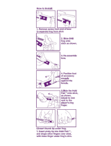
CLAMP VERSION
1. Disengage the stop pin on the mounting bracket, insert
the rack, adjust to one of the three positions and engage the
stop pin.
2. Slide in and engage the stop pin to the rack.
4. Set anti-slip bolt.
5. Assemble the mounting brackets by disengaging the stop
pin, inserting the two brackets together and engaging the
stop pin to secure.
Summary of Steps shown above.
Disengage
Stop Pin
Engage
Stop Pin
1.
2.
3. & 4.
5.
Disengage
Stop Pin
Heel Jaw in
the Fixed
Position
Heel Jaw in
the Mobile
Position
OPERATION

RW30 USER MANUAL - 13
CONNECTING THE WIRE FEED/
WELDING TIP TO THE RW30
1. Place the welding tip into the support.
2. Support swivel blocking lever.
3. Support stick-out lever.
SETTING THE STICK OUT
The ideal setting is 30 mm. Use the template markers to check
for proper distance.
Adjusting the Clamp
Summary of steps shown above.
30 mm
Ideal
Setting
OPERATION

14 - RW30 USER MANUAL
OPERATING THE RW30 & THE
CHARLIE CONTROL UNIT
1. Turn ON the main switch on the RW30.
2. Unlock the ON/OFF switch on the Charlie Control Unit
located on the right side of the unit.
AUTOMATIC TRACK MODE
After preheating, this mode is used on carbon steel track for
continuous surface work on three or four-sided octagonal
polygons.
AUTOMATIC POINTS/FROG MODE
With no preheating, this mode is used on manganese steel
points and frogs. For strip-by-strip work alternately of 1 to 3
three or four-sided polygonal surfaces.
After preheating, this mode is used on carbon steel points
or frogs for continuous surface work on three or four-sided
polygons.
Charlie Control Unit
A computerised control unit to command the welding cycle,
Charlie
®
is presented in a polycarbonate-housing unit equipped
with a liquid crystal display and a six-keypad keyboard under
lexan for man-machine dialog. Its 5 metre shielded mains cord
can be wrapped around its tubular-shaped chassis.
The Charlie
®
control unit is adapted for on-site work. Its protec-
tion rating classies it for uses under all weather conditions.
THE “CHARLIE” CONTROL UNIT CONTROLS
The SCREEN displays messages as well as tracing informa-
tion for the user.
The VALID is used to validate the current step. During a cycle,
it is used to display the welding U and I.
The STOP button is used to return to the previous step. Dur-
ing a cycle, it is used to momentarily or denitively stop the
welding cycle.
The UP and DOWN arrows are used to scroll through the
alphanumeric character list during the tracing data acquisi-
tion stage. In the setting stage, it is used to move the head
along the Y-axis.
The LEFT and RIGHT arrows are used to scroll through the
alphanumeric character list during the tracing data acquisi-
tion stage. In the setting stage, it is used to move the head
along the X-axis.
Rail
Automatic
Mode
Crossing
Automatic
Mode
Display
Screen
Direction
Arrows
Valid Button
Stop/Reset
Button
OPERATION

RW30 USER MANUAL - 15
J.SAURON
TRANSLAMATIC RW30
08 JS 063* du 17/12/2008 02/04/2009
PAGE : 6/68
3.1 Screen examples of scrolling through the alphanumeric character list
_ - - - - - - - - - -
C - - - - - - - - - -
A - - - - - - - - - -
- _ - - - - - - - - -
B - - - - - - - - - -
B - - - - - - - - - -
Examples: movin
g
the cursor from left to ri
g
ht
- - _ - - - - - - - -
Examples: scrollin
g
down the list
Exam
p
les: scrollin
g
u
p
the list
A - - - - - - - - - -
In tracing mode
C - - - - - - - - - -
STOP
VALID
- - _ - - - - - - - -
Examples: movin
g
the cursor from ri
g
ht to left
LINE - - - - - - - - PK - - - -
TRACK DATA
- - - - - - - - - -
Examples: movin
g
forward throu
g
h the operator dialo
g
ue
VALID
PK - - - -
Exam
p
les : movin
g
back throu
g
h the o
p
erator dialo
g
ue
LINE - - - - - - - -
STOP
In welding mode
Example: momentar
y
stop in the weldin
g
c
y
cle
VALID
Example: definitive stop in the weldin
g
c
y
cle
STOP
STOP CYCLE
RESTART CYCLE ?
END LAYER N° X
LAYER N° Y VALID
TRACK DAT A
- - - - - - - - - -
WELDING CYCLE
BEAD XX/XX
RESTART
WELDING CYCLE
STOP
STOP CYCLE
RESTART CYCLE ?
WELDING CYCLE
BEAD XX/XX
STOP
- _ - - - - - - - - - _ - - - - - - - - - -
Below are screen examples of scrolling through the alphanumeric character list.
OPERATION

16 - RW30 USER MANUAL
LANGUAGE SETTING
Different languages may be accessed and selected when
the rst message “HELLO” appears by using the PLUS key.
Translations of the message “HELLO” into different languages
according to geographic areas are then displayed each time
the PLUS key is pressed.
SETTING THE DATE AND TIME
To set the date and time, scroll until “DATE AND TIME” is
displayed. Set the date and time by pressing the PLUS or
MINUS keys. Conrm using the VALID key.
Depending on how the unit is congured, the “DATE TIME”
message may not be displayed if the most succinct level of
operator dialogue is used.
PRINTING DATA
To print the data stored in memory:
1. Make sure that the unit is connected to a power source.
2. Connect either a serial printer (9-pin connector) or a parallel
printer if the unit is equipped with a parallel interface (25-pin
connector).
When using a serial printer, make sure:
1. that the serial printer communication parameters
are set correctly:
• 9600 bauds
• no parity
• 8 data bits
• 1 stop bit
2. that the correct serial cable is used.
3. Make sure the printer is ONLINE and READY.
4. Turn on the unit and scroll to the IMPRESSION step,
available by the automatic detection by the system of the
presence of a printer.
5. Select the output mode:
• Welding number
• Operator ID
• Date
• All
6. Conrm choice using the VALID key.
INFORMATION ON DATA TRACKING
MANUAL DATA ENTRY
Some areas may require manual data entry:
• Operator stamp
• Location, district code, line, mileage point,
track and rail line
• Type of metal deposition
• Type of power source
• Type of rail
• Type of resurfacing.
Two types of manual entries are possible:
1. Character by character mode.
Pressing the PLUS or MINUS keys causes the allowable
characters to be displayed each character is conrmed by
the VALID key.
2. Pre-programmed values.
Pressing the PLUS or MINUS keys causes the various pre-
programmed values to be displayed. Each value is then
conrmed by pressing the VALID key. When the characters
“----” appear, this indicates characters available for manual
character-by-character entry.
AUTOMATIC DATA ENTRY
Data can also be acquired by reading bar codes.
Depending on the software installed in the unit and according
to the user companies’ specications, data may be acquired
automatically. Depending on these specications, data may
be required or optional.
The software includes a standard operator description card
with a 30-digit ISO bar code.
OPERATION

RW30 USER MANUAL - 17
OPERATOR DIALOGUE
Power up:
Then:
Change language - press the arrows:
Display software version and Charlie serial number.
This mode allows to perform free polygons from 3 to 4
sides.
• Setting the points without restriction (beads direction :
Position O1 to Position O2).
• When setting the 4 points, point 4 can be out of the vertical
alignment of point Position O1; without automatic control of
any alignment.
• Welding mode « bead by bead ».
Simple welding mode: Shapes like rectangle, triangle and
butt welding.
• Non stop welding our bead by bead.
• Realization with or without surrounding.
Changing welding modes by pressing:
Memories Test
HELLO
or
CTRL.PROG x.xxx
CHARLIE Nxxxxxxx
NO ALIGNMENT
ALIGNMENT
OK
or
Validate by pressing:
Corrections can be made by pressing:
Note: This is also effective during all welding cycle.
To go to the next step, press:
To step back to the previous step, press:
Welding speed displayed cm/min (1 cm/min equals to 0.4
inch/min) (adjustable value in the parameter menu).
Allow to move the torch according into 2 axis « X » et « Z ».
Set point Position O1. Dene the resurfacing area.
Set point Position O2. The torch cans only moves on the «
X » axis.
ALIGNMENT
OK
SPEED : 30
cm/mn
LAYER 1
TORCH: PO1
PO2
TORCH:
PO3
TORCH:
OPERATION

18 - RW30 USER MANUAL
Set point Position O3. The torch cans only moves on the «
Z » axis.
Set point Position O4. This point should only be set vertically
from point Position O1 with automatic tone of this position.
Display the length and the width of the setting shape (1 mm
equals to 0.04 inch).
Surrounding selection: « YES », or « NO », (continuing bead
from Position O1 to Position O2 then to Position O3 then to
Position O4 and nally to Position O1).
Display the number of beads that will be made during the
resurfacing (the surrounding is not included in this number).
It is possible to modify this number if needed by pressing:
PO4
TORCH:
PO4
TORCH:
PO4
TORCH:
or
or
LENGTH: xxmm
WIDTH: xxmm
SURROUND ?
YES - VALID
SURROUND ?
NO - VALID
NUMBER BEADS:
xx
or
SPACING: x.xx mm
WELD.TIME: xxmin
Display of the step between each bead, (distance in mm, 1 mm
equals to 0.04 inch) and estimate welding time in minutes.
Welding mode choice: bead by bead, « YES », or continue,
« NO ».
If « YES », welding bead by bead (Torch is moving at the be-
ginning of the next bead right after previous bead is done).
If « NO », beads are done in “continue”.
If VALID key is pressed, Torch will move to starting point of
Position O1. Welding will start.
While welding:
Torch moves to starting point of the welding or at the beginning
of the new bead if “bead by bead” mode has been selected.
Surrounding welding if that option has been selected.
Shows the bead’s number in welding, « xxx », and the to-
tal number of beads of the whole resurfacing of the area,
«yyy».
If « bead by bead » option is selected, the following screen
appears at the end of the previous bead and after the torch
is set.
BEADS 1 BY 1 ?
NO - VALID
BEADS 1 BY 1 ?
YES - VALID
WELDING CYCLE
VALID
RETURN TORCH TO
INITIAL POINT
WELDING CYCLE
SURROUND
WELDING CYCLE
BEAD xxx/yyy
VALID TO START
FOLLOWING BEAD
OPERATION

RW30 USER MANUAL - 19
If VALID key is pressed, torch will move to the starting point
of the next bead.
Torch return to starting point and start welding of the next
bead.
When resurfacing is over, the following message proposes
to set a new resurfacing cycle:
If VALID key is pressed, you will have to set a new welding
area. (As previously seen).
If RESET key is pressed:
Allow to place the torch in « Parking » position.
If VALID key is pressed, torch will move to « Parking » posi-
tion.
If RESET key is pressed, back to message:
Note: This is also effective during all welding cycle.
To go to the next step press the VALID key.
To step back to the previous, press the RESET key.
Welding speed displayed cm/min (1 cm/min equals to 0.4
inch/min) (adjustable value in the parameter menu).
RETURN TORCH TO
INITIAL POINT
END LAYER N : 1
LAYER N : 2 - VAL
NEUTRAL POINT ?
TRANSPORT - VALID
HELLO
NO ALIGNMENT
SPEED : 30
cm/mn
Selection of Torch position after the welding of each bead
(evacuation point).
The setting is done as:
Set point position O1.
Set point position O2.
Set point position O3.
Triangle can be weld: if « NO », set point Position O4. If «
YES », needed number of beads will be display.
Set point position O4.
Display the number of beads that will be made during the
resurfacing (the surrounding is not included in this number).
It is possible to modify this number if needed by pressing:
RETRACTING
POINT
PO1
TORCH:
PO2
TORCH:
PO3
TORCH:
TRIANGLE ?
NO - VALID
TRIANGLE ?
YES - VALID
or
PO4
TORCH:
NUMBER BEADS:
xx
or
OPERATION

20 - RW30 USER MANUAL
Display of the step between each bead, (distance in mm, 1 mm
equals to 0.04 inch) and estimate welding time in minutes.
-Setting can be made up to 3 shapes:
Option to repeat the same shape or change the size and
shape as previously indicated.
During welding:
Torch moves to starting point of the rst bead.
Shows the bead’s number in welding, « xxx », and the to-
tal number of beads of the whole resurfacing of the area,
«yyy».
Torch will moves to retracting point after bead.
Press VALID key to start the next bead.
If VALID key is pressed, you will have to set anew welding
area. (As previously seen).
SPACING : x.xx mm
WELD.TIME : xxmin
SETTING SHAPE X ?
NO - VALID
SETTING SHAPE X ?
YES - VALID
RETURN TORCH TO
INITIAL POINT
WELDING CYCLE
BEAD xxx/yyy
MOVE TORCH
VALID TO START
FOLLOWING BEAD
END LAYER N : 1
LAYER N : 2 - VAL
If RESET key is pressed:
Allow to place the torch in « Parking » position.
If VALID key is pressed, torch will move to « Parking » posi-
tion.
If RESET key is pressed, back to message:
STOP AND RESTART OF WELDING CYCLE
During the welding, in whatever mode you have selected,
stopping the welding cycle is always possible:
Pressing the RESET key will stop the weld cycle.
To restart the welding cycle, press VALID key.
According to what mode you are using, a correction of the
exact positioning of the torch during the stopping can be
done:
-Maximum correction: 1 cm following the 2 axis « X » and «
Z »
To stop the welding cycle, press the RESET key.
ERROR MESSAGES
During the setting of the points, some errors message can
appear:
Set Position O2:
The distance between points Position O1 and Position O2
must be minimum or equal to 30mm on « X » axis. (This mes-
sage will be displayed only if the distance between Position
O1 and Position O2 < 30mm). Note : this distance (30mm
equals to 1.18 inch) is set in the parameters menu.
NEUTRAL POINT ?
TRANSPORT - VALID
HELLO
STOP CYCLE
RESTART CYCLE ?
MIN LEN : 30mm !
LENGTH : xx mm
OPERATION
/