Page is loading ...

Page
DZKit
ASSEMBLY MANUAL
PSKube
20 Watt PSK Transceiver
Model PSQ-100
Price: $10.00
DZ CompanY • LOVELAND, COLORADO

Page 2
DZ COMPANY CONTACT INFO
Orders, parts, phone assistance.....................................................................(970) 667-7382
Email orders............................................................................................... [email protected]
Email technical support ......................................................................... [email protected]
Online orders ................................................................. www.dzkit.com/catalog/index.htm
Mail:
DZKit
710 Grove Ct.
Loveland, CO 80537
During your first ninety (90) days of ownership, DZ Company will replace or repair free of charge—as soon as
practical—any parts which are defective, either in materials or workmanship. You can obtain parts directly from
DZ Company by writing us, emailing us or telephoning us. And we’ll pay shipping charges to get those parts to
you—anywhere in the world.
We warrant that during the first ninety (90) days of ownership, our products, when correctly assembled,
calibrated, adjusted and used in accordance with our printed instructions, will meet published specifications.
You will receive free consultation (except for the cost of your long distance phone call) on any problem you may
encounter in the assembly or use of your DZKit product. Just drop us a line, email us, give us a call, or visit our
website and click on “Support”. That will give you access to free on-line support and a discussion group. Sorry,
we cannot accept collect calls.
Our warranty, both expressed and implied, does not cover damage caused by the use of corrosive solder,
defective tools, incorrect assembly, misuse, fire, customer-made modifications, floods or acts of God, nor does it
include reimbursement for customer assembly or setup time. The warranty covers only DZKit products and is
not extended to non-DZ allied equipment or components used in conjunction with our products or uses of our
products for purposes other than as advertised.
If you are ever dissatisfied with our service—warranty or otherwise– or our products, please write or email the
president, Brian Wood, W0DZ, and he will make certain your problems receive prompt, personal attention.
DZ COMPANY
LOVELAND, CO 80537
YOUR DZKIT 90-DAY FULL WARRANTY

Page 3
Assembly
And
Operation
Of the
KIT
20 Watt PSK Transceiver
Model PSQ-100A and PSQ-100B
DZ COMPANY
LOVELAND,
COLORADO
TABLE OF CONTENTS
Introduction...................................... 4
Assembly Notes................................ 5
Step-By-Step Assembly.................... 8
PSQ-100-3,10 Computer, Disk.... 8
PSQ-100-11 RF Amplifier......... 14
PSQ-100-5 DC-DC Converter... 24
PSQ-100-4 Mounting Plate ....... 30
PSQ-100-1 Chassis.................... 32
PSQ-100-2 LCD........................ 44
Chassis Integration .................... 48
Power-up Tests ............................... 52
Final Integration ............................. 54
Operating the PSKube.................... 55
Appendix: Software Installation..... 60
In Case of Difficulty....................... 60
Specifications ................................. 64
Warranty................Inside Front Cover
Copyright © 2003
DZ Co.
All rights reserved
10-12-03 PSQ-100-9

Page 4
The PSKube is a revolution in portable trans-
ceivers. For the first time, it is possible to
connect a keyboard, mouse and antenna to a
transceiver that operates only in digital
modes. It accomplishes this by means of a
tiny but powerful personal computer that runs
a common operating system—Microsoft®
Windows® 98 Second Edition. The computer
in this radio is unlike the microprocessors in
other radios. It is a fully functional IBM-
compatible personal computer with disk in-
terface, on-board SoundBlaster-compatible
audio, networking, COM ports, VGA display,
PS/2 keyboard/mouse, USB, parallel port and
more. Thus, it is possible to use all the bene-
fits of a standard PC, such as easy software
updates over the LAN, connection to the
Internet, running of many different applica-
tion programs, easy customization of the
screen, and a lot more.
The PSKube can be built in several stages
and in several combinations. This manual is
thus a complete assembly and operating man-
ual for the most complicated of the
PSKubes—the PSQ-100B, which has an in-
ternal flat panel display, mounting plate for a
PSK transceiver made by Small Wonder
Labs, and an optional 20 Watt amplifier. Fi-
nally, the chassis can be used as a simple
holder for other projects.
INTRODUCTION
Microsoft and Windows are U.S. registered trademarks of Microsoft Corporation.

Page 5
This manual is organized in parts that relate
to the various products that can be ordered
separately to build a PSKube. Although
each part can stand on its own, if you are
building a complete PSKube, we recom-
mend that you start at the beginning and
work your way through the manual in order.
Each circuit part has its own component
number (R1, L4, Q3, etc.). R1 on one as-
sembly will not be the same as R1 on a dif-
ferent assembly, so be sure you are looking
at the right set of parts when comparing part
numbers with the printed parts list. Check
off each part at the beginning of each sec-
tion to make sure all the parts are there. If
you find any missing, give us a call or email
us and we will rush a replacement to you.
Most electronic kits that are returned for
service have poor soldering jobs. Please
take a moment to familiarize yourself with
proper soldering technique. And do not, un-
der ANY circumstances, use corrosive
(“acid-core”) solder! That will void your
warranty and render your kit inoperative.
Resistors are identified by their values in
Ohms, Kilohms (k) or Megohms (M) and
by the color code:
The first two bands represent the numeric
value and the third band represents the mul-
Resistor Color Code Chart
tiplier, which is a power of 10. Thus, a 56
Ohm resistor is Green-Blue-Black. A
10KOhm resistor is Brown-Black-Orange,
and so on. The fourth band is the toler-
ance—no band represents 20%, a silver
band is 10%, and a gold band is 5%. One
percent resistors use 4 bands for the value
using the same color scheme.
Capacitors are identified by their type—
disk, polystyrene, polypropylene, electro-
lytic, trimmer, etc.) and capacitance values
are in microfarads (uF) or picoFarads (pF).
Inductors are represented either by their in-
ductance in microHenries (uH) or by the
number of turns in the coil if you are doing
the winding.
When a solder connection is to be made, it
is designated (S-n), where n is the number
of wires or parts to be soldered. For exam-
ple, (S-1) means to solder one wire to the
noted part. If a connection is to be soldered
later, because other parts will later be
added, it is shown as NO SOLDER (NS).
ASSEMBLY NOTES
Black 0 Yellow 4 Gray 8
Brown 1 Green 5 White 9
Red 2 Blue 6 Silver /10
Orange 3 Violet 7 Gold /100
Most kit builders find it helpful to sepa-
rate the parts into categories for quick
identification. Muffin tins and egg car-
tons serve this purpose admirably.

Page 6
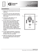
SOLDERING INSTRUCTIONS
Poor soldering accounts for almost 90% of all kit building problems. The photographs below
show examples of the most common types of bad solder connections and a good one. If you lo-
cate any of these bad solder connections in your kit, correct them as described. Study this sec-
tion carefully before you start building your kit.
Use a good quality, low wattage (25-100W)
soldering iron and non-corrosive, rosin core
solder to assemble your kit. Keep the sponge
damp and wipe the tip on the sponge after
each solder step.
Solder blob. In this example, solder flowed
onto a lead, but the heat was not maintained
long enough for it to flow onto the circuit
board pad. Solution: reheat the connection,
touching the iron to both the component lead
and the pad at the same time.
Solder bridge. Solder that stretches from
one trace to another creates a short circuit.
Solution: Hold the board upside down and
reheat the area. The excess solder will flow
down the soldering iron. Another solution is
to use a “solder sucker” or solder wick to
remove excess solder. Solder suckers work
well one or two times on a given connection.
If used too much, they can pull pads and
traces off of PC boards.
Good solder connections. A good solder
connection looks like this. Solder flows
evenly onto both the part and the PC board
or chassis component. It is shiny and even,
not lumpy and dull. Component leads that
are properly soldered can not be moved in
the hole.

Page 7
STATIC PRECAUTIONS
Many of the components in your kit can be
damaged by exposure to static electricity.
Please read this page to familiarize yourself
with the causes of and solutions to this prob-
lem.
When the climate is dry, you can generate
thousands of volts simply by walking across
a carpet. When you then touch a metal object
you can feel the effects of this as you draw a
spark! That same spark, often too small to see
or feel, can destroy sensitive electronic com-
ponents. You MUST take precautions when
working with electronics to prevent damage.
The best solution is to outfit your workbench
with anti-static devices — floormats,
grounded soldering irons, and workmats with
grounded wriststraps. If these are not practi-
cal for you, the very least you should do is to
discharge yourself to ground after you sit
down and before you touch any electronic
items, by touching a grounded object such as
the corner of a wall.
In a dry environment, simply standing up af-
ter sitting in a non-grounded chair can also
charge you with electricity. If you stand up to
stretch, for example, be sure to re-ground
yourself before getting back to work.
All electronic components are susceptible to
static, but semiconductors and assembled
boards containing semiconductors are the
most prone to damage. These include diodes
(including light-emitting diodes [LEDs]),
transistors and integrated circuits (ICs).
You are a walking lightning bolt! Be
careful!

Page 8
Computer - PSQ-100-3
PIC (√) QTY DESCRIPTION
A1 ( ) 1 Single Board Computer, cables,
software drivers
A1 ( ) 1 128MB SODIMM memory
A1 ( ) 1 PS/2 fold-up keyboard
A1 ( ) 1 PS/2 mouse
A1 ( ) 1 Dual pouch fabric bag for kbd, mouse
A2 ( ) 1 Metal mounting plate
Hardware Pack (Marked PSQ-100-3 HW Pack”)
B1 ( ) 4 #6 x 5/16" spacer
B2 ( ) 4 6-32 x 5/8" panhead machine screw
B3 ( ) 4 6-32 x 5/16" panhead machine screw
B4 ( ) 8 6-32 keps nut
Other
C1 ( ) 1 Bracket bag: Includes 2 support angle
brackets, 4 6-32 clip nuts, 4 6-32 x 5/16”
panhead machine screws and assembly
instructions
C2 ( )
1 DB-9 female to female adapter ("gender
changer")
PARTS LIST
COMPUTER (PSQ-100-3)
And
DISK DRIVE (PSQ-100-10)
IMPORTANT NOTE: The computer and disk drive must be assembled as one unit. If you have
not purchased the PSQ-100-10, make sure that you have an equivalent set of parts available.
This is necessary because the disk drive fastens to the underside of the computer mounting
plate, and thus the disk mounting screws are underneath the computer.
A1
A2
B1 B2 B3 B4
C1
C2

Page 9
Disk Drive - PSQ-100-10
PIC (√) QTY DESCRIPTION
A1 ( ) 1 2.5” Laptop Hard Drive
A2 ( ) 1 Windows 98SE OEM license
Hardware Pack
B1 ( ) 4 M3 x 5mm machine screw
B2 ( ) 4 M3 Flat washer
B1 B2
A1 A2

Page 10
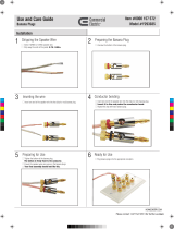
STEP-BY-STEP ASSEMBLY
Refer to Pictorial 1.
() Locate the Bracket bag. Attach the captive
nuts to the sides as shown in the documenta-
tion that comes with the angle bracket kit.
() Attach the angle brackets to the mounting
plate with 4 6-32 x 5/16” screws and 4 keps
nuts.
() Position the assembly as shown, with the
brackets extending out past the end of the
plate, facing you. On the left side, cut the
bracket as shown using wire cutters. The
metal is very soft and will cut easily. This
notch provides clearance for the display.
() Remove the PC card from its antistatic
package. It is best if you have an antistatic
work area (grounded wrist strap, floor mat,
etc.). If not, be absolutely sure that you have
discharged any static buildup in your body by
touching a grounded metal object prior to
working with this sensitive board.
Note: The next step installs memory cards.
These modules can only fit into the sockets
one way.
() Install the SODIMM card so that its gold
pins point down into the SODIMM socket.
Slip the SODIMM into the socket at a 45 de-
gree angle and carefully fit the bottom of the
card against the connectors. Gently push the
SODIMM into a perpendicular position until
the clips on the ends of the SODIMM sockets
snap into place. Check to ensure that the
SODIMM is correctly seated and all
connector contacts touch. The SODIMM
should not move around in its socket.
() If you want to use a Compact Flash (Type
I) memory card as a secondary “disk” (not
provided), insert it into the holder at this
time. Note: while it is possible to boot an op-
erating system from this solid state memory,
it is not recommended. Tests have indicated
that the lifetime of such a memory is very
limited. This is because flash memories are
constrained by the type of construction to
have a limited number of read/write cycles,
and this lifetime is quickly reached with a
Microsoft Windows operating system due to
the constant reading and writing of large data
files. However, it will work fine as a backup
drive.
Detail 1

Page 11
Pictorial 1

Page 12
() Attach a 2.5” Hard Drive (such as the
PSQ-100-10) to the bottom side of the
mounting plate with the connector facing the
side where the angle brackets extend out
from the plate. Use 4 M3 flat-head screws
and washers. It is easiest to do this by placing
the disk on a flat surface, placing the washers
into position on the 4 mounting holes, and
then carefully laying the plate on top. Con-
nect the IDE cable to the disk drive, being
careful to align pin one as shown.
() Attach the Single Board Computer to the
top of the mounting plate using four 5/16”
spacers, 6-32 x 5/8” screws and KEPS nuts.
Orient the board so that the connectors face
the side of the plate where the angle brackets
are flush with the plate.
() Attach the IDE cable (flat ribbon cable)
from the disk drive to the PC, being careful to
observe the location of pin 1 (striped side of
cable, pin 1 marked on board with white tri-
angle). Fold the cable as shown. Note! If you
are installing software yourself, you can con-
nect a floppy drive to the floppy drive con-
nector (cable included), and you can replace
the IDE cable with one that has both a 44-pin
CD ROM connector AND a 2.5” hard drive
connector, such as the PSQ-100-8.
() Attach the RS-232C cable to the connector
labeled COM2. This cable divides into two
pieces. Cut off the section with only 4 wires.
Wrap electrical tape around the loose end and
make sure the individual wires do not touch
each other.
() Attach the audio cable to the audio con-
nector.
() Pull the audio jumper off its 3-pin connec-
tor and move it to the other side of the con-
nector as shown in Detail 2. This allows 12V
to go to the on-board amplifier and provides
better sound quality. DO NOT change this
jumper when power is on!
Detail 2. Audio Jumper
This completes assembly of the internal PC
and disk drive.

Page 13
Photo 1. Top of plate
Photo 2. Bottom of plate

Page 14
RF AMPLIFIER (PSQ-100-11)
PARTS LIST
PIC (√) QTY DESCRIPTION
Capacitors:
A1 ( ) 1 220 uF/25V electrolytic (C1)
A1 ( ) 2 10 uF/25V electrolytic (C2, C13)
A2 ( ) 7 0.1 uF disk ceramic
(C3, C8, C9, C10, C11, C14, C15)
A2 ( ) 1 47 pF disk ceramic (C16)
A2 ( ) 2 180 pF disk ceramic (C4, C7)
A2 ( ) 2 330 pF disk ceramic (C5, C6)
A2 ( ) 1 0.01 uF disk ceramic (C12)
Resistors (1/4 Watt, 5% except where noted):
B1 ( ) 2 27 ohm 1/2W (red-violet-black) (R6,R7)
B1 ( ) 1 330 ohm (orange-orange-brown) (R5)
B1 ( ) 1 470 ohm (yellow-violet-brown) (R1)
B1 ( ) 1 2.2K ohm (red-red-red) (R3)
B1 ( ) 1 10K ohm (brown-black-orange) (R4)
B1 ( ) 1 100K ohm (brown-black-yellow) (R2)
B2 ( ) 2 5K ohm 1/2W potentiometer (RV1, RV2)
Semiconductors:
C1 ( ) 1 1N5231B 5.1V 1/2W Zener diode (CR1)
C1 ( ) 2 1N4148 signal diode (CR2, CR3)
C1 ( ) 1 1N4002 diode (CR4)
C2 ( ) 2 IRF-510 Power MOSFET (Q1, Q2)
C3 ( ) 2 2N3904 NPN transistor (Q3, Q4)
C3 ( ) 1 2N3906 PNP transistor (Q5)
A1
A2
B1
C3
B2
C1
C2
1/4 Watt
1/2 Watt

Page 15
Other:
D1 ( ) 1 DPDT relay, 12V (K1)
D2 ( ) 1 PC-mount pushbutton switch (S1)
D3 ( ) 2 BNC PC-mount jack (J1, J2)
D4 ( ) 2 Heat sink
D5 ( ) 3 Yellow toroid core (L1, L2, L3)
D6 ( ) 1 2 hole small ferrite transformer core (T1)
D7 ( ) 1 2 hole large ferrite transformer core (T2)
D8 ( ) 2 4-40 x 5/16” panhead machine screw
D9 ( ) 2 4-40 keps nut
D10 ( ) 1 Tube of thermal heatsink compound
D11 ( ) 2 12V miniature fan
D12 ( ) 1 RF amplifier PC board
( ) 7’ #24 enameled magnet wire
( ) 2” Double-stick tape
D12
D6
D1
D3
D2
D11
D8
D5
D10
D7 D4
D9

Page 16
L1 and L3 (Toroids)
() Cut 8” of magnet wire (thin, enameled
wire) and thread it through the donut-shaped
toroid cores exactly 12 times as shown. Pull
each turn gently to make the wire snug but
not overly tight. Tin the ends by holding the
soldering iron on the ends of the leads while
applying a small bit of solder to melt away
the insulation. It doesn’t matter which side of
the core you start from and you can ignore
the color difference, if any, from one side to
the other.
Detail 1. L1, L3 toroid construction
L2 (Toroid)
() Cut 9.5” of magnet wire. Thread it
through the toroid exactly 13 times, using the
same procedure as in the previous step. Sepa-
rate this from the other two finished toroids
so that you don’t get them mistaken for each
other.
T1 (Small ferrite core with two holes)
() Cut 11” of magnet wire and thread it
through the smaller ferrite core 6 times. Pull
gently to make each turn snug but not overly
tight. Tin the ends as described above. This is
the primary side of the transformer. Mark it
with a magic marker or pencil so that you can
identify this side when you install it.
() Cut 9” of magnet wire and thread 5 turns
through the same holes so that the leads exit
the other side. Tin the ends. This is the secon-
dary side.
STEP-BY-STEP ASSEMBLY
Detail 3. Transformer T1 construction
Detail 2. L2 toroid construction

Page 17
T2 (Large ferrite core with two holes)
() Cut 9.5” of magnet wire. Wind one turn,
then bring the end out one inch and make a
loop. Twist the two sides of the loop together
to form a center-tap, then thread the rest of
the wire through the core 1 more time. Pull
gently to make each turn snug but not overly
tight. Tin the ends as described above. This is
the center-tapped primary side of the trans-
former.
() Cut 10” of magnet wire and thread 3 turns
through the same holes so that the leads
exit the other side. Tin the ends. Mark the
leads with tape or other identification. This
is the secondary side.
L4, L5 (Air-wound coils)
() Cut two 10” lengths of magnet wire. Wrap
each piece tightly around a pencil or other
1/4” diameter cylindrical object 9 times, then
slide the coil off the pencil and gently push
the coil together to form a cylinder about 1/2”
long. Bend the leads at right angles to the
body of the coils. Tin the ends as described
above.
Cut at the X and heat
each lead to remove
enamel insulation, then
twist together.
Detail 4. Transformer T2 construction
Detail 5. Coils L4, L5 construction

Page 18
Solder all parts as they are installed
and then cut leads as close as practical
to the solder.
() Q1, Q2: Bend MOSFET leads
such that they and the mounting
hole line up. Dab heatsink grease
on underside of MOSFET. Insert a
4-40 x 5/16” mounting screw from
the top through the transistor and
then the heatsink. Insert the MOS-
FET and heatsink into the board
and secure the screw with a 4-40
keps nut. Tighten the nut.
( ) C15: 47 pF disk ceramic
( ) C4: 180 pF disk ceramic
( ) L1: 12-turn toroid
( ) C5: 330 pF disk ceramic
( ) L2: 13-turn toroid
( ) C6: 330 pF disk ceramic
( ) L3: 12-turn toroid
( ) C7: 180 pF disk ceramic
( ) CR1: 5.1V Zener diode
( ) J1: BNC connector
( ) K1: Relay
( ) CR4: 1N4002 diode
( ) J2: BNC connector

Page 19
( ) S1: Switch
( ) C1: 220 uF electrolytic
See polarity detail above.
( ) C3: 0.1 uF disk ceramic
( ) C13: 10 uF electrolytic
See polarity detail above.
( ) C14: 0.1 uF disk ceramic
( ) C8, C9, C10, C11: 0.1 uF
disk ceramic
( ) C12: 0.01 uF disk ce-
ramic
( ) RV1, RV2: Potentiome-
ters
( ) C2: 10 uF electrolytic.
See polarity detail above.
Detail 6. Electrolytic
capacitor polarity

Page 20
( ) L4, L5: 9-turn air-wound
coil
( ) Q3, Q4: 2N3904 NPN
transistor
( ) CR2, CR3: 1N4148 diode
(match polarity band)
( ) Q5: 2N3906 PNP transis-
tor
( ) R1: 470 Ohm (yellow-
violet-brown)
( ) R2: 100K (brown-black-
yellow)
( ) R3: 2.2K (red-red-red)
( ) R4: 10K (brown-black-
orange)
( ) R5: 330 Ohm (orange-
orange-brown)
() T2: Large trans-
former
() R6, R7: 27 Ohm
1/2W (red-violet-
black)
() T1: Small trans-
former. The primary
side (previously
marked) goes on the
side closest to connec-
tors J1, J2.
Keep your soldering tip clean by wiping it
off against a wet sponge periodically.
/