Rockford Fosgate RFX-8102 Installation guide
- Category
- Motorcycle Accessories
- Type
- Installation guide

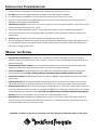
1. Carefully read and understand the instructions before attempting to install the Source Unit.
2. For safety, disconnect the negative lead from the battery prior to beginning the installation.
3. For easier assembly, we suggest you run all wires prior to mounting your Source Unit in place.
4. Route all of the RCA cables close together and away from any high current wires to prevent coupling noise from
radiated electrical fields into the audio signal.
5. Think before your drill! Be careful not to cut or drill into gas tanks, fuel lines, brake or hydraulic lines, vacuum lines or
electrical wiring when working on any vehicle.
6. Never run the cable underneath the vehicle. Running the cable inside the vehicle provides the best protection.
7. Avoid running the cable over or through sharp edges. Use rubber or plastic grommets to protect any cable routed
through metal.
8. ALWAYS protect the battery and electrical system from damage with proper fusing.
9. When grounding to the chassis of the vehicle, scrape all paint from the metal to ensure a good, clean ground connec-
tion. Grounding connections should be as short as possible and always be connected to metal that is welded to the
main body, or chassis, of the vehicle.
INSTALLATION CONSIDERATIONS
®®
ATTENTION: To maintain your warranty, we recommend your Authorized Rockford Fosgate Dealer install your Source Unit.
1. Determine the mounting angle of the source unit. The source unit should be mounted as close to horizontal as
possible to maximize the performance of the CD Player. The source unit can accommodate mounting angles of up to
±20° from horizontal.
2. Install the Speaker/Power Harness by connecting the corresponding wires to the electrical and audio system (see
diagram on reverse page). Solder and heat shrink all connections for a reliable installation.
3. Connect the Speakers (if external amplifiers are not used) to the corresponding output wires. Be sure to maintain
proper speaker polarity.
DO NOT chassis ground any of the speaker leads as unstable operation may result.
4. Install the RCA Harness (if external amplifiers will be used) by plugging the signal cables into the source unit's RCA
output jack(s).
5. Perform a final check of the completed system wiring to ensure that all connections are accurate. Check all power
and ground connections for frayed wires and loose connections which could cause problems from road vibrations.
6. Install the Source Unit securely to the vehicle using the “Standard Mount” or “ISO Mount” method (refer to page 23 of
the Owner's Manual for further information). If using the “Standard Mount” method, be sure the source unit is installed
using the backstrap and installation sleeve. CAUTION: The Installation sleeve should be installed using the appropri-
ate tabs (see chart on reverse page). Use only screws with a maximum length of 8 mm.
7. Wire the Source Unit by plugging in the Speaker/Power Harness, RCA Harness (if used), CDX cable (if used), and
Antenna to the connectors located at the rear of the source unit. For “Standard Mounting,” slide the source unit into
the Mounting Sleeve until it clicks firmly into place.
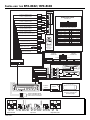
WIRING THE SYSTEM

INSTALLING THE RFX-8102 / RFX-8103
1
2
3
4
5
6
7
8
9
10
11
12
13
14
15
16
17
18
19
20
21
22
N/C
Turn-On “B”
Turn-On “A”
Turn-On “C“
Audio Mute
N/C
Rear (L–)
Rear (R–)
Front (L–)
Front (R–)
Chassis Ground
(Blue/White)
(Blue)
(Blue/Red)
(Brown)
(Green/Black)
(Purple/Black)
(White/Black)
(Gray/Black)
(Black)
N/C
N/C
Dimmer
Ignition +12V
N/C
N/C
Rear (L+)
Rear (R+)
Front (L+)
Front (R+)
Battery +12V
(Orange)
(Red)
(Green)
(Purple)
(White)
(Gray)
(Yellow)
Speaker/Power Harness
Part #FA-1279
(Looking into the Radio Connector)
22 21 20 19 18 17 16 15 14 13 12
1110987654321
1-6
+
–
®
White
White/Black
Gray
Gray/Black
Green
Green/Black
Purple
Purple/Black
Orange
Brown
Blue/Red
Blue/White
Yellow
Red
Blue
Black
Front (L+) (Speaker Output)
Front (L–) (Speaker Output)
Front (R+) (Speaker Output)
Front (R–) (Speaker Output)
Rear (L+) (Speaker Output)
Rear (L–) (Speaker Output)
Rear (R+) (Speaker Output)
Rear (R–) (Speaker Output)
Dimmer (+12V to activate) (Input)
Audio Mute (GND to activate) (Input)
4 Speaker System
2 Speaker System
IR Remote
RFX-1110
Press “Diamond R”
Button to Pulse
Turn on “C”
Turn-On “C” (300mA Max) (Output)
(Pulsed 500ms)
Turn-On “B” (300mA Max) (Output)
(.5 sec DELAY ON – FAST OFF)
Turn-On “A” (2.0 Amp Max) (Output)
(FAST ON – .5 sec DELAY OFF)
Battery +12V (Input)
10A Fuse
Ignition (switched +12V) (Input)
Chassis Ground (Input)
Battery Replacment
(2) CR2032
RFX-8103
Part #FA-1278
RFX-8102
Part #FA-1283
RCA Harness
10
9
8
7
6
5
4
3
2
1
RFX-8103 Only
Subwoofer (–)
Subwoofer (+)
3
4
5
6
7
8
9
10
1
2
(Looking into the Radio Connector)
Front Right (–)
Front Right (+)
Front Left (–)
Front Left (+)
Rear Right (–)
Rear Right (+)
Rear Left (–)
Rear Left (+)
G
R
E
E
N
G
R
A
Y
R
E
D
Front Output White (Left)
*Sub Output on RFX-8103 only
Sub Output* Red (Mono)
Sub Output* White (Mono)
Rear Output Red (Right)
Rear Output White (Left)
Front Output Red (Right)
+ L– + R– – R+– L+
Antenna
Input
Minimum & Maximum
Mounting Angle
Antenna
Refer to INSTALLATION
section of the Manual for a
callout on the 13-Pin DIN.
20°
20°
+
–
+
–
+
–
+
–
Gain
R
Unbal.
Pass
Thru
Bal.
Input
L
0°-180
°
EZ-180°-0
°
Bridged
Gain
Bal.
Speaker
+ L –
Speaker
– R +
RL (Mono)
RFX-8103
®®
AUD
SEL
6
RDMRPTSCAN PAUSED.SCN DIM
43 521
P.SCN LOUDDSPL
CLOCK ILLUM
PWR
AUTO
VOL
TUNE
COMPACT
DIGITAL AUDIO
G
Right Side View
Left Side View
Top View
C
C
B
F A D E
E
A
D
F
B
C
G
C
MAN-1285-A
-
 1
1
-
 2
2


Rockford Fosgate RFX-8102 Installation guide
- Category
- Motorcycle Accessories
- Type
- Installation guide
Ask a question and I''ll find the answer in the document
Finding information in a document is now easier with AI
Related papers
-
 Rockford Fosgate RFX8230 User manual
-
 Rockford Fosgate RFX9220M User manual
-
 Rockford Fosgate RFX3000 Operating instructions
-
 Rockford Fosgate RFX-8030 Operation & Installation
-
 Rockford Fosgate RFX9320R Installation & Operation Manual
-
Philips RFX9200R Specification
-
 Rockford Fosgate RFX3000 Owner's manual
-
 Rockford Fosgate RFX6000-SX Operating instructions
-
 Rockford Fosgate RFX9020M User manual
-
 Rockford Fosgate RFX4000-SX Operating instructions


Other documents
-
CableWholesale 8103-88125 Datasheet
-
 Universal MSC-400 Reference guide
-
E-Mu 1820 Owner's manual
-
 E-Mu 1616m Owner's manual
-
E-Mu 1212M Owner's manual
-
Zoom RFX-1100 User manual
-
-
Rosewill RCW-H9011 Datasheet
-
Rosewill RCDM-10005 Datasheet
-
Universal Remote Control MRF-300/RFX150 User manual

