SAFETY INSTRUCTIONS
A
This safety symbol means
WARNING or CAUTION-
Read the instruction because
it
has to
do with safety. Failure to comply with
the instruction may result in personal
injury.
PERSONALSAFETY INSTRUCTION
This manual is intended to be a service and
repair manual only. The safety instructions
provided in this manual are for the trouble-
shooting and service of the product only.
Individual owners manuals will contain safety
information for the operation of products that
are fitted with the engine described in this
manual.
Operators manuals with complete operational
safety instructions are available through:
The Toro Company
Publications Department
81 11 Lyndale Avenue South
Minneapolis, MN 55420 U.S.A.
Be sure to include the model and serial number
of your machine.
If
you have any questions concerning this
Repair Manual, please contact:
The Tor0 Company
Service Department
81 11 Lyndale Avenue South
Minneapolis,
MN
55420 U.S.A.
ments, keep clear of the PTO shaft, cutting
blades and other moving parts.
7.
Do
not overspeed the engine by changing
the governor settings. Maximum engine
speed with no load is listed in the engine
specifications on page
2.
8. The engine must be stopped before check-
ing the oil or adding oil to the crankcase.
9.
Do
not touch the engine muffler or guard
while the engine is running or soon after it
has stopped. These areas could be hot
enough to cause a burn.
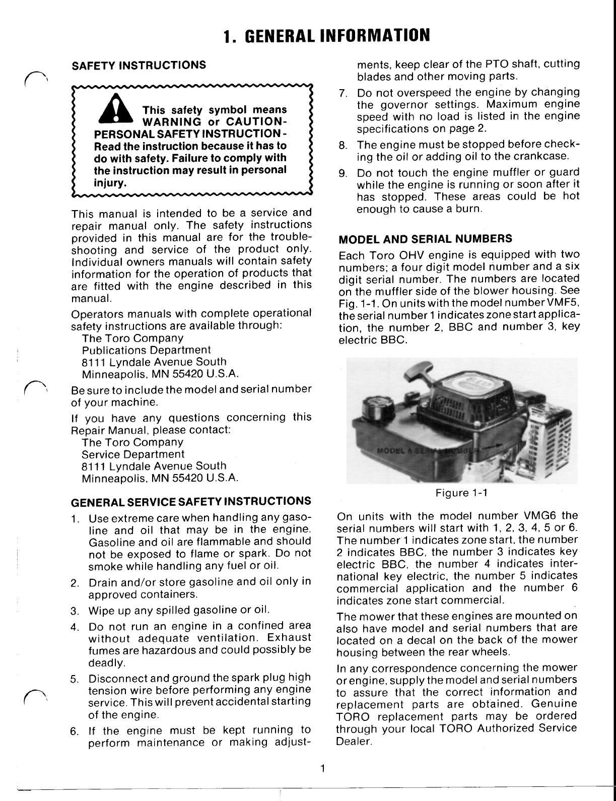
MODEL AND SERIAL NUMBERS
Each Toro OHV engine is equipped with two
numbers: a four digit model number and a six
digit serial number. The numbers are located
on the muffler side of the blower housing. See
Fig. 1-1. On units with the model number VMF5,
the serial number 1 indicates zone start applica-
tion, the number
2,
BBC and number
3,
key
electric BBC.
GENERAL SERVICE SAFETY INSTRUCTIONS
1.
Use extreme care when handling any gaso-
line and oil that may be in the engine.
Gasoline and oil are flammable and should
not be exposed to flame or spark. Do not
smoke while handling any fuel or oil.
2. Drain and/or store gasoline and oil only in
approved containers.
3.
Wipe up any spilled gasoline or oil.
4. Do not run an engine in a confined area
without adequate ventilation. Exhaust
fumes are hazardous and could possibly be
deadly.
5.
Disconnect and ground the spark plug high
tension wire before performing any engine
service. This will prevent accidental starting
of the engine.
6.
If the engine must be kept running to
perform maintenance
or
making adjust-
Figure 1-1
On units with the model number VMG6 the
serial numbers will start with 1,
2,
3,
4,
5
or 6.
The number.1 indicates zone start, the number
2 indicates BBC, the number
3
indicates key
electric BBC, the number 4 indicates inter-
national key electric, the number
5
indicates
commercial application and the number
6
indicates zone start commercial.
The mower that these engines are mounted on
also have model and serial numbers that are
located on a decal on the back of the mower
housing between the rear wheels.
In any correspondence concerning the mower
or engine, supply the model and serial numbers
to assure that the correct information and
replacement parts are obtained. Genuine
TORO replacement parts may be ordered
through your local TORO Authorized Service
Dealer.
1


