Page is loading ...

American DJ Supply
4295 Charter Street
Los Angeles Ca. 90058
(323) 582-2650
(323) 582-2610
www.americandj.com
American DJ®
User Instructions
Rampage
Introduction:
Thank you for purchasing the Rampage™ DMX controller from
American DJ®. To optimize the performance of this product,
please read these operating instructions carefully to familiarize
yourself with the basic operations of this unit. The American DJ®
Rampage™ is a unique intelligent moon ower. This unit can be
controlled by a standard DMX controller or can be linked together
with several unit to form a synchronized light show. The Rampage
comes with 16 gobos plus a spot, several of the gobos have multi-
color combinations. This unit has been tested at the factory before
being shipped to you, there is no assembly required.
Customer Support:
American DJ provides a toll free customer support line, to provide
set up help and to answer any question should you encounter
problems during your set up or initial operation. You may also visit
us on the web at www.americandj.com for any comments or sug-
gestions.
Service Hours are Monday through Friday 10:00 a.m. to 5:00 p.m.
Pacic Time.
Voice: (800) 322-6337
Fax: (323) 582-2610
Warning!
To prevent or reduce the risk of electrical shock or re, do not
expose this unit to rain or moisture. Clearing memory often may
cause damage to the memory chip, be careful not to re initialize
your unit frequency often to avoid this risk. Only use the recom-
mended AC/DC power adaptor.
Caution!
There are no user serviceable parts inside this unit. Do not
attempt any repairs yourself, doing so will void your manufac-
tures warranty. In the unlikely event your unit may require service,
please contact your nearest American DJ dealer.
©American DJ Supply® www.americandj.com Rampage Instruction Manual Page 2

Set Up:
Power Supply: Before plugging your unit in be sure the source volt-
age in your area matches the required voltage for your American DJ®
Rampage.™ The Rampage™ is available in a 115v and 230v version.
Because line voltage may vary from venue to venue, you should be sure
to plug your power supply into a matching wall outlet before attempting
to operate you controller.
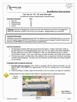
Data Cable (DMX Cable) Requirements:
Your xture and your controller require a
standard 3-pin XLR connector for data
input and data output (Figure 1). If you
are making your own cables be sure
to use standard two conductor shielded
cable (This cable may be purchased at
almost all pro sound and lighting stores).
Your cables should be made with a male
and female XLR connector on either end
of the cable. Also, remember that DMX
cable must be daisy chained and can
not be “Y”ed or split.
Notice: Do not use the ground lug on the XLR connector. Do
not connect the cable’s shield conductor to the ground lug or allow
the shield conductor to come in contact with the XLR’s outer casing.
Grounding the shield could cause a short circuit and erratic behavior.
Figure 1
Figure 2
1
2
3
1
2
3
DMX +
DMX -
COMMON
DMX512 IN
(X-CALIBUR)
CONNECTOR
3 PIN
DMX512 OUT
CONTROLLER
CONNECTOR
3 PIN
1
2
3
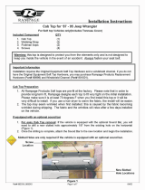
Termination reduces signal errors and
avoids signal transmission problems
and interference. It is always advisable
to connect a DMX terminal, (Resistance
120 Ohm 1/4 W) between PIN 2 (DMX-)
and PIN 3 (DMX +) of the last fixture.
SOUND
REMOTE
CONTROL
INPUT
POWER
INPUT OUTPUT
SOUND
REMOTE
CONTROL
INPUT
POWER
INPUT OUTPUT
SOUND
REMOTE
CONTROL
INPUT
POWER
INPUT OUTPUT
DMX512
DMX+,DMX-,COMMON
©American DJ Supply® www.americandj.com Rampage Instruction Manual Page 3
XLR MALE SOCKET
1 EARTH
2 COLD
2 HOT
XLR FEMALE SOCKET
1 EARTH
COLD 2
3 HOT
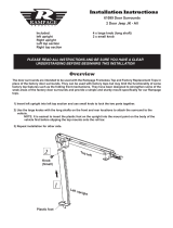
XLR Pin Configuration:
Pin 1 = Shield
Pin 2 = Data Compliment (negative)
Pin 3 = Data True (positive)
Figure 3
Special Note: Line Termination.
When longer runs of cable
are used, you may need to use a terminator on the last unit to avoid
erratic behavior. A terminator is a 90 - 120 ohm 1/4 watt resistor which is
connected between pins 2 and 3 of a male XLR connector (DATA + and
DATA -). This unit is inserted in the female XLR connector of the last
1
2
3
1
2
3
DMX +
DMX -
COMMON
DMX512 IN
(X-CALIBUR)
CONNECTOR
3 PIN
DMX512 OUT
CONTROLLER
CONNECTOR
3 PIN
1
2
3
Termination reduces signal errors and
avoids signal transmission problems
and interference. It is always advisable
to connect a DMX terminal, (Resistance
120 Ohm 1/4 W) between PIN 2 (DMX-)
and PIN 3 (DMX +) of the last fixture.
SOUND
REMOTE
CONTROL
INPUT
POWER
INPUT OUT PUT
SOUND
REMOTE
CONTROL
INPUT
POWER
INPUT OUT PUT
SOUND
REMOTE
CONTROL
INPUT
POWER
INPUT OUT PUT
DMX512
DMX+,DMX-,COMMON
1
2
3
1
2
3
DMX +
DMX -
COMMON
DMX512 IN
(X-CALIBUR)
CONNECTOR
3 PIN
DMX512 OUT
CONTROLLER
CONNECTOR
3 PIN
1
2
3
Termination reduces signal errors and
avoids signal transmission problems
and interference. It is always advisable
to connect a DMX terminal, (Resistance
120 Ohm 1/4 W) between PIN 2 (DMX-)
and PIN 3 (DMX +) of the last fixture.
SOUND
REMOTE
CONTROL
INPUT
POWER
INPUT OUTPUT
SOUND
REMOTE
CONTROL
INPUT
POWER
INPUT OUTPUT
SOUND
REMOTE
CONTROL
INPUT
POWER
INPUT OUTPUT
DMX512
DMX+,DMX-,COMMON
©American DJ Supply® www.americandj.com Rampage Instruction Manual Page 4
Linking:
Your Rampage comes with several built in programs. These programs
will automatically run to the beat of music. For a more dramatic effect
link several Rampage units together. Each Rampage can act a “Master
Unit” that can control up to 15 more units. Link the units together using
standard DMX cable. Follow the Master/Slave Dip Switch Chart on page
7 for proper dip switch settings. The built programs are optimized for a
four unit chase.

The 1/4” phone plug on the unit is for the optional Rampage/C. Do
not attempt to connect an audio signal this jack, this will damage
the PC board and void your manufactures warranty!
Lamp Replacement: Caution! Never open the unit when in use.
Always disconnect the main power before attempting to replace the
lamp. Remember always replace with the same type lamp and fuse.
1. Be sure to follow the proper procedures when handling halogen
bulbs.
2. Loosen the screw on trap door located on top of the unit.
3. Remove the trap door.
4. Remove and replace the bulb.
5. Reassemble.
Fixture Cleaning:
Due to fog residue, smoke, and dust cleaning the internal and external
optical lenses must be carried out periodically to optimize light output.
1. Use normal glass cleaner and a soft cloth to wipe down the
outside casing.
2. Use a brush to wipe down the fan grill and remove as much
built up as possible.
3. Clean the external optics with glass cleaner and a soft cloth
every 20 days.
4. Clean the internal optics with glass cleaner and a soft cloth
every 30-60 days.
5. Always be sure to dry all parts completely before plugging the
unit in.
Cleaning frequency depends on the environment in which the fixture
operates (i.e. smoke, fog residue, dust, dew).
The American DJ Rampage™ comes with a one (1) year limited war-
ranty. We recommend filling out the warranty registration card that
came with your fixture to validate your warranty. For service contact
©American DJ Supply® www.americandj.com Rampage Instruction Manual Page 6
OPERATING INSTRUCTIONS
Stand Alone:
A. This function is used when use only one unit or running more than
one unit as an individual.
B. Set 1 and 10 on the dip switch to the on position (see “Master -
Head 1” on page 3).
C. Plug the unit in, the unit will react to sound via its own internal
microphone.
Master / Slave Operation:
A. This function will allow you to link up to 16 units together.
B. In this mode the units will react to sound via the master units built
in internal microphone.
C. The units will also run to the several pre programmed chases.
D. Use XLR cables to daisy chain the fixtures together. Remembering
the female XLR is the output, and the male XLR is the input.
E. Be sure to follow the chart on page 3.
F. For longer cable runs we suggest a terminator at the last fixture.
Universal DMX Control:
1. This function allows you to us a standard DMX controller such as
the American DJ Show Designer™.
2. The use of a DMX controller will allow you to customize the use
of fixtures allowing you independent control of the colors, speed,
and the ability to black out.
3. This will allow you to create your own programs or use your fixtures
as spot lights.
4. The Rampage™
is a DMX two channel fixture; channel one
controls the color and shutter, channel two controls the mirror
movement.
5. When using a DMX controller and setting up for DMX operation
follow the dip switch settings on page 3. If starting at a higher
DMX channel follow the standard DMX Binary Code for a two (2)
channel unit.
6. For help running in DMX operation consult the manual that comes
with your DMX controller.
7. For longer cable runs we suggest using a terminator on the last
fixture.
©American DJ Supply® www.americandj.com Rampage Instruction Manual Page 5

DIP SWITCH SETTINGS FOR DMX MODE
The following chart details the Rampage™ DMX dip switch setting for the first
16 fixtures in DMX mode.
1 2
43 5 6
HEAD 1
7 8 9
1 2
43 5 6
HEAD 3
7 8 9
1 2
43 5 6
HEAD 4
7 8 9
1 2
43 5 6
HEAD 2
7 8 9
10
ON
ON
ON
ON
10
10
10
1 2
43 5 6
HEAD 6
7 8 9
1 2
43 5 6
HEAD 8
7 8 9
1 2
43 5 6
HEAD 9
7 8 9
1 2
43 5 6
HEAD 7
7 8 9
10
ON
ON
ON
ON
10
10
10
1 2
43 5 6
HEAD 11
7 8 9
1 2
43 5 6
HEAD 13
7 8 9
1 2
43 5 6
HEAD 14
7 8 9
1 2
43 5 6
HEAD 12
7 8 9
10
ON
ON
ON
ON
10
10
10
1 2
43 5 6
HEAD 5
7 8 9
ON
10
1 2
43 5 6
HEAD 10
7 8 9
ON
10
1 2
43 5 6
HEAD 15
7 8 9
ON
10
1 2
43 5 6
HEAD 16
7 8 9
ON
10
©American DJ Supply® www.americandj.com Rampage Instruction Manual Page 8
DIP SWITCH SETTINGS FOR SOUND
ACTIVE MODE (MASTER/SLAVE)
The following chart details the Rampage™ dip switch setting for up to 16
fixtures in a Master/ Slave mode.
1 2
43 5 6
MASTER - HEAD 1
7 8 9
1 2
43 5 6
HEAD 3
7 8 9
1 2
43 5 6
HEAD 4
7 8 9
1 2
43 5 6
HEAD 2
7 8 9
10
ON
ON
ON
ON
10
10
10
1 2
43 5 6
HEAD 6
7 8 9
1 2
43 5 6
HEAD 8
7 8 9
1 2
43 5 6
HEAD 9
7 8 9
1 2
43 5 6
HEAD 7
7 8 9
10
ON
ON
ON
ON
10
10
10
1 2
43 5 6
HEAD 11
7 8 9
1 2
43 5 6
HEAD 13
7 8 9
1 2
43 5 6
HEAD 14
7 8 9
1 2
43 5 6
HEAD 12
7 8 9
10
ON
ON
ON
ON
10
10
10
1 2
43 5 6
HEAD 5
7 8 9
ON
10
1 2
43 5 6
HEAD 10
7 8 9
ON
10
1 2
43 5 6
HEAD 15
7 8 9
ON
10
1 2
43 5 6
HEAD 16
7 8 9
ON
10
©American DJ Supply® www.americandj.com Rampage Instruction Manual Page 7

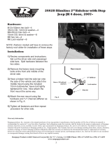
The Rampage™ uses two DMX chan-
nels to operate properly. Channel one
(1) controls the Gobo/Color combination
wheel and channel two (2) controls the
mirror rotation.
1
2
3
4
5
6
7
8
9
10
11
12
13
14
15
16
Rampage Gobo Wheel Layout
©American DJ Supply® www.americandj.com Rampage Instruction Manual Page 10
Channel 1
Gobo 16/Magenta & White
Gobo 15/Pink
Strobe
Fast Strobe
Chasing
270˚
180˚
90˚
0˚
Mirror Rotation
Channel 2
Gobo 14/Baby Blue & Yellow
Gobo 13/Light Green
Gobo 12/Yellow
Gobo 11/Baby Blue
Gobo10/Red
Gobo 9/Quad Color
Gobo 8/Green & Pink
Gobo 6/Pink
Gobo 7/Aqua
Gobo 5/Orange
Gobo 4/Green
Gobo 3 /Blue
Gobo 2/Magenta
Gobo 1/Yellow
White
Blackout
Gobo / Color
Value
170
160
150
140
130
120
110
100
90
80
70
60
50
40
30
10
0
230
227
200
180
Rotation
©American DJ Supply® www.americandj.com Rampage Instruction Manual Page 9

Model: Rampage™
SPECIFICATIONS:
Voltage: 120V / 220V
Lamp: ELC-3 24v / 250w
Dimensions: 12.25” x 5.5” x 11”
Weight: 20 lbs.
Fuse: 5A
Working Position: Any safe position
Cooling: Fan Cooled
Duty Cycle: 30 min. ON, 10 min. OFF
Gobos: 16 / Plus Spot - fixed
Colors: 11 - 4 Split - 1 Multi Color
©American DJ Supply® www.americandj.com Rampage Instruction Manual Page 12
DMX CHANNEL
1 2 3 54 7 9 1086
ON
1 4 16 64 256
2 8 32 128
DMX means Digital Multiplex. This is a universal binary language used to
control intelligent lighting fixtures. Each dip switch number has an ADDRESS
based on binary code:
Dip Switch 1 address equals 1
Dip Switch 2 address equals 2
Dip Switch 3 address equals 4
Dip Switch 4 address equals 8
Dip Switch 5 address equals 16
Dip Switch 6 address equals 32
Dip Switch 7 address equals 64
Dip Switch 8 address equals 128
Dip Switch 9 address equals 256
Dip Switch 10 is used to control the Master/Slave operation. Turning dip
switch 10 on will activate that unit as a “Master Unit.”
DMX Addressing
©American DJ Supply® www.americandj.com Rampage Instruction Manual Page 11
DMX Channel Value
/