Page is loading ...


MM-018336-001, Rev. E
2
MANUAL REVISION HISTORY
REV. DATE REASON FOR CHANGE
D Apr/14
Added CH-100 control head and Unity XG-100M mobile radio. Revised Mobile Radio
Operation section.
E Jul/16 Updated front and back covers.
Harris Corporation, Public Safety and Professional Communications (PSPC) Business, continually evaluates its technical
publications for completeness, technical accuracy, and organization. You can assist in this process by submitting your
comments and suggestions to the following:
Harris Corporation fax your comments to: 1-434-455-6851
PSPC Business or
Technical Publications e-mail us at: PSPC
_
TechPubs
@
harris.com
221 Jefferson Ridge Parkway
Lynchburg, VA 24501
ACKNOWLEDGEMENT
This device is made under license under one or more of the following US patents: 4,590,473; 4,636,791; 5,148,482;
5,185,796; 5,271,017; 5,377,229; 4,716,407; 4,972,460; 5,502,767; 5,146,497; 5,164,986; 5,185,795; 5,226,084; 5,247,579;
5,491,772; 5,517,511; 5,630,011; 5,649,050; 5,701,390; 5,715,365; 5,754,974; 5,826,222; 5,870,405; 6,161,089; and
6,199,037 B1. DVSI claims certain rights, including patent rights under aforementioned U.S. patents, and under other U.S.
and foreign patents and patents pending. Any use of this software or technology requires a separate written license from
DVSI.
CREDITS
Harris, VIDA, OpenSky, and EDACS are registered trademarks and TECHNOLOGY TO CONNECT, INFORM AND
PROTECT are trademarks of Harris Corporation.. All other brand and product names are trademarks, registered trademarks,
or service marks of their respective holders.
NOTICE!
The material contained herein is subject to U.S. export approval. No export or re-export is permitted without written
approval from the U.S. Government. Rated: EAR99 in accordance with U.S. Dept. of Commerce regulations 15CFR774,
Export Administration Regulations.
Information and descriptions contained herein are the property of Harris Corporation. Such information and descriptions may
not be copied or reproduced by any means, or disseminated or distributed without the express prior written permission of
Harris Corporation, PSPC Business, 221 Jefferson Ridge Parkway, Lynchburg, VA 24501.
Repairs to this equipment should be made only by an authorized service technician or facility designated by the supplier. Any
repairs, alterations or substitutions of recommended parts made by the user to this equipment not approved by the
manufacturer could void the user's authority to operate the equipment in addition to the manufacturer's warranty.
This product conforms to the European Union WEEE Directive 2012/19/EU. Do not dispose of this product in
a public landfill. Take it to a recycling center at the end of its life.
Harris products comply with the Restriction of the Use of Certain Hazardous Substances in Electrical and
Electronic Equipment (RoHS) Directive.
This manual is published by
Harris Corporation without any warranty. Im
provements and changes to this manual
necess
i
tated by typographical errors, inaccuracies of current information, or improvements to programs and/or equipment,
may be made by
Harris Corporation at any time and without notice. Such changes will be incorporat
ed into new editions of
this manual. No part of this manual may be reproduced or transmitted in any form or by any means, electronic or mechanical,
including photocopying and recording, for any purpose, without the express written permission of
Harris Corporation.
Copyright© 2010, 2014, 2016, Harris Corporation

MM-018336-001, Rev. E
3
TABLE OF CONTENTS
Section Page
1 REGULATORY AND SAFETY INFORMATION .................................................................... 5
1.1 SAFETY SYMBOL CONVENTIONS ................................................................................................. 5
1.2 RF
ENERGY EXPOSURE AWARENESS AND CONTROL INFORMATION FOR FCC
OCCUPATIONAL USE REQUIREMENTS ........................................................................................ 5
1.2.1 Federal Communications Commission (FCC) Regulations .................................................... 6
1.3 COMPLIANCE
WITH RF EXPOSURE STANDARDS ...................................................................... 6
1.3.1 Mobile Antennas .................................................................................................................... 7
1.3.2 Approved Accessories .......................................................................................................... 12
1.3.3 Contact Information .............................................................................................................. 12
1.4 RADIO
FREQUENCY INTERFERENCE ......................................................................................... 12
1.4.1 FCC Part 15 .......................................................................................................................... 12
1.4.2 Industry Canada .................................................................................................................... 12
1.5 OCCUPATIONAL
SAFETY GUIDELINES AND SAFETY TRAINING INFORMATION ........... 13
1.6 COMMON
HAZARDS ...................................................................................................................... 13
1.7 SAFE
DRIVING RECOMMENDATIONS ........................................................................................ 14
1.8 OPERATING
RULES REGULATIONS ............................................................................................ 14
1.9 OPERATING
TIPS ............................................................................................................................. 15
2 INTRODUCTION ........................................................................................................................ 16
2.1 GENERAL INFORMATION ............................................................................................................. 16
2.2 PRIMARY
OPERATING MODES .................................................................................................... 16
2.2.1 Mobile Radio Mode (Vehicular Repeater Disabled) ............................................................ 16
2.2.2 Extended Coverage (XCOV) Vehicular Repeater Mode ...................................................... 17
2.2.3 Scene-Of-Incident (SOI) Vehicular Repeater Mode ............................................................. 19
2.3 MULTIPLE
ON-SCENE VEHICULAR REPEATERS ..................................................................... 20
2.4 LIMITATIONS
OF THE VRS7000 VEHICULAR REPEATER ....................................................... 21
2.4.1 General Information ............................................................................................................. 21
2.4.2 Limited Feature Set .............................................................................................................. 21
2.4.3 Vehicular Repeater Mode Disables Mobile Radio Mode ..................................................... 21
2.4.4 Loss of P25 Trunked Network Connectivity Disconnects Client Radios Connected via
XCOV Mode ................................................................................................................. 21
2.4.5 One Talk Path ....................................................................................................................... 22
2.4.6 Slight Audio Delay Between Client Radios and Network ....................................................
22
2.
4.7 Other Limitations .................................................................................................................. 23
2.5 CONTROL
HEADS ........................................................................................................................... 24
2.5.1 CH-100 Control Head ........................................................................................................... 24
2.5.2 CH-721 System Model Control Head ................................................................................... 24
3 VEHICULAR REPEATER OPERATION WITH CH-100 CONTROL HEAD ................... 25
3.1 TURNING ON THE VRS7000 ........................................................................................................... 25
3.2 USING
A VEHICULAR REPEATER MODE ................................................................................... 26
3.2.1 Switch to a P25 Radio Zone/System (Required for XCOV Mode Only) ............................. 26
3.2.2 Enable/Disable a Vehicular Repeater Mode via the Control Head’s Menu .......................... 28
3.2.3 Enable/Disable a Vehicular Repeater Mode via External Switch ......................................... 29
3.2.4 Indications During XCOV Mode Operations (CH-100 Control Head) ................................ 30
3.2.5 Indications During SOI Mode Operations (CH-100 Control Head) .................................... 31
4 VEHICULAR REPEATER OPERATION WITH CH-721 CONTROL HEAD ................... 32
4.1 TURNING ON THE VRS7000 ........................................................................................................... 32
4.2 PIN
ENTRY (IF REQUIRED) ............................................................................................................ 33
4.3 USING
A VEHICULAR REPEATER MODE ................................................................................... 33
4.3.1 Switch to a P25 Radio System (Required for XCOV Mode Only ) ..................................... 33
4.3.2 Enable/Disable a Vehicular Repeater Mode via the Control Head’s Menu .......................... 34
4.3.3 Enable/Disable a Vehicular Repeater Mode via Control Head Button (If Programmed) ..... 34

MM-018336-001, Rev. E
4
TABLE OF CONTENTS
Section Page
4.3.4 Enable/Disable a Vehicular Repeater Mode via External Switch ......................................... 35
4.3.5 Indications During XCOV Mode Operations (with CH-721 Control Head) ....................... 36
4.3.6 Indications During SOI Mode Operations (with CH-721 Control Head) ............................. 37
5 MOBILE RADIO OPERATION ................................................................................................ 38
6 CONTROL AND STATUS SERVICES .................................................................................... 38
7 TECHNICAL ASSISTANCE ..................................................................................................... 39
8 CH-721 KEYPAD REMAPPING ............................................................................................... 40
9 RADIO SETUP ............................................................................................................................ 41
LIST OF FIGURES
Page
Figure 2-1: Operational Diagram of Extended Coverage (XCOV) Vehicular Repeater Mode ........... 17
Figure 2-2: Operational Diagram of Scene-Of-Incident (SOI) Vehicular Repeater Mode ................. 19
Figure 3-1: CH-100 Control Head ....................................................................................................... 25
Figure 4-1: CH-721 System Model Control Head ............................................................................... 32
LIST OF TABLES
Page
Table 1-1: Recommended Minimum Safe Lateral Distance from Transmitting Antenna for
Mobile Radio-to-Network Radio Link (VRMS7010/VRMS7020 Transmit/Receive
Antenna) .............................................................................................................................. 7
Table 1-2: Recommended Minimum Safe Lateral Distance from Transmitting Antenna for
Mobile Radio-to-Network Radio Link (50-Watt M7300/XG-75M-based VRMS7030
Transmit/Receive Antenna) ............................................................................................... 10
Table 1-3: Recommended Minimum Safe Lateral Distance from Transmitting Antenna for
Mobile Radio-to-Network Radio Link (110-Watt M7300/XG-75M-based VRMS7030
Transmit/Receive Antenna) ............................................................................................... 10
Table 1-4: Recommended Minimum Safe Lateral Distance from Transmitting Antenna for
Mobile Radio-to-Network Radio Link (Multiband Unity XG-100M-based VRS7030
Transmit/Receive Antenna) ............................................................................................... 11
Table 1-5: Recommended Minimum Safe Lateral Distance from Transmitting Antenna for
Vehicular Repeater-to-Portable Radio Link (VRBS7010/VRBS7020/VRBS7030
Transmit/Receive Antenna) ............................................................................................... 12
Table 5-1: Publication Numbers for Quick Guides and Operator’s Manuals ....................................... 38

MM-018336-001, Rev. E
5
1 REGULATORY AND SAFETY INFORMATION
1.1 SAFETY SYMBOL CONVENTIONS
The following conventions are used in this manual to alert the user to general safety precautions that must
be observed during all phases of operation, service, and repair of this product. Failure to comply with
these precautions or with specific warnings elsewhere violates safety standards of design, manufacture,
and intended use of the product. Harris assumes no liability for the customer's failure to comply with
these standards.
WARNING
The WARNING symbol calls attention to a procedure, practice, or the like, which,
if not correctly performed or adhered to, could result in personal injury. Do not
proceed beyond a WARNING symbol until the conditions identified are fully
understood or met.
CAUTION
The CAUTION symbol calls attention to an operating procedure, practice, or the like,
which, if not performed correctly or adhered to, could result in damage to the
equipment or severely degrade equipment performance.
NOTE
The NOTE symbol calls attention to supplemental information, which may improve
system performance or clarify a process or procedure.
1.2 RF ENERGY EXPOSURE AWARENESS AND CONTROL
INFORMATION FOR FCC OCCUPATIONAL USE REQUIREMENTS
Before using the mobile two-way radio, read this important radio frequency (RF) energy awareness
and control information to ensure compliance with RF exposure guidelines.
WARNING
This radio is intended for use in occupational/controlled conditions, where users
have full knowledge of their exposure and can exercise control over their exposure
to remain below RF exposure limits. This radio is NOT authorized for general
population, consumer, or any other use.
CAUTION
Changes or modifications not expressly approved by Harris
could void the user's
authority to operate the equipment.
This two-way radio uses electromagnetic energy in the radio frequency (RF) spectrum to provide
communications between two or more users over a distance. It uses RF energy or radio waves to send and
receive calls. RF energy is one form of electromagnetic energy. Other forms include, but are not limited
to, electric power, sunlight, and x-rays. RF energy, however, should not be confused with these other
forms of electromagnetic energy, which, when used improperly, can cause biological damage. Very high
levels of x-rays, for example, can damage tissues and genetic material.
Experts in science, engineering, medicine, health, and industry work with organizations to develop stan-
dards for exposure to RF energy. These standards provide recommended levels of RF exposure for both
workers and the general public. These recommended RF exposure levels include substantial margins of
protection. All two-way radios marketed in North America are designed, manufactured, and tested to en-

MM-018336-001, Rev. E
6
sure they meet government-established RF exposure levels. In addition, manufacturers also recommend
specific operating instructions to users of two-way radios. These instructions are important because they
inform users about RF energy exposure and provide simple procedures on how to control it. Please refer
to the following websites for more information on what RF energy exposure is and how to control expo-
sure to assure compliance with established RF exposure limits:
http://www.fcc.gov/oet/rfsafety/rf-faqs.html
http://www.osha.gov./SLTC/radiofrequencyradiation/index.html
1.2.1 Federal Communications Commission (FCC) Regulations
Before it was marketed in the United States, the P25 Vehicular Repeater System was tested to ensure
compliance with FCC RF energy exposure limits for mobile two-way radios. When two-way radios are
used as a consequence of employment, the FCC requires users to be fully aware of and able to control
their exposure to meet occupational requirements. Exposure awareness can be facilitated by the use of a
label directing users to specific user awareness information. The radio has an RF exposure product label.
Also, this manual includes information and operating instructions required to control RF exposure and to
satisfy compliance requirements.
1.3 COMPLIANCE WITH RF EXPOSURE STANDARDS
The P25 Vehicular Repeater System is designed and tested to comply with a number of national and
international standards and guidelines regarding human exposure to RF electromagnetic energy. This
radio complies with the IEEE and ICNIRP exposure limits for occupational/controlled RF exposure
environment at duty-cycle times of up to 50% (50% transmit, 50% receive) for the VRMS radio
equipment, and up to 100% for the VRBS radio equipment. The radio equipment is authorized by the
FCC for occupational use. In terms of measuring RF energy for compliance with the FCC exposure
guidelines, the radio’s antenna radiates measurable RF energy only while it is transmitting (talking), not
when it is receiving (listening), or in standby mode.
The P25 Vehicular Repeater System complies with the following RF energy exposure standards and
guidelines:
• United States Federal Communications Commission (FCC), Code of Federal Regulations; 47 CFR
§ 2 sub-part J.
• American National Standards Institute (ANSI)/Institute of Electrical and Electronic Engineers (IEEE)
C95.1-2005.
• Institute of Electrical and Electronic Engineers (IEEE) C95.1-2005.
• IC Standard RSS-102, Issue 2, 2005: Spectrum Management and Telecommunications Radio
Standards Specification. Radiofrequency Exposure Compliance of Radiocommunication Apparatus
(All Frequency Bands).
CAUTION
Table 1-1 through Table 1-5 list the recommended minimum safe lateral distances for a
controlled environment and for unaware bystanders in an uncontrolled environment,
from transmitting antennas (i.e., monopoles over a ground plane, or dipoles). Table 1-1
through Table 1-4 specify minimum distances for the respective VRMS section of the
vehicular repeater on a per antenna basis. Table 1-5 specifies minimum distances for
the VRBS section of the vehicular repeater on a per antenna basis. This data is based
upon the mobile radio installed in a motor vehicle with the radio transmitting at its
rated RF power level. Transmit only when unaware bystanders are at least the
uncontrolled r
ecommended minimum safe lateral distance away from the mobile
radio’s transmitting antenna.

MM-018336-001, Rev. E
7
1.3.1 Mobile Antennas
The antennas for the radio must be installed in accordance with guidelines and procedures contained in
the Installation and Product Safety Manual. These mobile antenna installation guidelines are limited to
metal body motor vehicles or vehicles with appropriate ground planes. The antenna must be installed in
accordance with:
• The requirements of the antenna manufacturer/supplier included with the antenna.
• Instructions in the Installation and Product Safety Manual, including minimum antenna cable lengths.
The Installation and Product Safety Manual contains specific information on how to install the
antennas to facilitate recommended operating distances to all potentially exposed persons.
Use only the Harris-approved/supplied antenna(s), or an approved replacement antenna. Unauthorized
antennas, modifications, or attachments could damage the radio and may violate FCC regulations.
Table 1-1: Recommended Minimum Safe Lateral Distance
from Transmitting Antenna for Mobile Radio-to-Network Radio Link
(VRMS7010/VRMS7020 Transmit/Receive Antenna)
ANTENNA
PART NUMBER
ANTENNA DESCRIPTION
RECOMMENDED MINIMUM LATERAL HUMAN BODY
DISTANCE FROM TRANSMITTING ANTENNA
CONTROLLED
ENVIRONMENT
UNCONTROLLED
ENVIRONMENT
AN-125001-002
(mount) with
AN-225001-001
(element)
700/800 MHz Standard
Rooftop-Mount;
3 dBd Gain
9.8 Inches
(25 Centimeters)
21.7 Inches
(55 Centimeters)
AN-125001-002
(mount) with
AN-225001-002
(element)
700/800 MHz Standard
Rooftop-Mount;
Elevated-Feed 3 dBd Gain
AN-125001-002
(mount) with
AN-225001-003
(element)
700/800 MHz Standard
Rooftop-Mount;
Elevated-Feed, No Ground Plane
3 dBd Gain
AN-125001-002
(mount) with
AN-225001-004
(element)
700/800 MHz Standard
Rooftop-Mount;
Low-Profile 2 dBd Gain
AN-125001-002
(mount) with
AN-225006-001
(element)
132 to 960 MHz, ¼-Wavelength;
Standard Rooftop-Mount;
0 dBd Gain; Field-Tuned
AN-125001-002
(mount) with
AN-225001-005
(element)
700/800 MHz Standard
Rooftop-Mount;
5 dBd Gain
11.8 Inches
(30 Centimeters)
23.6 Inches
(60 Centimeters)

MM-018336-001, Rev. E
8
Table 1-1: Recommended Minimum Safe Lateral Distance
from Transmitting Antenna for Mobile Radio-to-Network Radio Link
(VRMS7010/VRMS7020 Transmit/Receive Antenna)
ANTENNA
PART NUMBER
ANTENNA DESCRIPTION
RECOMMENDED MINIMUM LATERAL HUMAN BODY
DISTANCE FROM TRANSMITTING ANTENNA
CONTROLLED
ENVIRONMENT
UNCONTROLLED
ENVIRONMENT
AN-125001-004
(mount) with
AN-225001-001
(element)
700/800 MHz Thick
Rooftop-Mount;
3 dBd Gain
9.8 Inches
(25 Centimeters)
21.7 Inches
(55 Centimeters)
AN-125001-004
(mount) with
AN-225001-002
(element)
700/800 MHz Thick
Rooftop-Mount;
Elevated-Feed 3 dBd Gain
AN-125001-004
(mount) with
AN-225001-003
(element)
700/800 MHz Thick
Rooftop-Mount;
Elevated-Feed, No Ground Plane
3 dBd Gain
AN-125001-004
(mount) with
AN-225001-004
(element)
700/800 MHz Thick
Rooftop-Mount;
Low-Profile 2 dBd Gain
AN-125001-004
(mount) with
AN-225006-001
(element)
132 to 960 MHz, ¼-Wavelength;
Thick Rooftop-Mount;
0 dBd Gain; Field-Tuned
AN-125001-004
(mount) with
AN-225001-005
(element)
700/800 MHz Thick
Rooftop-Mount;
5 dBd Gain
11.8 Inches
(30 Centimeters)
23.6 Inches
(60 Centimeters)
AN-125001-006
(mount) with
AN-225001-001
(element)
700/800 MHz GPS Combo
Rooftop-Mount;
3 dBd / 5.15 dBi Gain
9.8 Inches
(25 Centimeters)
21.7 Inches
(55 Centimeters)
AN-125001-006
(mount) with
AN-225001-002
(element)
700/800 MHz GPS Combo
Rooftop-Mount;
Elevated-Feed 3 dBd Gain
AN-125001-006
(mount) with
AN-225001-003
(element)
700/800 MHz GPS Combo
Rooftop-Mount;
Elevated-Feed, No Ground Plane
3 dBd Gain
AN-125001-006
(mount) with
AN-225001-004
(element)
700/800 MHz GPS Combo
Rooftop-Mount;
Low-Profile 2 dBd Gain
AN-125001-006
(mount) with
AN-225006-001
(element)
132 to 960 MHz, ¼-Wavelength;
GPS Combo Rooftop-Mount;
0 dBd Gain; Field-Tuned

MM-018336-001, Rev. E
9
Table 1-1: Recommended Minimum Safe Lateral Distance
from Transmitting Antenna for Mobile Radio-to-Network Radio Link
(VRMS7010/VRMS7020 Transmit/Receive Antenna)
ANTENNA
PART NUMBER
ANTENNA DESCRIPTION
RECOMMENDED MINIMUM LATERAL HUMAN BODY
DISTANCE FROM TRANSMITTING ANTENNA
CONTROLLED
ENVIRONMENT
UNCONTROLLED
ENVIRONMENT
AN-125001-006
(mount) with
AN-225001-005
(element)
700/800 MHz GPS Combo
Rooftop-Mount;
5 dBd / 7.15 dBi Gain
11.8 Inches
(30 Centimeters)
23.6 Inches
(60 Centimeters)
AN-125001-008
(mount) with
AN-225001-001
(element)
700/800 MHz Magnetic-Mount;
3 dBd Gain
9.8 Inches
(25 Centimeters)
21.7 Inches
(55 Centimeters)
AN-125001-008
(mount) with
AN-225001-002
(element)
700/800 MHz Magnetic-Mount;
Elevated-Feed 3 dBd Gain
AN-125001-008
(mount) with
AN-225001-003
(element)
700/800 MHz Magnetic-Mount;
Elevated-Feed, No Ground Plane
3 dBd Gain
AN-125001-008
(mount) with
AN-225001-004
(element)
700/800 MHz Magnetic-Mount;
Low-Profile 2 dBd Gain
AN-125001-008
(mount) with
AN-225006-001
(element)
132 to 960 MHz, ¼-Wavelength;
Standard Rooftop-Mount;
0 dBd Gain; Field-Tuned
9.8 Inches
(25 Centimeters)
21.7 Inches
(55 Centimeters)
AN-125001-008
(mount) with
AN-225001-005
(element)
700/800 MHz Magnetic-Mount;
5 dBd Gain
11.8 Inches
(30 Centimeters)
23.6 Inches
(60 Centimeters)

MM-018336-001, Rev. E
10
Table 1-2: Recommended Minimum Safe Lateral Distance from Transmitting Antenna for Mobile
Radio-to-Network Radio Link (50-Watt M7300/XG-75M-based VRMS7030 Transmit/Receive Antenna)
ANTENNA
ELEMENT
PART NUMBER
ANTENNA ELEMENT
DESCRIPTION
RECOMMENDED MINIMUM LATERAL HUMAN BODY
DISTANCE FROM TRANSMITTING ANTENNA
CONTROLLED
ENVIRONMENT
UNCONTROLLED
ENVIRONMENT
AN-225002-001 136 to 174 MHz, 0 dBd Gain
24.8 Inches
(63 Centimeters)
55.1 Inches
(140 Centimeters)
AN-225006-001 132 to 960 MHz, 0 dBd Gain*
AN-225002-003 136 to 174 MHz, 3 dBd Gain*
35.0 Inches
(89 Centimeters)
78.0 Inches
(198 Centimeters)
AN-225002-004 136 to 174 MHz, 2.4 dBd Gain*
32.7 Inches
(83 Centimeters)
72.8 Inches
(185 Centimeters)
* Element must be trimmed to proper length in order to minimize antenna system VSWR.
Table 1-3: Recommended Minimum Safe Lateral Distance from Transmitting Antenna for Mobile
Radio-to-Network Radio Link (110-Watt M7300/XG-75M-based VRMS7030 Transmit/Receive Antenna)
ANTENNA
ELEMENT
PART NUMBER
ANTENNA ELEMENT
DESCRIPTION
RECOMMENDED MINIMUM LATERAL HUMAN BODY
DISTANCE FROM TRANSMITTING ANTENNA
CONTROLLED
ENVIRONMENT
UNCONTROLLED
ENVIRONMENT
AN-225002-001 136 to 174 MHz, 0 dBd Gain
36.6 Inches
(93 Centimeters)
81.9 Inches
(208 Centimeters)
AN-225006-001 132 to 960 MHz, 0 dBd Gain*
AN-225002-003 136 to 174 MHz, 3 dBd Gain*
52.0 Inches
(132 Centimeters)
115.7 Inches
(294 Centimeters)
AN-225002-004 136 to 174 MHz, 2.4 dBd Gain*
48.4 Inches
(123 Centimeters)
107.9 Inches
(274 Centimeters)
* Element must be trimmed to proper length in order to minimize antenna system VSWR.

MM-018336-001, Rev. E
11
Table 1-4: Recommended Minimum Safe Lateral Distance from Transmitting Antenna for Mobile
Radio-to-Network Radio Link (Multiband Unity XG-100M-based VRS7030 Transmit/Receive Antenna)
RF BAND
ANTENNA
PART NUMBERS
RECOMMENDED MINIMUM LATERAL HUMAN BODY
DISTANCE FROM TRANSMITTING ANTENNA
CONTROLLED
ENVIRONMENT
UNCONTROLLED
ENVIRONMENT
VHF
AN-125001-002 (mount) with
12099-0310-01 (element)
28.3 inches
(72 centimeters)
63.0 inches
(160 centimeters)
AN-125001-004 (mount) with
12099-0310-01 (element)
AN-125001-006 (mount) with
12099-0310-01 (element)
AN-125001-008 (mount) with
12099-0310-01 (element)
AN-125001-002 (mount) with
12099-0330-01 (element)
AN-125001-004 (mount) with
12099-0330-01 (element)
UHF
AN-125001-002 (mount) with
12099-0310-01 (element)
24.4 inches
(62 centimeters)
54.3 inches
(138 centimeters)
AN-125001-004 (mount) with
12099-0310-01 (element)
AN-125001-006 (mount) with
12099-0310-01 (element)
AN-125001-008 (mount) with
12099-0310-01 (element)
AN-125001-002 (mount) with
12099-0330-01 (element)
33.9 inches
(86 centimeters)
75.6 inches
(192 centimeters)
AN-125001-004 (mount) with
12099-0330-01 (element)
700/800 MHz
AN-125001-002 (mount) with
12099-0310-01 (element)
7.9 inches
(20 centimeters)
19.7 inches
(50 centimeters)
AN-125001-004 (mount) with
12099-0310-01 (element)
AN-125001-006 (mount) with
12099-0310-01 (element)
AN-125001-008 (mount) with
12099-0310-01 (element)
AN-125001-002 (mount) with
12099-0330-01 (element)
7.9 inches
(20 centimeters)
24 inches
(61 centimeters)
AN-125001-004 (mount) with
12099-0330-01 (element)

MM-018336-001, Rev. E
12
Table 1-5: Recommended Minimum Safe Lateral Distance
from Transmitting Antenna for Vehicular Repeater-to-Portable Radio Link
(VRBS7010/VRBS7020/VRBS7030 Transmit/Receive Antenna)
ANTENNA
PART NUMBER
ANTENNA DESCRIPTION
RECOMMENDED MINIMUM LATERAL HUMAN
BODY DISTANCE FROM TRANSMITTING ANTENNA
CONTROLLED
ENVIRONMENT
UNCONTROLLED
ENVIRONMENT
AN-125001-002
(mount) with
AN-225001-004
(element)
Standard Rooftop-Mount with Low-
Loss Cable and 700/800 MHz Low-
Profile 2 dBd Gain Element
7.9 Inches
(20 Centimeters)
7.9 Inches
(20 Centimeters)
AN-125001-004
(mount) with
AN-225001-004
(element)
Thick Rooftop-Mount with Low-Loss
Cable and 700/800 MHz Low-
Profile
2 dBd Gain Element
AN-125001-008
(mount) with
AN-225001-004
(element)
Magnetic-Mount with Low-Loss
Cable and 700/800 MHz Low-
Profile
2 dBd Gain Element
1.3.2 Approved Accessories
The radio has been tested and meets FCC RF guidelines when used with accessories supplied or
designated for use with it. Use of other accessories may not ensure compliance with the FCC’s RF
exposure guidelines, and may violate FCC regulations.
For a list of approved accessories refer to the product manuals, the Products and Services Catalog, or
contact Harris Corporation at 1-800-368-3277.
1.3.3 Contact Information
For additional information on exposure requirements or other information, contact Harris Corporation at
1-800-528-7711 or at www.pspc.harris.com.
1.4 RADIO FREQUENCY INTERFERENCE
1.4.1 FCC Part 15
This device complies with Part 15 of the FCC Rules. Operation is subject to the following two conditions:
1. This device may not cause harmful interference, and
2. This device must accept any interference received, including interference that may cause undesired
operation.
1.4.2 Industry Canada
This device complies with Industry Canada license-exempt RSS standard(s). Operation is subject to the
following two conditions: (1) this device may not cause interference, and (2) this device must accept any
interference, including interference that may cause undesired operation of the device.
Le présent appareil est conforme aux CNR d'Industrie Canada applicables aux appareils radio exempts de
licence. L'exploitation est autorisée aux deux conditions suivantes : (1) l'appareil ne doit pas produire de

MM-018336-001, Rev. E
13
brouillage, et (2) l'utilisateur de l'appareil doit accepter tout brouillage radioélectrique subi, même si le
brouillage est susceptible d'en compromettre le fonctionnement.
1.5 OCCUPATIONAL SAFETY GUIDELINES AND SAFETY TRAINING
INFORMATION
To ensure bodily exposure to RF electromagnetic energy is within the FCC allowable limits for
occupational use, always adhere to the following basic guidelines:
• The push-to-talk button should only be depressed when intending to send a voice message.
• The radio should only be used for necessary work-related communications.
• The radio should only be used by authorized and trained personnel. It should never be operated by
children.
• Do not attempt any unauthorized modification to the radio. Changes or modifications to the radio may
cause harmful interference and/or cause it to exceed FCC RF exposure limits. Only qualified
personnel should service the radio.
• Always use only Harris-authorized accessories (antennas, control heads, speakers/mics, etc.). Use of
unauthorized accessories can cause the FCC RF exposure compliance requirements to be exceeded.
The information listed above provides the user with information needed to make him or her aware of a RF
exposure, and what to do to assure that this radio operates within the FCC exposure limits of this radio.
1.6 COMMON HAZARDS
WARNING
The operator of any mobile radio should be aware of certain hazards common to
the operation of vehicular radio transmissions. Possible hazards include but are
not limited to:
• Explosive Atmospheres — Just as it is dangerous to fuel a vehicle with its engine is running, be sure
to turn the radio OFF while fueling the vehicle. If the radio is mounted in the trunk of the vehicle,
DO NOT carry containers of fuel in the trunk.
Areas with potentially explosive atmosphere are often, but not always, clearly marked. Turn the radio
OFF when in any area with a potentially explosive atmosphere. It is rare, but not impossible that the
radio or its accessories could generate sparks.
• Interference To Vehicular Electronic Systems — Electronic fuel injection systems, electronic anti-
skid braking systems, electronic cruise control systems, etc., are typical of the types of electronic
devices that can malfunction due to the lack of protection from radio frequency (RF) energy present
when transmitting. If the vehicle contains such equipment, consult the dealer for the make of vehicle
and enlist his aid in determining if such electronic circuits perform normally when the radio is
transmitting.
• Electric Blasting Caps — To prevent accidental detonation of electric blasting caps, DO NOT use
two-way radios within 1000 feet (305 meters) of blasting operations. Always obey the “Turn Off
Two-Way Radios” (or equivalent) signs posted where electric blasting caps are being used (OSHA
Standard: 1926.900).
• Radio Frequency Energy — To prevent burns or related physical injury from radio frequency
energy, do not operate the transmitter when anyone outside of the vehicle is within the minimum safe
distance from the antenna as specified in Table 1-1 and Table 1-5. Refer to Section 1.2 for additional
information.

MM-018336-001, Rev. E
14
• Vehicles Powered By Liquefied Petroleum (LP) Gas — Radio installation in vehicles powered by
liquefied petroleum gas, where the LP gas container is located in the trunk or other sealed-off space
within the interior of the vehicle, must conform to the National Fire Protection Association standard
NFPA 58. This requires:
The space containing the radio equipment must be isolated and sealed from the space containing
the LP gas container and its fittings.
Outside filling connections must be used for the LP gas container.
The LP gas container space shall be vented to the outside of the vehicle.
• Vehicles Equipped with Airbags — For driver and passenger safety, avoid mounting the radio’s
control head (or any other component) above or near airbag deployment areas. In addition to driver-
side and passenger-side front-impact airbags, some vehicles may also be equipped with side-impact
airbags. For occupant safety, verify the location of all airbags within the vehicle before installing the
radio equipment.
1.7 SAFE DRIVING RECOMMENDATIONS
The American Automobile Association (AAA) advocates the following key safe driving recommenda-
tions:
• Read the literature on the safe operation of the radio.
• Keep both hands on the steering wheel and the microphone in its hanger whenever the vehicle is in
motion.
• Place calls only when the vehicle is stopped.
• When talking from a moving vehicle is unavoidable, drive in the slower lane. Keep conversations
brief.
• If a conversation requires taking notes or complex thought, stop the vehicle in a safe place and
continue the call.
• Whenever using a mobile radio, exercise caution.
1.8 OPERATING RULES REGULATIONS
Two-way radio systems must be operated in accordance with the rules and regulations of the local,
regional, or national government.
In the United States, the P25 Vehicular Repeater System must be operated in accordance with the rules
and regulations of the Federal Communications Commission (FCC). Operators of two-way radio
equipment, must be thoroughly familiar with the rules that apply to the particular type of radio operation.
Following these rules helps eliminate confusion, assures the most efficient use of the existing radio
channels, and results in a smoothly functioning radio network.
When using a two-way radio, remember these rules:
• It is a violation of FCC rules to interrupt any distress or emergency message. The radio operates in
much the same way as a telephone “party line.” Therefore, always listen to make sure the channel is
clear before transmitting. Emergency calls have priority over all other messages. If someone is
sending an emergency message – such as reporting a fire or asking for help in an accident, do not
transmit unless assistance can be offered.
• The use of profane or obscene language is prohibited by Federal law.

MM-018336-001, Rev. E
15
• It is against the law to send false call letters or false distress or emergency messages. The FCC
requires keeping conversations brief and confined to business. Use coded messages whenever
possible to save on-the-air time.
• Using the radio to send personal messages (except in an emergency) is a violation of FCC rules. Send
only essential messages.
• It is against Federal law to repeat or otherwise make known anything overheard on the radio.
Conversations between others sharing the channel must be regarded as confidential.
• The FCC requires self-identification at certain specific times by means of call letters. Refer to the
rules that apply to the particular type of operation for the proper procedure.
• No changes or adjustments shall be made to the equipment except by an authorized or certified
electronics technician.
CAUTION
Under U.S. law, operation of an unlicensed radio transmitter within the jurisdiction of
the United States may be punishable by a fine of up to $10,000, imprisonment for up to
two (2) years, or both.
1.9 OPERATING TIPS
The following conditions tend to reduce the effective range of two-way radios and should be avoided
whenever possible:
• Operating the radio in areas of low terrain, or while under power lines or bridges.
• Obstructions such as mountains and buildings.
NOTE
In areas where transmission or reception is poor, communication improvement may
sometimes be obtained by moving a few yards in another direction, or moving to a
higher elevation.

MM-018336-001, Rev. E
16
2 INTRODUCTION
2.1 GENERAL INFORMATION
The VRS7000 series of Project 25 (P25) vehicular repeaters includes the three (3) distinctly different P25
Vehicular Repeater Systems: the VRS7010, the VRS7020, and the VRS7030. Additionally, the VRS7030
vehicular repeater has three sub-types based upon the mobile radio which it is equipped with. Unless
otherwise stated, operating procedures presented in this manual apply to all in the series. Each repeater
has different radio frequency bands upon which it operates on. The bands are presented in Figure 2-1 on
page 17 and in
Figure 2-2 on page 19.
NOTE
From this point forward, any reference of “VRS7000” in this manual applies to all P25
vehicular repeater systems, unless otherwise stated.
The VRS7000 vehicular repeater has three (3) primary operating modes. First, it can function as a
standard mobile radio for P25 trunked and P25 conventional radio networks. This mode of operation is
called the “mobile radio mode.” In the mobile radio mode, the vehicular repeater section of the VRS7000
is essentially disabled. Second, the VRS7000 can function as a vehicular repeater in a P25 conventional or
a P25 trunked radio network. This mode of operation is called the “Extended Coverage vehicular repeater
mode” or “extended coverage mode” or simply “XCOV” for short. Third, it can function as an
independent off-the-network P25 base station where other radios can connect to it. This vehicular repeater
mode of operation is called the “Scene-Of-Incident mode” or simply “SOI” for short.
The VRS7000 cannot operate as a vehicular repeater when it is operating as a mobile radio (i.e., in the
mobile radio mode). Likewise, it cannot operate as a mobile radio when it is operating as a vehicular
repeater.
NOTE
Vehicular repeater mode operations on a P25 conventional network require XGP radio
firmware. Refer to the respective NOTE on page 17 for additional information. ECP
radio firmware does not
support vehicular repeater operations on P25 conventional
networks. Also, the Scene-Of-
Incident vehicular repeater mode is only available in
XGP radio firmware. Consult with your radio system’s network administration person-
nel for additional information.
NOTE
As of the publication of this manual, only Harris-made P25 trunked radios can connect
to (i.e., be “clients” of) a VRS7000 vehicular repeater
when it is operating as a
vehicular repeater.
The VRS7000 consists of two (2) mobile radio systems coupled together with specialized interface
hardware. As illustrated in Figure 2-1 on page 17, its Vehicular Repeater Mobile System (VRMS)
provides the radio frequency (RF) link to the radio network, and the Vehicular Repeater Base System
(VRBS) provides the RF link for nearby P25 radios. A control head, microphone speaker, and two (2)
antennas complete the radio installation.
2.2 PRIMARY OPERATING MODES
2.2.1 Mobile Radio Mode (Vehicular Repeater Disabled)
The VRS7000 operates like a normal mobile radio when its vehicular repeater mode is disabled. When in
the mobile radio mode, the VRS7000 operates on and provides communications via a P25 trunked, a P25
conventional, or an analog conventional radio network. The type of radio network is determined by the

MM-018336-001, Rev. E
17
“system” selected by the radio operator. Radio control and voice communications are accomplished via
the radio’s control head, the “push-to-talk” (PTT) type microphone, and the speaker connected to the
control head. Using the control head, microphone and speaker, the radio user/operator can control the
radio and communicate with other radio users and console dispatchers in the radio network.
In this mode, nearby radio users can only communicate with the VRS7000 radio user/operator if they can
also directly access the same radio network and/or radio channels/frequencies. Since the vehicular
repeater functionality of the VRS7000 is completely disabled in the mobile radio mode, nearby radios
cannot link through the VRS7000 to the radio network.
NOTE
Refer to Section 5 of this manual (page 38
) for information about the Operator’s
Manuals that describe using the VRS7000 in the mobile radio mode.
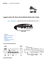
2.2.2 Extended Coverage (XCOV) Vehicular Repeater Mode
When the VRS7000 is operating in the extended coverage vehicular repeater mode, it provides the
network extension that enables nearby P25 radios operating on a vehicular repeater radio frequency
channel to access a P25 radio network. This mode of operation is sometimes abbreviated “vehicular
repeater mode” or simply “XCOV mode.” As illustrated in Figure 2-1, portable radio coverage is
extended due to the VRS7000’s high-performance mobile antenna system and higher transmitter output
power used to access the P25 radio network. In this mode, the VRS7000 can significantly enhance in-
building penetration for P25 portable radios that can operate on the same radio frequency band as the
vehicular repeater. Typical operational scenarios include in-building tactical operations, joint training
exercises, and search-and-rescue operations in remote (i.e., RF-fringe-area) areas.
NOTE
The XCOV vehicular repeater mode can only function when the VRS7000 is operating
on a P25 trunked radio network if the VRS7000 has XGP Release R1A radio firmware
or ECP Release R11A (or later) radio firmware
. Consult with your radio system’s
network administration personnel for details.
The XCOV vehicular repeater mode can function when the VRS7000 is operating on
either a P25 trunked or a P25 conventional radio network if the VRS7000 has XGP
Release R2A (or later) radio firmware.
P25 Vehicular Repeater System
Nearby Harris
P25 Radios
(e.g., P7200 and
P7300 Portable
Radios)
P25 Radio Network RF Link
VRBS
(VRBS7010: 700 MHz)
(
VRBS7020: 800 MHz)
(VRBS7030: 700/800 MHz)
Client Radio-to-Vehicular Repeater
RF Links
Vehicle-Mounted
Antenna
Vehicle-Mounted
Antenna
VRMS
(VRMS7010: 800 MHz)
(VRMS7020: 700 MHz)
(VRMS7030: VHF)
P25 Base
Station
Speaker
Microphone
P25
Client
Radio
P25
Client
Radio
P25
Client
Radio
Control Head
(CH-721 System Model shown)
Figure 2-1: Operational Diagram of Extended Coverage (XCOV) Vehicular Repeater Mode

MM-018336-001, Rev. E
18
When a nearby P25 radio is communicating through the VRS7000, it is considered “connected” to or a
“client” on the VRS7000. The VRS7000 cannot function as a standard/normal mobile radio when it is
operating in the XCOV vehicular repeater mode. Instructions on enabling and disabling this VRS7000
mode are included in Section 4 of this manual.
P25 radio users connect to a VRS7000 by manually making a “system” (aka., “zone”) change at the radio
to connect to an active VRS7000 vehicular repeater. After selecting a zone/system allocated for VRS7000
vehicular repeater operation, the radio then scans for an active vehicular repeater channel. Vehicular
repeater channels are pre-programmed into each P25 radio requiring operation on a VRS7000. For P25
trunked networks, a P25 radio can only connect to a VRS7000 if the radio is registered for
communications on the respective P25 trunked radio network.
After a P25 radio initially connects to a VRS7000, “REGISTER” briefly appears in the radio’s display.
This indicates the radio is registered on the P25 radio network via the VRS7000. Therefore, the radio can
be used to communicate with other radio users on the radio network and with radios connected to the
VRS7000.
The VRS7000 operator can place the VRS7000 into the XCOV vehicular repeater mode via a menu
selection or preset button press at the radio’s control head. Likewise, the operator can disable this mode
via a control head menu selection or preset button press. Alternately, the VRS7000 radio installation may
be wired so this mode can be enabled and disabled by an external switch located on the vehicle’s dash
panel, console panel, or elsewhere.
When the VRS7000 is operating in the XCOV vehicular repeater mode, it functions like a Voice and Data
Over Control (VDOC) site for the nearby P25 radios connected to it. Essentially, the P25 client radios and
the VRBS7000 are linked together via P25 VDOC protocols on the VRBS7000’s VDOC RF channel. If
properly programmed, both P25 portable and P25 mobile radios can connect to the VRS7000 when it is
operating in the XCOV vehicular repeater mode.
For the XCOV vehicular repeater mode, P25 radios operating through the VRS7000 (i.e., “P25 client
radios”) maintain the following functions across the two RF links:
• P25 Group Call — P25 radios connected to the VRS7000 can communicate on a common talk
group, or on multiple different talk groups. When it is operating in the XCOV vehicular repeater
mode, the VRS7000 provides up to sixty-four (64) talk groups (i.e., a different talk group selected at
each radio). Digital clear voice and digital encrypted voice group calls are supported.
• P25 Individual Call — Unit-to-unit calls between two P25 client radios and between a P25 client
radio and a radio/console on the P25 radio network are supported. Digital clear voice and digital
encrypted voice individual calls are supported.
• P25 User ID — Caller identification information is sent between a P25 client radio and the P25radio
network.
• P25 Emergency — The link through the VRS7000 provides P25 emergency communications
between the P25 client radios and the P25radio network.
• P25 System All Call (from Network Only) — A system-wide all-call transmission from the P25
radio network is forwarded to P25 client radios.
• Call Grant and Call Queued Tones — A P25 client radio generates call grant and call queued tones
in a similar manner as if it is operating directly on the P25 radio network.
• Request Status Message (RSM) — An RSM message can be sent from a P25 client radio connected
to a VRS7000 operating in XCOV mode to dispatch consoles in the P25 radio network. This feature
is available in radio firmware XGP Release R1A and later.

MM-018336-001, Rev. E
19
• Status Updates — Real-time status update messages can be sent from a P25 client radio connected to
a VRS7000 operating in XCOV mode to the P25 radio network.
• Request-To-Talk (RTT) and Emergency Request-To-Talk (ERTT) — An RTT/ERTT message
can be sent from a P25 client radio through the VRS7000 to dispatch consoles in the P25 radio
network. This feature is available in radio firmware XGP Release R1A and later, and radio firmware
ECP Release R15A and later.
Up to sixty-four (64) P25 radios can connect to a VRS7000 when it is in XCOV mode. These radio users
can communicate via the same talk group or via multiple different talk groups. Although up to sixty-four
(64) talk groups can be used by connected radios (i.e., a different talk group selected at each radio),
excessive call queuing can result when multiple talk groups and/or individual calls are utilized by the P25
client radios. Refer to Section 2.4.5 on page 22 for additional information.
When operating in the extended coverage (XCOV) vehicular repeater mode, calls transmitted from the
P25 client radios are not routed to the VRS7000’s speaker. Refer to Section 2.4.3 on page 21 for
additional information.
The VRS7000 supports end-to-end Advanced Encryption Standard (AES) encrypted calls. If a P25 client
radio is transmitting an encrypted call, the VRS7000 simply repeats the call to the network base station. It
does not un-encrypt and then re-encrypt the call.
2.2.3 Scene-Of-Incident (SOI) Vehicular Repeater Mode
The Scene-Of-Incident (SOI) vehicular repeater mode enables nearby P25 radios operating on a vehicular
repeater radio frequency channel the ability to communicate with each other using the VRS7000 as a base
station. This mode is advantageous for use during any operational scenario where network communica-
tions (including communications with console dispatchers) is not required and/or not possible. It does not
provide access to any P25 radio network, trunked or conventional. An operational diagram is shown in
Figure 2-2.
P25 Vehicular Repeater System
Nearby Harris
P25 Radios
VRBS
(VRBS7010: 700 MHz)
(VRBS7020: 800 MHz)
(VRBS7030: 700/800 MHz)
Client Radio-to-Vehicular Repeater
RF Links
Vehicle-Mounted
Antenna
Vehicle-Mounted
Antenna (Not Used
in This Mode)
VRMS
(VRMS7010: 800 MHz)
(VRMS7020: 700 MHz)
(VRMS7030: VHF)
Control Head
(CH-721 System Model shown)
Speaker
Microphone
P25
Client
Radio
P25
Client
Radio
P25
Client
Radio
P25
Client
Radio
P25
Client
Radio
Figure 2-2: Operational Diagram of Scene-Of-Incident (SOI) Vehicular Repeater Mode

MM-018336-001, Rev. E
20
P25 radios operating on the VRS7000 (i.e., “P25 client radios”) via SOI vehicular repeater mode maintain
the following basic radio communication functions:
• P25 Group Call — P25 radios connected to the VRS7000 can communicate on a common talk
group, or on multiple different talk groups. Up to sixty-four (64) talk groups are supported (i.e., each
radio can have a different talk group selected). Digital clear voice and digital encrypted voice group
calls are supported.
• P25 Individual Call — The SOI mode supports unit-to-unit calls between two P25 client radios.
Digital clear voice and digital encrypted voice individual calls are supported.
• P25 Emergency — The link through the VRS7000 provides P25 emergency communications
between the P25 client radios.
• Call Grant and Call Queued Tones — A P25 client radio generates call grant and call queued tones
in a similar manner as if it is operating directly on the P25 radio network.
Like the XCOV mode described in the previous section, the SOI vehicular repeater mode allows up to
sixty-four (64) P25 radios to connect to a VRS7000, and these radio users can communicate via the same
talk group or via multiple different talk groups. Although up to sixty-four (64) talk groups can be used by
connected radios in this mode (i.e., a different talk group selected at each radio), excessive call queuing
can result when multiple talk groups and/or individual calls are utilized by the P25 client radios.
CAUTION
The VRS7000 vehicular repeater has only one (1) talk path. Therefore, it is
recommended that all radio users operate on the same talk group. Refer to Section
2.4.5 on page 22 for additional information.
When operating in the SOI vehicular repeater mode, calls transmitted from the P25 client radios are not
routed to the VRS7000’s speaker. Refer to Section 2.4.3 on page 21 for additional information.
The VRS7000’s SOI mode supports end-to-end Advanced Encryption Standard (AES) encrypted calls. If
a P25 client radio is transmitting an encrypted call, the VRS7000 simply repeats the call to the other
radio(s). The VRS7000 does not un-encrypt and then re-encrypt the call.
2.3 MULTIPLE ON-SCENE VEHICULAR REPEATERS
The VRS7000 P25 Vehicular Repeater System design supports multiple on-scene VRS7000s via multiple
radio frequency channels assigned for system-wide vehicular repeater use. When a vehicular repeater
mode is enabled at a particular VRS7000, the VRS7000 automatically selects an unused pre-programmed
channel allocated for vehicular repeater operations after a scanning algorithm determines the channel is
available.
NOTE
Vehicles equipped with a VRS7000 must maintain an antenna separation distance of at
least ten (10) feet during vehicular repeater operations.
When multiple VRS7000s are on a scene, a P25 radio user must manually make a “system” (aka., “zone”)
change to connect to a VRS7000. Subsequently, the P25 radio will scan for and, if properly registered,
connect to an available VRS7000 operating in a vehicular repeater mode. For P25 trunked networks, a
P25 radio can only connect to a VRS7000 if the VRS7000 is registered for communications on the
respective P25 trunked radio network.
VRS7000s in the network can be configured so when a VRS7000 leaves a scene, P25 client radios
connected to it will automatically transition to a second on-scene VRS7000. This automatic hand-off
operation requires proper vehicular repeater channel/frequency configuration in all VRS7000s and P25
/