Page is loading ...

Coolline
Model
CLH301/400/600
Instruction Manual
- Second Edition -
Yamato Scientific Co. LTD.
z Thank you for purchasing "Coolline, CLH Series"
of Yamato Scientific Co., Ltd.
z To use this unit properly, read this "Instruction
Manual" thoroughly before using this unit.
Keep this instruction manual around this unit for
referring at anytime.
WARNING!:
Carefully read and thoroughly understand the
important warning items described in this
manual before usin
g
this unit.

Contents
Cautions in Using with Safety................................................................1
•
Explanation.................................................................................................................... 1
•
Table of Illustrated Symbols .......................................................................................... 2
•
Fundamental Matters of "WARNING!" and "CAUTION!"............................................... 3
Before Using This Unit ...........................................................................4
•
Requirements for Installation......................................................................................... 4
•
Installation Procedure.................................................................................................... 7
Description and Function of Each Part.................................................9
•
Main Unit .......................................................................................................................9
Description and Function of Each Part...............................................10
•
Control Panel............................................................................................................... 10
•
Operation Monitor........................................................................................................ 11
•
Characters of the Controller ........................................................................................ 12
Operation Method .................................................................................13
•
Operation Mode and Function List .............................................................................. 13
•
Operation Mode, Function Setting Key, and Characters ............................................. 15
•
Setting of Overheating Prevention Device .................................................................. 16
•
Fixed Temperature Operation...................................................................................... 17
•
Quick Auto Stop Operation .......................................................................................... 19
•
Auto Stop Operation.................................................................................................... 21
•
Auto Start Operation.................................................................................................... 23
•
Calibration Offset Function.......................................................................................... 25
•
Lock Function.............................................................................................................. 26
•
Temperature Output Terminal...................................................................................... 27
•
RS485 Communication Function................................................................................. 29
•
Cooling curve, cooling capacity curve (reference data)............................................... 41
•
Nybrine freezing temperature and viscosity (reference data)...................................... 45
Handling Precautions ...........................................................................46
Maintenance Method.............................................................................48
•
Daily Inspection and Maintenance .............................................................................. 48
Long storage and disposal...................................................................50
•
When not using this unit for long term / When disposing ............................................ 50
In the Event of Failure….......................................................................51
•
Safety Device and Error Code..................................................................................... 51
•
Trouble Shooting ......................................................................................................... 52
After Service and Warranty ..................................................................53
Specification..........................................................................................54

Wiring Diagram......................................................................................55
•
CLH300 ....................................................................................................................... 55
•
CLH400 ....................................................................................................................... 56
•
CLH600 ....................................................................................................................... 57
Replacement Parts Table......................................................................58
Reference...............................................................................................60
•
List of Dangerous Substances .................................................................................... 60
Installation Standard Manual................................................................61

1
Cautions in Using with Safety
Explanation
MEANING OF ILLUSTRATED SYMBOLS
Various symbols are used in this safety manual in order to use the unit without
danger of injury and damage of the unit. A list of problems caused by ignoring
the warnings and improper handling is divided as shown below.Be sure that you
understand the warnings and cautions in this manual before operating the unit.
WARNING!
If the warning is ignored, there is the danger of a problem that
may cause a serious accident or even fatality.
CAUTION!
If the caution is ignored, there is the danger of a problem that may
cause injury/damage to property or the unit itself.
Meaning of Symbols
This symbol indicates items that urge the warning (including the caution).
A detailed warning message is shown adjacent to the symbol.
This symbol indicates items that are strictly prohibited.
A detailed message is shown adjacent to the symbol with specific actions not to
perform.
This symbol indicates items that should be always performed.
A detailed message with instructions is shown adjacent to the symbol.
Illustrated Symbols

2
Cautions in Using with Safety
Table of Illustrated Symbols
Warning
Warning,
generally
Warning,
high voltage
Warning,
high temperature
Warning,
drive train
Warning,
explosive
Caution
Caution,
generally
Caution,
electrical shock
Caution,
scald
Caution,
no road heating
Caution,
not to drench
Caution,
water only
Caution,
deadly poison
Prohibit
Prohibit,
generally
Prohibit,
inflammable
Prohibit,
to disassemble
Prohibit,
to touch
Compulsion
Compulsion,
generally
Compulsion,
connect to the
grounding
terminal
Compulsion,
install on a flat
surface
Compulsion,
disconnect the
power plug
Compulsion,
periodical
inspection

3
Cautions in Using with Safety
Fundamental Matters of "WARNING!" and "CAUTION!"
WARNING!
Do not use this unit in an area where there is flammable or explosive gas
Never use this unit in an area where there is flammable or explosive gas. This unit is not
explosion-proof. An arc may be generated when the power switch is turned on or off, and
fire/explosion may result. (Refer to page 60 "List of Dangerous Substances".)
Always ground this unit
Always ground this unit on the power equipment side in order to avoid electrical shock due to a power
surge.
If a problem occurs
If smoke or strange odor should come out of this unit for some reason, turn off the circuit breaker right
away, and then disconnect the power plug. Immediately contact a service technician for inspection. If
this procedure is not followed, fire or electrical shock may result. Never perform repair work yourself,
since it is dangerous and not recommended.
Do not use the power cord if it is bundled or tangled
Do not use the power cord if it is bundled or tangled. If it is used in this manner, it can overheat and
fire may be caused.
Do not process, bend, wring, or stretch the power cord forcibly
Do not process, bend, wring, or stretch the power cord forcibly. Fire or electrical shock may result.
Substances that can not be used
Never use explosive substances, flammable substances and substances that include explosive or
flammable ingredients in this unit. Explosion or fire may occur. (Refer to page 60 "List of Dangerous
Substances".)
Do not disassemble or modify this unit
Do not disassemble or modify this unit. Fire or electrical shock or failure may be caused.
Do not touch high-temperature parts
The inside of the body or the door may become hot during and just after operation. It may cause burns.
CAUTION!
During a thunder storm
During a thunderstorm, turn off the power key immediately, then turn off the circuit breaker and the main
power. If this procedure is not followed, fire or electrical shock may be caused.

4
Before Using This Unit
Requirements for Installation
1. Always ground this unit
• Be sure to connect the earth wire (the green cable of power cord) to the grounding conductor
or ground terminal to prevent accidents caused by electric leakage.
• Do not connect the earth wire to gas or water pipes. If not, fire disaster may be caused.
• Do not connect the earth wire to the ground for telephone wire or lightning conductor. If not,
fire disaster or electric shock may be caused.
• Do not use a branching receptacle, which may cause the heat generation.
2. Choose a proper place for installation
• Do not install this unit in a place where:
♦ Rough or dirty surface.
♦ Flammable gas or corrosive gas is generated.
♦ Ambient temperature bellow 5℃ or above 30°C.
♦ Ambient temperature fluctuates violently.
♦ There is direct sunlight.
♦ There is excessive humidity and dust.
♦ There is a constant vibration.
♦ Winds from the air conditioner, etc. hit the sample container directly.
• Install this unit on a stable place with the space as shown below.
More than
20cm
More than
20cm
More than 20cm
More than 20cm
Main Unit
3. Do not use this unit in an area where there is flammable or explosive gas
• Never use this unit in an area where
there is flammable or explosive gas.
This unit is not explosion-proof. An arc
may be generated when the power
switch is turned ON or OFF, and
fire/explosion may result.
• To know about flammable or explosive
gas, refer to page60 “List of Dangerous
Substances”.
爆発性ガス

5
Before Using This Unit
Requirements for Installation
4. Do not modify
• Modification of this unit is strictly prohibited.
This could cause a failure.
5. Installation on horizontal surface
• Place this unit as flat a place as possible. If
the rubber feet (model CLH301) or casters
(models CLH400/600) are not in uniform
contact with the floor surface, noise or
vibration may result. Additionally, the unit
may cause a problem or malfunction.
6. Choose a correct power distribution board or receptacle
• Choose a correct power distribution board or receptacle that meets the unit’s rated electric
capacity.
Electric capacity:
CLH301: 100V AC, 12A
CLH400: 100V AC, 15A
CLH600: 100V AC, 25A
NOTE)
There could be the case that the unit does not run even after turning ON the power. Inspect
whether the voltage of the main power is lowered than the specified value, or whether other
device(s) uses the same power line of this unit. If the phenomena might be found, change the
power line of this unit to the other power line.
7. Before/after installing
• It may cause injure to a person if this unit falls down or moves by the earthquake and the
impact. etc..To prevent, take measures that the unit cannot fall down, and not install to busy
place.
改造
Modification

6
Before Using This Unit
Requirements for Installation
8. Handling of power code
• Do not entangle the power cord. This will cause overheating and possibly a fire.
• Do not bend or twist the power cord, or apply excessive tension to it. This may cause a fire
and electrical shock.
• Do not lay the power cord under a desk or chair, and do not allow it to be pinched in order to
prevent it from being damaged and to avoid a fire or electrical shock.
• Keep the power cord away from any heating equipment such as a room heater. The cord's
insulation may melt and cause a fire or electrical shock.
• If the power cord becomes damaged (wiring exposed, breakage, etc.), immediately turn off the
power at the rear of this unit and shut off the main supply power. Then contact your nearest
dealer for replacement of the power cord. Leaving it may cause a fire or electrical shock.
• Connect the power plug to the receptacle which is supplied appropriate power and voltage.
9. Use a proper circulating fluid in response to working conditions
• Select a circulating fluid according to the working temperature.
Set temperature + 10°C or over: Water
Set temperature + 10°C or below: Antifreezing fluid (Nybrine
®
- 60%, ethylene glycol - 50%)
If water is used at the set temperature of + 10°C or below, the cooling coil may freeze to cause
malfunction.
10. When using a Nybrine aqueous solution instead of water
• The freezing point of the antifreezing fluid depends on its concentration or type. Use an
antifreezing fluid having a 10°C lower at least than the working temperature. Any antifreezing
fluid, which freezes at a higher temperature than that, may freeze in the cooling unit and
deteriorates heat exchanging efficiency.
11. Do not use fluids other than water and antifreezing fluids (Nybrine
®
, ethylene glycol)
• Pour distilled water or tap water into the water tank. Water of poor quality may cause fur or
scale to accumulate on the heater pump, which may result in deteriorated performance or
malfunction (e.g. well water, etc.).
• A circulating fluid with high specific gravity or highly viscosity places overburden on the
circulating pump and damages the unit (e.g. Fluorinert, Galden, etc.).
• A corrosive fluid or a fluid that produces corrosive substances when heated may cause
malfunction (e.g. Fluorinert).
• Do not use any fluid whose vapor is toxic or hazardous because it may result in an accident
(methyl alcohol, etc.).

7
Before Using This Unit
Installation Procedure
1 Release the stopper lock of the casters.
(CLH400/600)
Push down the stopper button of the casters as
shown in the right figure. It will be unlocked.
(Only the two casters on the front side of the unit
are equipped with a caster.)
The model CLH301 is equipped with rubber feet.
2 Move the unit to the place of installation.
If there is a bump on the floor, the casters may receive excessive load and get damaged. In this
case, lift and move the unit.
3 After the unit is placed in the desired position, lock the stopper button of the casters.
4 Check the drain cock.
Confirm that the drain cock on the right side of
the unit is in the "Close" position (perpendicular
to the cock).
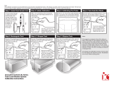
5 Connect the hoses.
• Securely connect the hoses to the ports of the unit and the external water tank of the external
open system so that the fluid does not leak. See the figure shown below. The outside
diameter of both discharge (OUT) and return (IN) ports is each 13 mm.
Note) Connect the priming pump port (IN) to the return (IN) port of the unit.
• Using a solenoid or throttle valve to shut off the circulating path may result in malfunction of the
circulating pump or fluid leakage.
• Do not throttle the path excessively. Keep a flow rate of the circulating fluid at 1.5·/min or over.
• Slowly change the flow rate. A rapid change in the flow rate may reduce the service life of the
circulating pump.
ボタン位置(高)
ロック状態(据付)
ボタン位置(低)
プッシュでロック解除
(移動可)
キャスター
Button position: high
Button position: low
Locked
(during installation)
Push to unlock the
caster (movable)
Caster
閉 運転時の位置
排水時の位置
開
Position during operation
Close
Open
Position durin
g
drainin
g
外部水槽
本 体
吐出口
IN
(OUT)
戻り口
(IN)
OUT
IN
呼び水ポンプ付
断熱ホース
断熱ホース
呼び水ポンプ
CLH unit
Discharge
(OUT)
Return
(IN)
External water tank
Priming pump
Insulation hose with
a priming pump
Insulation hose

8
Before Using This Unit
Installation Procedure
6 Connecting the power.
Confirm that the leakage breaker and the power switch are turned "off," and then plug into an outlet.
7 Installing the external water tank (optional accessory)
Install the external water tank in a higher place than the unit. If it is installed in a lower place, the
flow rate may drop or air bleeding may not be carried out smoothly when pouring the circulating fluid
for the first time.
8 Pour the circulating fluid into the water tank.
• Remove the lid from the external water tank, and pour the circulating fluid.
(Select a circulating fluid in response to the set temperature condition.)
• Open the air release valve cock.
• Push the priming pump more than ten times.
(Feed the fluid from the external water tank to the circulating pump inside the unit to let out air
from the pump. The fluid circulates after air is let out.)
• Turn on the leakage breaker and the power switch. (The circulating fluid flows into the fluid tank
of the unit.)
• After the fluid tank is filled with the fluid, it is discharged into the external water tank. (If the
circulating fluid still does not circulate, immediately turn off the leakage breaker and the power
switch. Check the unit according to the procedure described on page 54.
• Close the air release valve cock.
The circulating pump may malfunction if the unit is operated with the circulating fluid
uncirculated.
• After the circulation of the circulating fluid is stabilized, resupply the circulating fluid to 80% level
of the external water tank.
• After the resupply of the circulating fluid is completed, turn "off" the leakage breaker.
• Replace the lid on the external water tank.
Exercise care not to allow the circulating fluid to get on the unit.If it gets on any electric
part, leakage or electric shock may result.If it splashes on the operation panel, wipe it out.

9
Description and Function of Each Part
Main Unit
Rear view
Front view
Control panel
Drain cock
Earth leakage breaker
Caster
(Two front casters have stopper)
Power switch
Rating notice sticker
Air release valve
Discharge port (OUT)
Power cord
Temperature output terminal
(RS485 communication function)
Return port (IN)

10
Description and Function of Each Part
Control Panel
No. Name Function
① RUN/STOP Key:
Starts/stops the operation.
② ▲▼ Key:
Uses for rising UP/lowering DOWN the setting value.
③ SUB MENU Key:
Uses for setting the overheating prevention temperature, calibration
offset temperature, or key lock function.
④ ENTER Key:
Settles the inputted value.
⑤ FIXED TEMP Key:
Chooses the fixed temperature operation.
⑥ TIMER Key:
Chooses the timer operation (Quick Auto Stop/Auto Stop/Auto Start).
⑦ HEATER Lamp:
Lights while the heater works.
⑧ ALARM Lamp:
Lights up when an error occurs. (Buzzer sounds simultaneously.)
⑨ AUTO STOP Lamp:
Blinks while setting quick auto stop timer or auto stop timer.
Lights while quick auto stop timer or auto stop timer is running.
⑩ AUTO START Lamp:
Blinks while setting auto start timer.
Lights while auto start timer is running.
⑪ FIXED TEMP Lamp:
Blinks while setting fixed temperature operation.
Lights while fixed temperature operation is running.
⑫
Measurement Temperature
Display:
Displays the measured temperature, setting character, alarm
information.
⑬
Setting Temperature
Display:
Displays the setting temperature, setting value for timer mode,
remaining time.
⑭
Overheating Prevention
Temperature Display:
Displays the setting temperature for overheating prevention device.
⑮ Operation Monitor:
Refer to page 11.
⑦
⑧
⑨
⑩
⑪
④
⑤
⑥
⑮
②
③
①
⑭
⑬
⑫

11
Description and Function of Each Part
Operation Monitor
No. Name Function
①
Refrigerator Error Lamp Lights when the refrigerator is overloaded.
②
Error Lamp Lights when the flow rate of the cooling water has dropped.
③
Refrigerator Lamp Lights when the refrigerator is in operation.
④
Pump Lamp Lights when the pump is in operation.
① ③
② ④

12
Description and Function of Each Part
Characters of the Controller
The characters controller shows are as follows:
Character Identifier Name Purpose
FiX
Fixed Temperature
Setting Mode
Used for setting the fixed temperature
operation.
Sv
Temperature Setting
Used for setting the temperature.
AStP
Auto Stop Setting
Used for setting the auto stop operation.
AStr
Auto Start Setting
Used for setting the auto start operation.
tim
Time Setting
Used for setting the time.
End
Time-up
Displayed when timer operation is ended.
cAL
Calibration Offset
Setting
Used for inputting the calibration offset
temperature. (Refer to Page 25 "Calibration
Offset Function".)
oH
Overheating
Prevention Setting
Used for setting temperature for overheating
prevention device. (Refer to Page 16 "Setting of
Overheating Prevention Device ".)
LocK
Key Lock
Locks the keys on control panel to protect from
unnecessary operation. (Refer to Page 26
"Lock Function".)
* Also refer to Page 15 "Operation Mode, Function Setting Key, and Characters".

13
Operation Method
Operation Mode and Function List
The operation modes of this unit are as follows;
Name Description Page
Fixed Temperature
Operation
Pressing the FIXED TEMP key enters into the fixed temperature
operation setting mode.
Pressing it again enters into the temperature setting mode. The "
▲▼" are used to set temperature.
Pressing the RUN/STOP key starts or stops operation.
17
Quick Auto Stop
Operation
This operation is used to specify the period up to automatic stop
during operation.
The period up to operation stop can be set by pressing the TIMER
key during fixed temperature operation.
The "▲▼" are used to set the time.
Pressing the START key starts the quick auto stop operation,
activates the timer function and stops the operation automatically
after specified period.
19
Auto Stop Operation
This operation is used to specify the automatic stop time in the fixed
temperature operation.
Pressing the TIMER key displays "AStP".
The setting temperature "Sv" can be set by pressing the ENTER
key.
The operation time "tim" can be set by pressing it again.
Pressing the RUN/STOP key starts the auto stop operation.
21
Auto Start Operation
This operation is used to specify the period up to automatic start
after power on.
Pressing the TIMER key displays "AStr".
The setting temperature "Sv" can be set by pressing the ENTER
key.
The operation time "tim" can be set by pressing it again.
Pressing the RUN/STOP key starts the auto start operation.
23
NOTE) This unit is impossible to be changed the mode during the operation. If the mode requires to be
changed, stop the operation.

14
Operation Method
Operation Mode and Function List
The operation functions of this unit are as follows;
Name Description Page
Auto overheating
prevention function
This function is set to be automatically activated (auto
reset) when the temperature exceeds the setting
temperature by 6℃.
Overheating
prevention
function
Overheating
prevention device
Though the device shares power source, display, and
key input with the controller, it has independent
temperature measurement circuit, CPU, sensor and
output circuit. Overheating prevention temperature can
be set using the operation panel.
The unit stops operation when the device is activated.
The unit starts operation again when the POWER switch
is pressed again (manual reset).
16
Calibration offset function
This calibration offset function is for calibrating the
difference occurred between the required in- bath
temperature and control temperature (sensor
temperature) of the controller. This unit can be calibrated
toward either plus side or minus side of the whole
temperature range.
25
Setting value locking
This function locks the established operation status.
It can be set and cancelled with the SUB MENU key.
26
Temperature Output Terminal
Transmits and outputs the measured temperature of the
controller at 4 to 20 mA.
27
RS485 Communication Function
The function to allow communication between the VS3
controller and a personal computer or another unit. An
optional RS485-RS232C conversion adapter is required
for external communication.
A sample program is uploaded on our website.
http://www.yamato-net.co.jp/support/program/index.htm
29

15
Operation Method
Operation Mode, Function Setting Key, and Characters
The operation mode setting and function setting use the key operation and characters show in
the following figure.

16
Operation Method
Setting of Overheating Prevention Device
The unit has the overheating prevention device (manual reset) that consists of independent
temperature measurement circuit, CPU, sensor and output circuit (it shares power source, display,
and key input with the controller) in addition to the automatic overheating prevention function
(auto reset) in the controller.
Setting range/function
The unit has failsafe functions against overheating. One of them is built in the controller and previously
set at factory shipment so to be automatically activated when the temperature exceeds the setting
temperature of temperature controller by 6℃, where the heater repeats on and off.
The other is united with the controller, which can be set by operating the keys on the controller.
The setting range of latter is from 0℃ to 50℃.
In case the temperature in bath exceeds the setting temperature of controller to reach to that of
overheating prevention device, the circuit is shut off and "Er19" is displayed with blinking on the screen of
controller with buzzer sound.
If the device is once activated,"Er19"continues to be displayed until the power is newly turned on.
Temperature setting procedure
1. Turn on the power (turn on the breaker in front)
• The default value is displayed for about four seconds after
turning on the power. The screen then displays the initial
setting. The current temperature in bath, operation mode
character and setting temperature of overheating
prevention device are displayed on respective screens.
2. Set the temperature for overheating prevention
① Press the SUB MENU key.
② Press the " ▼▲" several times to select the setting
character of overheating prevention temperature "OH".
③ Press the ENTER key. The current setting temperature is
displayed with blinking on the setting temperature screen.
Note: To prevent improper operation, set the value 10℃ or more
over the setting temperature of controller.
④ Select the value using the " ▼▲"and then press the
ENTER key. This completes the setting.
Notes:
• The standard setting temperature of device is "the maximum setting temperature of unit plus
10℃" or "setting temperature plus 10℃". If the unit performs improper operation, increase it
5℃ more.
• The setting range of overheating prevention device is from 0℃ to 50℃. Improper setting of
temperature may cause inoperative of unit, malfunction of device, e.g. it is activated during
increasing in temperature in bath, or unexpected accidents such as fire disaster. To prevent
such matters, set a proper value.
The temperature is set to 90℃ at factory shipment.
• The purpose of overheating prevention device is to protect the unit from overheating. It does
not intend to protect the samples, or to protect them from the accident caused by the use of
explosive or inflammability.
①
②
③
④

17
Operation Method
Fixed Temperature Operation
In this mode, the unit starts to operate by pressing RUN/STOP key and continues operating at the
set temperature until RUN/STOP key is re-pressed, as shown in the figure below.
温度(℃)
時間(t)
SV:温度設定値
SV
スタート/ストップ キーON スタート/ストップ キーOFF
Fixed temperature
operation procedure
1. Turn on the power (turn on the breaker in front)
Current version of the software is displayed for about four seconds
after turning on the power. The screen then displays the initial
setting. The current temperature in bath, operation mode
character and setting temperature of overheating prevention device
are displayed on respective screens.
2. Select the operation mode
• Press the FIXED TEMP key to display "FIX", which indicates
the fixed temperature operation, on the center display screen.
3. Set the temperature
① Press the FIXED TEMP key again.
The setting temperature screen displays the character "Sv"
which indicates the temperature setting. Also it displays the
current setting temperature with blinking. The FIXED TEMP
lamp blinks, too.
② Set the temperature by pressing the "▼▲".
The temperature can be set to the first decimal place.
Measurement temperature screen:
Displays the current temperature in bath.
Setting temperature screen:
Displays the operation mode character. (Refer to Page 13)
Overheating prevention sc
r
een:
Displays the setting temperature of overheating prevention device
TEMP
RUN/STOP key: ON RUN/STOP key: OFF
TIME
SV: Set Temp.
①
②
/