
MONTAGE SRC-SERIE
Der zur Montage notwendige Lochausschnitt soll einen Ø
von 195 mm ± 3mm haben. Die Einbautiefe sollte mindes-
tens 75 mm betragen.
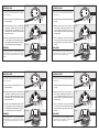
1. Halten Sie zunächst den Einbauring (A) mit einer
Hand in die Öffnung.
2. Mit der andern Hand stecken Sie nacheinander die
3 Spannfedern „Soft-Mount-Clips“ (B) in die dafür
vorgesehenen Schlitze des Einbauringes. Das geht
am einfachsten wenn Sie diese zwischen Daumen
und Zeigefinger nehmen.
3. Nachdem Sie den Lautsprecherteil entsprechend an-
geschlossen haben stecken Sie den Lautsprecher (C)
in den Einbauring und fixieren Ihn durch leichtes dre-
hen im Uhrzeigersinn an den Fixierungspunken .
DEMONTAGE
Zur Demontage gehen Sie wie oben Beschrieben in umge-
kehrter Reihenfolge vor. Die Spannfedern können Sie leicht
mit einem kleinen Schraubenzieher wieder lösen und ent-
nehmen.
1. Schritt
2. Schritt
3. Schritt
A
B
B
B
C
MONTAGE SRC-SERIE
Der zur Montage notwendige Lochausschnitt soll einen Ø
von 195 mm ± 3mm haben. Die Einbautiefe sollte mindes-
tens 75 mm betragen.
1. Halten Sie zunächst den Einbauring (A) mit einer
Hand in die Öffnung.
2. Mit der andern Hand stecken Sie nacheinander die
3 Spannfedern „Soft-Mount-Clips“ (B) in die dafür
vorgesehenen Schlitze des Einbauringes. Das geht
am einfachsten wenn Sie diese zwischen Daumen
und Zeigefinger nehmen.
3. Nachdem Sie den Lautsprecherteil entsprechend an-
geschlossen haben stecken Sie den Lautsprecher (C)
in den Einbauring und fixieren Ihn durch leichtes dre-
hen im Uhrzeigersinn an den Fixierungspunken .
DEMONTAGE
Zur Demontage gehen Sie wie oben Beschrieben in umge-
kehrter Reihenfolge vor. Die Spannfedern können Sie leicht
mit einem kleinen Schraubenzieher wieder lösen und ent-
nehmen.
1. Schritt
2. Schritt
3. Schritt
A
B
B
B
C
ASSEMBLY SRC-SERIE
The hole cutout necessary for the installation should have a
Ø of 195 mm ± 3mm. The installation depth should amount
to at least 75 mm.
1. Hold first the installation ring (A) with a hand into the
opening.
2. With the other hand you put successively the 3
tension springs „Soft-Mount-Clips“ (B) into the slots
of the installation ring planned for it. That can be
done most simply, if you take these between thumbs
and index fingers.
3. After you attached the speaker part accordingly
put the speaker (C) into the installation ring and fix
the bayonet fixing by easy rotation in the clockwise
direction.
DISASSEMBLY
To the disassembly you go like described above in reverse
order forwards. The tension springs can solve and take you
easily with a small slotted screwdriver again.
1. Step
2. Step
3. Step
A
B
B
B
C
-
 1
1

Ask a question and I''ll find the answer in the document
Finding information in a document is now easier with AI
in other languages
- Deutsch: RCS SRC-SERIE Bedienungsanleitung
Related papers
Other documents
-
MB QUART PKC 116 User manual
-
-
 Rockford Fosgate punch RFP-1404D Installation & Operation Manual
-
 Rockford Fosgate HPC1369 User manual
-
 Rockford Fosgate FRC2369 User manual
-
AMAZONAS Carry Sling Operating instructions
-
Kicker 2019 KS Tweeter Owner's manual
-
-
-
Xavax LED Built-in Spotlight User manual


