Page 1 of 5
AMPLIFIED HIGH SPEED PHOTODETECTOR USER’S GUIDE
Thank you for purchasing your Amplified High Speed Photodetector. This user’s guide will help answer any
questions you may have regarding the safe use and optimal operation of your Photodetector.
TABLE OF CONTENTS
I. Amplified High Speed Photodetector Overview ............................................................................................. 1
II. Operation of your Amplified High Speed Photodetector
................................................................................ 1
III. Troubleshooting ............................................................................................................................................... 2
IV. Drawings: Amplified High Speed Photodetectors ........................................................................................... 3
V. Specifications: Amplified High Speed Photodetectors ................................................................................... 3
VI. Schematics: Amplified Photodetectors ............................................................................................................ 4
VII. Glossary of Terms .......................................................................................................................................... 4
I. Amplified High Speed Photodetector Overview
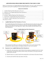
The Amplified Photodetectors contain PIN photodiodes that utilize the photovoltaic effect to convert
optical power into an electrical current and a fixed gain transimpedance amplifier allowing measurement
of <1mW input powers. Figure 1 below identifies the main elements of your Amplified High Speed
Photodetector.
Figure 1: Amplified High Speed Photodetector
When terminated into 50Ω into an oscilloscope, the pulsewidth of a laser can
be measured. When
terminated into a spectrum analyzer, the frequency response of a laser can be measured.
II. Operation of your Amplified High Speed Photodetector
A. Caution: Eye safety precautions must be followed when utilizing any equipment used in the vicinity
of laser beams. Laser beams may reflect from the surface of the detector or the optical mount and
caution must be exercised.
B. Mount the detector to an optical stand by the mounting holes on the bottom of the detector housing.
Sensor
Aperture
SMA
Connector
2.5mm
Power Jack
Power
Switch
DC Monitor
Output
(SMA)

Page 2 of 5
C. Adjust the voltage of the oscilloscope to 20mV/division before connecting the detector.
D. Connect the detector to the oscilloscope using a coaxial cable designed for 10GHz operation. The
DC Monitor cable can be a general purpose cable.
E. Use the 50Ω termination input of the oscilloscope.
F. Connect the DC Monitor to a high impedance device such as a multimeter. Set the device to
millivolts or volts. The output of the DC Monitor converts the average photodiode current to a
voltage output of 1mV/uA. The DC Monitor output has an offset voltage of less than 2mV.
G. Note that the external power supply is a 5VDC regulated supply with a positive center pin. Using an
unregulated power supply or any supply other than 5VDC could damage the detector.
H. After being certain that the damage threshold of the detector is not exceeded, place the detector in
the center of the laser beam.
I. Align the detector for the desired output using either the signal output or the DC Monitor (Note: the
signal output is AC coupled). If a CW laser is used for beam alignment, the DC Monitor output
should be used.
III. Troubleshooting
A. No signal is seen the first time the detector is used.
1. Is the power switch on? Is the external power supply connected?
2. Is your signal a CW signal? If so, there will not be a signal output present because the detector is
AC coupled. There would be an output from the DC Monitor.
3. Be certain that the signal is not high off scale on the oscilloscope.
4. Is the wavelength of the laser within the spectral range of the detector?
5. Has a 50Ω termination input been used?
6
. Try moving the detector within the laser beam.
7. Is there enough light incident on the detector to generate a signal? The detector’s small active
area makes alignment somewhat difficult.
B. A signal has been previously obtained, but not currently.
1. Try steps listed under A.
2. Inspect the active area of the photodiode for any signs of damage.
3. Recheck if the voltage is preset at the external power supply plug.
C. Increasing the power incident on the detector does not result in a higher voltage signal no the
oscilloscope.

Page 3 of 5
1. The detector is probably saturated. You should lower the power incident on the detector to a
lev
el below the saturation point.
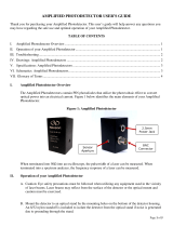
IV. Drawings: Amplified High Speed Photodetectors
A. 818-BB-35A, 818-BB-45A, 818-BB-51A Dimensions:
V. Specifications: Amplified High Speed Photodetectors
Part No. (Model)
818
-BB-35A 818-BB-45A 818-BB-51A
Detector Material
InGaAs GaAs
InGaAs
Rise Time/Fall Time (ps)
<35/<35
<35/<35 <28/<28
Conversion Gain (V/W)
2250 V/W at 1310nm
530 at 830nm 1300 at 2000nm
Power Supply (VDC)
5 5
3
Spectral Range (nm)
830-1650 500-890 830-2150
Bandwidth
20kHz-9GHz 20kHz-9GHz 20kHz-9GHz
Active Area Diameter
32µm 60µm 40µm
Acceptance Angle (1/2 angle)
15
⁰
15
⁰
20
⁰
Noise Equivalent Power (pW/√Hz )
<25 <45 <17
Maximum Linear Rating (mVp-p)
450 450 450
Mounting (Tapped Holes)
8-32 or M4 8-32 or M4 8-32 or M4
Output Connector
SMA SMA SMA

Page 4 of 5
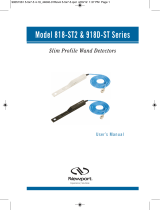
VI. Schematics: Amplified Photodetectors
VII. Glossary of Terms
Amplifier: Provides a power gain of 26dB throughout the photodiode’s bandwidth. The photodiode
current is converted to an output voltage.
Bandwidth: Unlike non-amplified photodetector bandwidth, which is defined as the range of
frequencies from 0Hz (DC) to the frequency at which the amplitude decreases by 3dB, the amplified
photodetectors have a low frequency cutoff of -3dB, which is greater than 0Hz due to the DC Block
Capacitor. Bandwidth and rise time can be approximately related by the equation:
Bandwidth ≈ 0.35/rise time for a Gaussian pulse input.
Bias Voltage: The photodiode’s junction capacitance can be modified by applying a reverse voltage.
The bias voltage reduces the junction capacitance, which causes the photodiode to have a faster
response.
Conversion Gain: The relative level of the optical input power that is amplified and converted into a
voltage output.
Dark Current: When a termination is present, a dark current (nA range) will flow if the photodiode is
biased. Disconnecting the coaxial cable will prevent this current from flowing.
DC Block Capacitor: Prevents the DC voltage that is supplied through the amplifier output from
exiting the detector which would cause a large DC offset voltage. Therefore, the amplified detector is an
AC coupled device and will have a low cut-off frequency as well as a high cut-off frequency.
Decoupling Capacitor: Maintains bias voltage when fast pulses cause the battery voltage to reduce (this
would slow the response time of the photodiode); the capacitor allows the battery to recover to its initial
voltage. It also acts as a filter for external power supplies.
Noise Equivalent Power (NEP): A function of responsivity and dark current and is the minimum
optical power needed for an output signal to noise ratio of 1. Dark current is the current that flows
through a reverse biased photodiode even when light is not present, and is typically on the order of nA.
Shot noise (Ishot) is a source of noise generated in part by dark current; in the case of reversed biased
diodes it is the dominant contributor.
SMA
Connector

Page 5 of 5
Photodiode: Converts photons into a photocurrent.
Resistor: Protects the photodiode from excessive current. This could occur if an external power supply
was too high in voltage, or if its polarity were reversed; this happens when a customer uses their own
power supply.
Responsivity: In amps per watt (A/W), responsivity is the current output of the photodiode for a given
input power, and is determined by the diode structure. Responsivity varies with wavelength and diode
material.
Rise Time/Fall Time: Rise Time is the time taken by a signal to change from a specified low value to a
specified high value. Fall Time is the time taken for the amplitude of a pulse to decrease from a
specified value to another specified value. A larger junction capacitance will slow the detector’s
response time.
SMA Connector: Used to connect the customer’s coaxial cable for high frequencies.
/