Page is loading ...

Page 1 of 5
TTL-ANALOG PHOTODETECTOR USER’S GUIDE
Thank you for purchasing your TTL-Analog Photodetector. This user’s guide will help answer any questions
you may have regarding the safe use and optimal operation of your Photodetector.
TABLE OF CONTENTS
I.
TTL-Analog Photodetector Overview ............................................................................................................. 1
II.
Operation of your TTL-Analog Photodetector ................................................................................................ 1
III.
Timing and Sensitivity Considerations ........................................................................................................... 2
IV.
Troubleshooting ............................................................................................................................................... 2
V.
Drawings: TTL-Analog Photodetectors .......................................................................................................... 3
VI.
Specifications: TTL-Analog Photodetectors ................................................................................................... 3
VII.
Schematics: TTL-Analog Photodetectors ....................................................................................................... 4
VIII.Glossary of Terms ........................................................................................................................................... 4
I. TTL-Analog Photodetector Overview
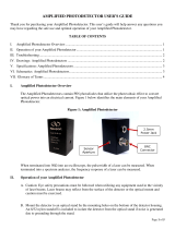
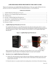
The Photodetectors with TTL Output are based off our standard detectors with the added feature of a
two-state output with an adjustable threshold. Thus, the Analog Output exhibits performance
characteristics on par with our standard products that share the same core part number. Figure 1 below
identifies the main elements of your TTL Photodetector.
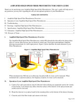
Figure 1: TTL Photodetector
II. Operation of your TTL-Analog Photodetector
A. Caution: Eye safety precautions must be followed when utilizing any equipment used in the vicinity
of laser beams. Laser beams may reflect from the surface of the detector or the optical mount and
caution must be exercised.
B. Mount the detector to an optical stand by the mounting holes on the bottom of the detector housing.
Both English and Metric threads are provided. The holes can be reversed if desired by reinstalling
the baseplate, reversed.
C. Terminate the detector’s Analog Output into 50Ω. Use 50Ω coaxial cable as required on the Analog
Sensor
Aperture
Power
Jack
BNC
Connector
(Analog
Output)
BNC
Connector
(TTL
Output)
Pulse
Stretch
Switch
Threshold
Test Point

Page 2 of 5
and TTL Outputs. The specified performance will only be realized if the cable is less than 1 meter and
the termination impedance on the TTL Output is ≤ 500Ω.
D. Connect the 12V power supply provided.
E. After being certain that the damage threshold of the detector is not exceeded, aim the laser on the
center of the photodiode lens. If an oscilloscope is connected to the Analog Output, align the beam
until the voltage is maximized.
F. The threshold adjust screw varies the Analog Output voltage at which the TTL Output will change
logic states. Its level can be observed by connecting a voltmeter (with input impedance > 100kΩ to
the threshold test point). Performance is optimal when the threshold is adjusted to half the peak
Analog Output however the useful range extends from about 40mV to the analog peak. If the
threshold is adjusted much below 40mV, the TTL Output may oscillate.
G. The duration of the TTL Output can be stretched by moving the toggle switch to the down position.
This is useful when connecting to instruments too slow to recognize pulses only tens of nanoseconds
in duration.
III. Timing and Sensitivity Considerations
A. Timing Considerations: The propagation delay, rise time, fall time, and over/undershoot of the TTL
Output are all proportional to both the length of the coaxial cable and the termination impedance.
The rise time and fall time specifications include the propagation delay and can be improved upon
by shortening the length of the coaxial cable and/or reducing the termination impedance, although
the latter will reduce the logic high voltage. Do not use termination impedances less than 50Ω.
B. Sensitivity Considerations: Since the internal photodiode is essentially a current source, the Analog
Output voltage can be increased by increasing its termination impedance at the expense of slowing
its response time. However, if one’s goal is to increase the sensitivity at the TTL Output, a slowing
of the Analog Output by an order of magnitude will not significantly delay the TTL Output since its
response is considerably slower, yet will increase its sensitivity.
IV. Troubleshooting
A. No signal is seen the first time the detector is used.
1. Be certain that the signal is not high off scale on the oscilloscope.
2. Is the wavelength of the laser within the spectral range of the detector?
3. Has the proper termination impedance been used?
4. Try moving the detector within the laser beam.
5. Is there enough light (see sensitivity spec on the data sheet) incident on the detector to generate a
signal?
B. A signal has been previously obtained, but not currently.
1. Try steps listed under A.

Page 3 of 5
2. Inspect the active area of the photodiode for any signs of damage.
3. Test the power supply for 12VDC output
C. Increasing the power incident on the detector does not result in a higher voltage signal on the
oscilloscope:
1. The detector is probably saturated. You should lower the power incident on the detector to a
level below the saturation point.
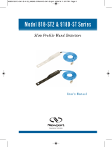
V. Drawings: TTL-Analog Photodetectors
A. 818-BB-21TTL, 818-BB-30TTL Dimensions:
VI. Specifications: TTL-Analog Photodetectors
Part No. (Model)
818-BB-21TTL
818-BB-30TTL
Detector Material
Silicon
InGaAs
Power Supply (VDC)
12
12
Spectral Range (nm)
350-1100 800-1750
Active Area (diameter)
400µm
100µm
Dark Current (nA)
<0.1
<2.0
Acceptance Angle (1/2 angle)
10
⁰
20
⁰
Noise Equivalent Power (pW/√Hz)
<0.01
<0.03
Mounting (Tapped Holes)
8-32 and M4
8-32 and M4
Analog Output
Rise Time/Fall Time (ps)
<300/<300
<175/<175
Responsivity
0.47 A/W at 830nm
0.9A/W at 1300nm
Bandwidth
DC-1.2GHz
DC-1.2GHz
Maximum Linear Rating
CW and Pulse current: 3mA
CW current: 5mA
CW power: 20mW
Termination
50Ω external
50Ωexternal
Output Connector
BNC
BNC
TTL Output
Rise Time/Fall Time (ns)
<8/<9
<8/<9
Bandwidth
DC-60MHz
DC 60-MHz
Termination (Ω)
500
500
Adjustable Trigger Threshold (mV)
40-500
40-500
Minimum Detection Pulsewidth (ns)
8
8
Logic High/Logic Low (V)
>3.0/<0.5
>3.0/<0.5
Pulse Stretch (when enabled)
100ns typical
100ns typical
Output Connector
BNC
BNC

Page 4 of 5
VII. Schematics: TTL-Analog Photodetectors
VIII. Glossary of Terms
Analog Output: Exhibits performance characteristics equal to Newport’s standard photodetectors.
Bandwidth: The range of frequencies from 0Hz (DC) to the frequency at which the amplitude decreases
by 3dB. Bandwidth and rise time can be approximately related by the equation:
Bandwidth ≈ 0.35/rise time for a Gaussian pulse input.
Bias Voltage: The photodiode’s junction capacitance can be modified by applying a reverse voltage.
The bias voltage reduces the junction capacitance, which causes the photodiode to have a faster
response.
BNC Connector: Used to connect the customer’s coaxial cable.

Page 5 of 5
Comparator: Converts the Gaussian pulse from the photodiode to a TTL-compatible logic pulse.
Dark Current: When a termination is present, a dark current (nA range) will flow if the photodiode is
biased. Disconnecting the coaxial cable will prevent this current from flowing.
Decoupling Capacitor: Maintains bias voltage when fast pulses cause the battery voltage to reduce (this
would slow the response time of the photodiode); the capacitor allows the battery to recover to its initial
voltage. It also acts as a filter for external power supplies.
Noise Equivalent Power (NEP): A function of responsivity and dark current and is the minimum
optical power needed for an output signal to noise ratio of 1. Dark current is the current that flows
through a reverse biased photodiode even when light is not present, and is typically on the order of nA.
Shot noise (Ishot) is a source of noise generated in part by dark current; in the case of reversed biased
diodes it is the dominant contributor. NEP is calculated from shot noise and responsivity. For example,
for a responsivity @ 830nm = 0.5 A/W:
q = charge on an electron
Photodiode: Converts photons into a photocurrent.
Pulse Stretch: The function which lengthens the duration of the TTL pulse to approximately 100ns. The
circuit is in pulse stretch mode when the Pulse Stretch switch is not grounded.
Resistor: Protects the photodiode from excessive current. This could occur if an external power supply
was too high in voltage, or if its polarity were reversed; this happens when a customer uses their own
power supply.
Responsivity: In amps per watt (A/W), responsivity is the current output of the photodiode for a given
input power, and is determined by the diode structure. Responsivity varies with wavelength and diode
material.
Rise Time/Fall Time: Rise Time is the time taken by a signal to change from a specified low value to a
specified high value. Fall Time is the time taken for the amplitude of a pulse to decrease from a
specified value to another specified value. A larger junction capacitance will slow the detector’s
response time.
Termination Resistor (50Ω): Reduces signal reflections and balances the 50Ω microstrip/coaxial cable
lines. As a result, half the photodiode current is lost to the internal resistor.
Threshold Adjust: Varies the point on the Gaussian pulse at which the TTL Output changes logic
states.
TTL Output: Can produce pulses less than 10ns.
Hz0.08pA/s0.08pA)1020)(2(1.6x10=2_
9-19
===
−
AxAsqINoiseShot
d
Hz0.16pW/
0.5A
W
*
08.0
/R
830nm
===
Hz
pA
INEP
shot
/