Wacker Neuson DT10 User manual
- Type
- User manual

Operator’s manual
Track dumper
Vehicle model DT10
Edition 1.5
Language en
Article number 1000312270

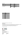
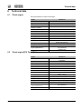
Documentation
Title Language Order no.
Operator’s manual en 1000312270
Spare parts list
de/en/fr 1000312292
de/it/es 1000312295
Issue Issued
1.0 09 / 2013
1.1 09 / 2014
1.2 10 / 2015
1.3 07 / 2016
1.4 05 / 2017
1.5 11 / 2017
Copyright - 2017 Wacker Neuson Linz GmbH, Hörsching
Printed in Austria
All rights reserved
This document may be used by the receiver only for the designated purpose. It may in no way be duplicated or translated
into any other language, in whole or in part, without prior permission in writing from the manufacturer.
The vehicle shown on the title page can be equipped with optional fittings (options).
Original Operator’s Manual
Wacker Neuson Linz GmbH
Flughafenstr. 7
A-4063 Hörsching
Phone (+43) 7221 63000 - 0
Email: [email protected]
www.wackerneuson.com
Document: BA DT10 en
Order no.: 1000312270
Edition: 1.5

BA DT10 en - Edition 1.5 * BaDT10en1_5IVZ.fm I-1
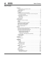
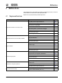
Table of Contents
Table of Contents
I
Introduction
Important information on this Operator’s Manual ..................................................... 1-1
Abbreviations/symbols ....................................................................................... 1-1
Machine overview .................................................................................................... 1-2
Brief description ....................................................................................................... 1-5
Regulations .............................................................................................................. 1-5
Requirements to be met by the operator ........................................................... 1-5
EC Declaration of Conformity for vehicles with a CE mark on the type label .......... 1-6
EC Compliance Statement ................................................................................ 1-6
Type labels and component numbers ...................................................................... 1-7
Serial number .................................................................................................... 1-7
Engine number .................................................................................................. 1-7
Signs and symbols ................................................................................................... 1-8
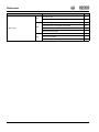
Safety instructions
Identification of warnings and dangers .................................................................... 2-1
Warranty .................................................................................................................. 2-1
Disposal ................................................................................................................... 2-1
Designated use and exemption from liability ........................................................... 2-2
General conduct and safety instructions .................................................................. 2-3
Safety instructions regarding operation ................................................................... 2-5
Safety instructions for maintenance ......................................................................... 2-7
Warning of special hazards ..................................................................................... 2-9
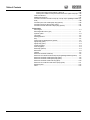
Operation
Overview of the operator's cab (front tip skip model, front tip skip for lightweight material) . 3-1
Control stand overview (high-tip skip model) ........................................................... 3-2
Control stand overview (model with front tip skip) ................................................... 3-3
Control stand overview (swivel tip skip model) ........................................................ 3-4
8 Alternator charge function indicator light ........................................................ 3-5
9 Engine oil pressure indicator light ................................................................... 3-5
10 Water temperature indicator light ................................................................. 3-5
11 Indicator light – diesel engine glow plug preheating ..................................... 3-5
Putting into operation ............................................................................................... 3-6
Safety instructions ........................................................................................... 3-12
Machine operation ................................................................................................. 3-25
Malfunctions
Engine malfunctions ................................................................................................ 4-1
Maintenance
Introduction .............................................................................................................. 5-1
Fuel system ............................................................................................................. 5-7
General .............................................................................................................. 5-9
Refueling from barrels ....................................................................................... 5-9
Engine lubrication system ...................................................................................... 5-12
Checking the oil level ....................................................................................... 5-12
Air filter ................................................................................................................... 5-15
Hydraulic system ................................................................................................... 5-17
Checking the coolant level ............................................................................... 5-23
Adding coolant ................................................................................................. 5-23
Tracks .................................................................................................................... 5-28
Electrical system .................................................................................................... 5-30
General maintenance ............................................................................................ 5-33
Cleaning with washing solvents ....................................................................... 5-33
Cleaning with compressed air ......................................................................... 5-33
Table of Contents

I-2 BA DT10 en - Edition 1.5 * BaDT10en1_5IVZ.fm
Table of Contents
Cleaning with a high-pressure cleaner or steam jet ......................................... 5-33
Cleaning with volatile and easily flammable anticorrosion agents and sprays: 5-33
Fluids and lubricants .............................................................................................. 5-35
Maintenance plan DT10 ......................................................................................... 5-37
Lubrication schedule DT10 with front tip skip, front tip skip for lightweight material (op-
tional) ..................................................................................................................... 5-39
Lubrication plan of DT10 with high tip skip (optional) ............................................ 5-40
Lubrication plan DT10 with front skip (option) ........................................................ 5-41
Lubrication schedule DT10 with rotary tip skip (optional) ...................................... 5-42
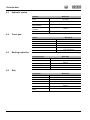
Technical data
Diesel engine ........................................................................................................... 6-1
Diesel engine EPA Tier 4 (Opt.) ............................................................................... 6-1
Hydraulic system ...................................................................................................... 6-2
Travel gear ............................................................................................................... 6-2
Working hydraulics ................................................................................................... 6-2
Skip .......................................................................................................................... 6-2
Front tip skip for lightweight load (optional) ............................................................. 6-3
High-tip skip (option) ................................................................................................ 6-3
High-tip skip (option) ................................................................................................ 6-3
Loader unit (option) .................................................................................................. 6-3
Front skip (option) .................................................................................................... 6-4
Swivel skip (optional) ............................................................................................... 6-4
Noise levels .............................................................................................................. 6-5
Vibration ................................................................................................................... 6-5
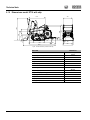
Dimensions model DT10 with skip ........................................................................... 6-6
Dimensions of model DT10 with front tip skip for lightweight material (optional) ..... 6-7
Dimensions model DT10 with high-tip skip (option) ................................................. 6-8
Dimensions model DT10 with high-tip skip (option) ................................................. 6-9
Dimensions model DT10 with front skip (option) ................................................... 6-10
Dimensions for model DT10 with swivel -tip skip (option) ...................................... 6-11
Electrical system .................................................................................................... 6-12
Fuses ..................................................................................................................... 6-12

BA DT10 en - Edition 1.5 * BaDT10en1_5IVZ.fm I-3
Table of Contents

I-4 BA DT10 en - Edition 1.5 * BaDT10en1_5SIX.fm
Index
A
Abbreviations .........................................................................................1-1
Air filter .................................................................................................5-15
Applications with lifting gear ..................................................................2-6
B
Battery master switch ..........................................................................3-20
Biodegradable oil .................................................................................5-25
Bleeding the fuel system ......................................................................5-11
C
Charge function .....................................................................................3-5
Chassis ..................................................................................................6-2
Check lists .............................................................................................3-7
Clean the filter cup ...............................................................................5-10
Clean the fuel filter ...............................................................................5-10
Control stand overview .................................................... 3-1, 3-2, 3-3, 3-4
Crane-lifting bracket .............................................................................3-21
D
Designated use and exemption from liability .........................................2-2
Drain engine oil ....................................................................................5-13
Drain fuel ...............................................................................................5-8
Drain hydraulic oil ................................................................................5-19
Draining coolant ...................................................................................5-24
Driving on public roads ........................................................................3-12
DT08 PL .................................................................................................1-7
E
Emergency lowering of the skip ...........................................................3-29
Engine ....................................................................................................6-1
F
Fluids and lubricants ............................................................................5-35
H
High-tip skip (option) ............................................................................3-18
Hydraulic PTO shaft (HPTO) (option) ..................................................3-30
Hydraulic system ...................................................................................6-2
I
Instrument panel overview ............................................... 3-1, 3-2, 3-3, 3-4
L
Legal regulations ...................................................................................1-5
M
Maintenance
Adding coolant .............................................................................. 5-22
Adding engine oil .......................................................................... 5-13
Adding hydraulic oil ...................................................................... 5-18
Air filter ................................................................................5-16, 5-17
Biodegradable oil .......................................................................... 5-25
Check the hydraulic oil level ......................................................... 5-18
Checking the coolant level ........................................................... 5-22
Checking the engine-oil level ....................................................... 5-12
Cleaning ....................................................................................... 5-33
Diesel engine maintenance plan .................................................. 5-37
Electrical system .......................................................................... 5-30
Engine lubrication system ............................................................ 5-12
Fluids and lubricants .................................................................... 5-35
Fuel system .................................................................................... 5-7
General maintenance ................................................................... 5-33
Hydraulic pressure lines ............................................................... 5-26
Hydraulic system .......................................................................... 5-17
Instructions concerning specific components ............................... 5-31
Lubricating the lift cylinder ............................................................ 5-43
Lubrication plan ............................................................................ 5-39
Maintenance opening ................................................................... 5-43
Oil cooler ...................................................................................... 5-22
Pivots and hinges ......................................................................... 5-34
Servicing and maintenance at regular intervals ........................... 5-30
Threaded fittings ........................................................................... 5-34
Track maintenance ....................................................................... 5-28
Maintenance prop ................................................................................. 5-1
N
Noise levels ........................................................................................... 1-9
Notes
On this Operator’s Manual ............................................................. 1-1
O
Operation .............................................................................................. 3-1
Before starting the engine
3-9
Control stand overview ..............................................3-1, 3-2, 3-3, 3-4
Engine start .................................................................................... 3-9
Parking the machine ..................................................................... 3-19
Starting vehicle travel ................................................................... 3-13
P
Putting into operation
Check lists ...................................................................................... 3-7
Putting into operation for the first time ............................................ 3-6
Safety instructions .......................................................................... 3-6
R
Refueling ............................................................................................... 5-7
Replacing the filter cartridge ............................................................... 5-10
Replacing the oil filter cartridge ........................................................... 5-14
Running-in period .................................................................................. 3-6
Index
I

S
Safety instructions .................................................................................2-1
Applications with lifting gear ...........................................................2-6
General conduct .............................................................................2-3
Identification ....................................................................................2-1
Maintenance ...................................................................................2-7
Operation ........................................................................................2-5
Special hazards ..............................................................................2-9
Trailers and attachments ................................................................2-6
Transportation .................................................................................2-6
Signs and symbols .................................................................................1-8
Starting aid ...........................................................................................3-12
Swivel skip (option) ..............................................................................3-18
T
Technical data
Coolant compound table ...............................................................6-12
Electrical system ...........................................................................6-12
Engine ...........................................................................................6-12
Noise level ....................................................................................6-12
Working hydraulics .......................................................................6-12
Track maintenance ..............................................................................5-28
Travel drive ..........................................................................................5-30
V
Vehicle
Brief description ..............................................................................1-5
Loading and transporting ..............................................................3-22
W
Warranty ................................................................................................2-1
Working hydraulics ................................................................................6-2

I-6 BA DT10 en - Edition 1.5 * BaDT10en1_5SIX.fm
Index

BA DT10 en - Edition 1.5 * dt10b110.fm 1-1
Introduction
1 Introduction
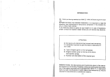
1.1 Important information on this Operator’s Manual
Please store the Operator’s Manual in the storage bin under the engine cover.
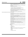
This Operator’s Manual contains important information on how to work safely, correctly
and economically with the machine. Therefore, it aims not only at new operators, but it also
serves as a reference for experienced ones. It helps to avoid hazardous situations and
reduce repair costs and downtimes. Furthermore, the reliability and the service life of the
machine will be increased by following the instructions in the Operator’s Manual. This is
why the operator’s manual must always be kept at hand in the machine.
The safety of the operator and other persons heavily depends on how safely the machine
is used. Therefore, carefully read and understand this Operator’s Manual prior to the first
drive. This Operator’s Manual will help to familiarize yourself more easily with the machine,
thereby enabling you to use it more safely and efficiently.
Prior to the first drive, carefully read chapter “Safety Instructions” as well, in order to be
prepared for possible hazardous situations, as it will be too late for it during operation. As a
rule, keep the following in mind:
Careful and prudent working is the best way to avoid accidents!
Operational safety and readiness of the vehicle do not only depend on your skill, but also
on maintenance and servicing of the vehicle. This is why regular maintenance and servic-
ing is absolutely necessary.
Extensive maintenance and repair work must always be performed by a technician with
appropriate training. Insist on using original spare parts when performing maintenance and
repair work. This ensures operational safety and readiness of your machine, and main-
tains its value.
Your Neuson dealer will be happy to answer any further questions regarding the machine
or the Operator’s Manual.
Abbreviations/symbols
• Identifies a list
• Subdivision within lists or an activity. Follow the steps in the recommended order.
☞Identifies an activity
➥Description of the effects or results of an activity
s. fig. (w/o. fig.) = without figure
"Opt." = Optional
The abbreviation “Opt.” indicates control elements or other groups of the machine that can
be installed as an option.
This symbol shows the travel direction – for better orientation in figures and graphics.

1-2 BA DT10 en - Edition 1.5 * * dt10b110.fm
Introduction
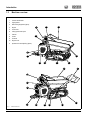
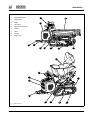
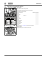
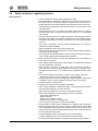
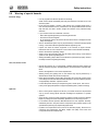
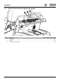
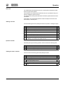
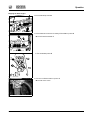
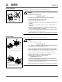
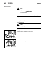
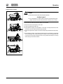
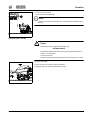
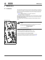
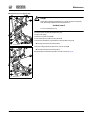
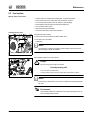
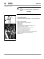
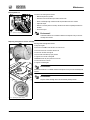
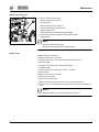
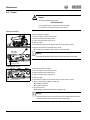
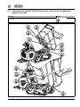
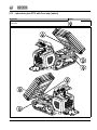
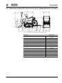
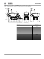
1.2 Machine overview
Fig. 1: Vehicle outside views
1 Control stand/handle
2 Tipping trailer
3 Self-loading equipment (option)
4 Engine
5 Travel drive
6 Lifting eye/tie-down point
7Chassis
8 Tracks
9 Foothold
10 Engine cover
11
Hydraulic PTO shaft (HPTO) (
Option
)
1
2
3
5
6
7
10
8
2
9
7
6
5
4
8
11
11
1
4
6
9
10

BA DT10 en - Edition 1.5 * dt10b110.fm 1-3
Introduction
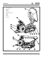
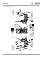
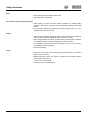
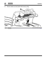
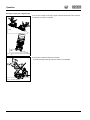
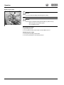
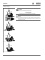
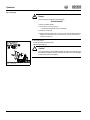
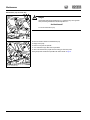
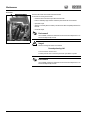
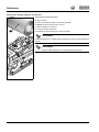
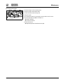
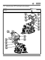
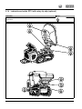
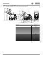
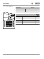
Fig. 2: Vehicle outside views
1 Control stand/handle
2 Tipping trailer
3 Engine
4 Travel drive
5 Lifting eye/tie-down point
6Chassis
7 Tracks
8 Foothold
9 Engine cover
1
2
5
3
8
6
9
4
3
7
1
2
5
5
8
9
4
5
6
7

1-4 BA DT10 en - Edition 1.5 * * dt10b110.fm
Introduction
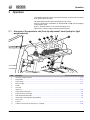
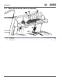
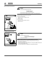
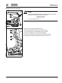
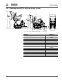
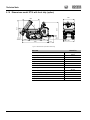
Fig. 3: Vehicle outside views
1 Control stand/handle
2 Tipping trailer
3 Engine
4 Travel drive
5 Lifting eye/tie-down point
6Chassis
7 Tracks
8 Foothold
9 Engine cover
1
2
5
3
8
6
9
4
3
7
1
2
5
5
8
9
4
5
6
7

BA DT10 en - Edition 1.5 * dt10b110.fm 1-5
Introduction
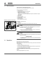
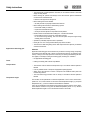
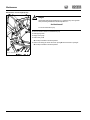
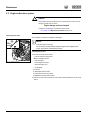
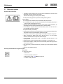
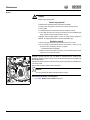
1.3 Brief description
The DT10 dumper is a self-propelled work machine.
Get informed on and follow the legal regulations of your country.
The main components of the vehicle are:
• Tracked travel gear
• Control stand with integrated oil and fuel tanks
• Internal combustion engine
• Model DT10: two-cylinder diesel engine
• Model DT10: two-cylinder diesel engine that corresponds to the EPA tier-4 regula-
tions (optional)
• Tipping trailer
• High-tip skip (option)
• Self-loading equipment (option)
• Front skip (option)
• Swivel skip (option)
• Skip for lightweight load (optional)
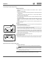
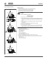
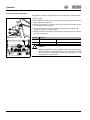
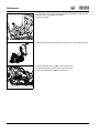
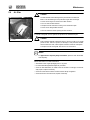
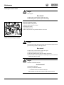
Definition of operator’s control stand
The dumper’s control stand is the:
• Foothold
• Control stand
The vehicle may only be operated from the running board and control stand.
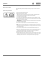
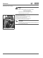
Danger!
The operator must not lean or reach outside the dimensions of the vehicle.
This applies in particular to their feet! Otherwise –
Accident hazard!
☞Stand on the foothold ensuring that neither your feet nor other limbs pro-
trude beyond the dimensions of the vehicle!
Danger!
The operator must always firmly hold onto the handle of the control stand with
both hands! Otherwise –
Accident hazard!
☞The operator is subject to high acceleration forces in particular when start-
ing vehicle travel!
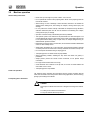
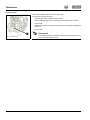
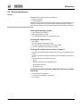
1.4 Regulations
Requirements to be met by the operator
Earth moving machines may be driven and serviced only by persons who meet the follow-
ing requirements:
• 18 years or older
• Physically and mentally suited for this work
• Persons have been instructed in driving and servicing the earth moving machine and
have proven their qualifications to the contractor
• Persons are expected to perform work reliably.
They have been appointed by the contractor for driving and servicing the earth moving
machine.
Observe the legal regulations of your country.
Fig. 4: Control stand

1-6 BA DT10 en - Edition 1.5 * * dt10b110.fm
Introduction
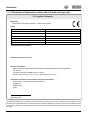
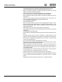
1.5 EC Declaration of Conformity for vehicles with a CE mark on the type label
The indications specified above correspond to the existing information at time of going to press. They have possibly changed in the mean-
time (refer to the original declaration of conformity supplied with the vehicle). Applies to EU countries, and countries with legislation similar
to that of the EU. Applies to all vehicles with CE marks that have not been modified without authorization since the product was placed on
the market.
Manufacturer
Wacker Neuson Linz GmbH, Flughafenstr. 7, 4063 Hörsching, Austria
Product
Conformity assessment procedure
-
Notified body involved in procedure
-
Directives and standards
With this document we declare that this product corresponds to the applicable regulations of the following directives
and standards:
2014/30/EG, 2000/14/EU, 97/68/EU, EN ISO 12100:210;
EN 474-1:2006 (up to 5.5.8.1, 5.8.2, 5.9, 5.19.1), EN 474-6:2010 (up to 5.7.3.3),
Authorized representative for the compilation of technical documentation
Annette Ortmayr, Team Leader Technical Documentation
Flughafenstr. 7
4063 Hörsching
Austria
Machine designation Compact Dumper
Machine model D19-01
Trade name DT10
Serial number xxxxxxxx
Engine / output kW Z482/9.7
Measured sound power level dB(A) 101
Guaranteed sound power level dB(A) 101
Johannes Mahringer,
Managing director
EC Compliance Statement

BA DT10 en - Edition 1.5 * dt10b110.fm 1-7
Introduction
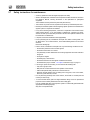
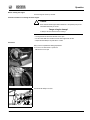
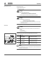
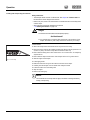
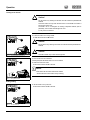
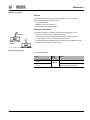
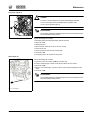
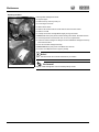
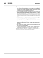
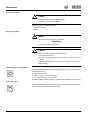
1.6 Type labels and component numbers
Serial number
The number is located on the type label.
The type label is located at the front on the control stand.
Type label information (example):
Machine designation: COMPACT DUMPER
Model: ---------------
Model year: ---------------
CEE no. (EEC no.) ---------------
Output: ---------------
Serial no.: ---------------
Max. payload: ---------------
GWR: ---------------
Operating weight: ---------------
Front GAWR: ---------------
Transport weight: ---------------
Rear GAWR: ---------------
Version: ---------------
Other information – see chapter 6 Technical data on page 6-1
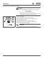
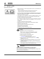
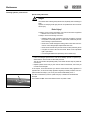
Engine number
The type label (arrow) is located on the valve cover.
COMPACT DUMPER
Fig. 5: Position of the type label
Fig. 6: Engine number

1-8 BA DT10 en - Edition 1.5 * * dt10b110.fm
Introduction
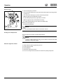
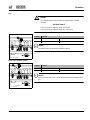
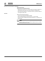
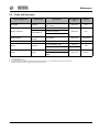
1.7 Signs and symbols
XX
XX

BA DT10 en - Edition 1.5 * dt10b110.fm 1-9
Introduction
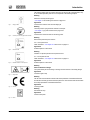
The following states signs and symbols which are not unequivocally comprehensible. They
do not contain explanatory text and are not explained in the following chapters.
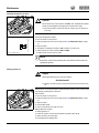
Meaning
Machine is raised by the lifting eyes
– see chapter Crane handling the machine on page 3-21
Application
On the chassis near the front and rear lifting eyes
Meaning
Tie-down points for tying down the machine for transport.
– see chapter Tying down the machine on page 3-23
Application
On the chassis at the front and rear anchoring points
Meaning
Noise levels produced by the machine.
L
Wa
= sound power level
Other information – see chapter 6.13 Noise levels on page 6-5
Application
Protective plate on control stand
Meaning
Indication of operator-perceived sound pressure level.
L
Pa
= sound pressure level
Other information – see chapter 6.13 Noise levels on page 6-5
Application
Protective plate on control stand
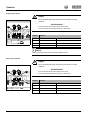
Meaning
General indication of danger
This symbol alerts persons standing or working near the machine of an existing danger.
Application
On left and right of skip
Meaning
The CE mark means that the machine meets the requirements of the Machine Directive
and that the conformity procedure has been performed. The machine meets all the health
and safety requirements of the Machine Directive.
Application
On the type label
Meaning
Add diesel fuel only!
Application
On the control panel
Fig. 7: Lifting eye label
Fig. 8: Label for points used for tying down the machine
Fig. 9: Noise level label
XX
Fig. 10: Label with indication of sound pressure
XX
Fig. 11: Danger label
Fig. 12: CE mark
Fig. 13: Diesel

1-10 BA DT10 en - Edition 1.5 * * dt10b110.fm
Introduction
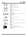
Meaning
The reservoir contains hydraulic oil.
– see chapter Adding hydraulic oil on page 5-18
Application
Next to the filler inlet of the hydraulic oil reservoir
Meaning
Read the Operator’s Manual before using the machine.
Application
On left and right of skip
Meaning
Use a safety prop before performing work under the skip.
Application
On left and right of skip
Meaning
General indication of danger
This symbol alerts persons standing or working near the machine of an existing shearing
hazard around the machine.
Application
On left and right of skip
Meaning
Do not touch hot surfaces, wait for parts to cool down.
Application
Near the exhaust system
Meaning
Danger of burns, and danger due to rotating fan! Stop the engine before opening the
engine cover.
Application
On the engine cover
Meaning
Danger due to components under spring tension! Indicates the device for adjusting track
tension.
Application
Right and left side of chassis
Meaning
This label explains the machine’s control elements
– see chapter 3. 1 Overview of the operator's cab (front tip skip model, front tip skip for
lightweight material) on page 3-1
Application
On the control stand
Fig. 14: Hydraulic oil
Fig. 15: Read and understand the Operator’s Manual
Fig. 16: Safety prop
Fig. 17: Shearing hazard
Fig. 18: Hot surfaces
Fig. 19: Engine stop
Fig. 20: Track tension adjustment
Fig. 21: Main label

BA DT10 en - Edition 1.5 * dt10b110.fm 1-11
Introduction
Meaning
Indication of throttle.
Application
On the control stand
Meaning
The machine’s control stand is not enclosed, therefore always carry an ear protection.
Application
On the control stand
Meaning
Battery master switch – see chapter Battery master switch on page 3-20
Application
Protective plate on control stand
Importance (optional)
The reservoir contains biodegradable hydraulic oil.
– see chapter Dirty hydraulic oil, lack of oil or wrong hydraulic oil – on page 5-17
Application
On the hydraulic oil reservoir
Fig. 22: Accelerator
Fig. 23: Ear protection
Fig. 24: Battery master switch
Fig. 25: Biodegradable hydraulic oil

1-12 BA DT10 en - Edition 1.5 * * dt10b110.fm
Introduction
Page is loading ...
Page is loading ...
Page is loading ...
Page is loading ...
Page is loading ...
Page is loading ...
Page is loading ...
Page is loading ...
Page is loading ...
Page is loading ...
Page is loading ...
Page is loading ...
Page is loading ...
Page is loading ...
Page is loading ...
Page is loading ...
Page is loading ...
Page is loading ...
Page is loading ...
Page is loading ...
Page is loading ...
Page is loading ...
Page is loading ...
Page is loading ...
Page is loading ...
Page is loading ...
Page is loading ...
Page is loading ...
Page is loading ...
Page is loading ...
Page is loading ...
Page is loading ...
Page is loading ...
Page is loading ...
Page is loading ...
Page is loading ...
Page is loading ...
Page is loading ...
Page is loading ...
Page is loading ...
Page is loading ...
Page is loading ...
Page is loading ...
Page is loading ...
Page is loading ...
Page is loading ...
Page is loading ...
Page is loading ...
Page is loading ...
Page is loading ...
Page is loading ...
Page is loading ...
Page is loading ...
Page is loading ...
Page is loading ...
Page is loading ...
Page is loading ...
Page is loading ...
Page is loading ...
Page is loading ...
Page is loading ...
Page is loading ...
Page is loading ...
Page is loading ...
Page is loading ...
Page is loading ...
Page is loading ...
Page is loading ...
Page is loading ...
Page is loading ...
Page is loading ...
Page is loading ...
Page is loading ...
Page is loading ...
Page is loading ...
Page is loading ...
Page is loading ...
Page is loading ...
Page is loading ...
Page is loading ...
Page is loading ...
Page is loading ...
Page is loading ...
Page is loading ...
Page is loading ...
Page is loading ...
Page is loading ...
Page is loading ...
Page is loading ...
Page is loading ...
Page is loading ...
Page is loading ...
Page is loading ...
Page is loading ...
Page is loading ...
Page is loading ...
Page is loading ...
Page is loading ...
Page is loading ...
Page is loading ...
-
 1
1
-
 2
2
-
 3
3
-
 4
4
-
 5
5
-
 6
6
-
 7
7
-
 8
8
-
 9
9
-
 10
10
-
 11
11
-
 12
12
-
 13
13
-
 14
14
-
 15
15
-
 16
16
-
 17
17
-
 18
18
-
 19
19
-
 20
20
-
 21
21
-
 22
22
-
 23
23
-
 24
24
-
 25
25
-
 26
26
-
 27
27
-
 28
28
-
 29
29
-
 30
30
-
 31
31
-
 32
32
-
 33
33
-
 34
34
-
 35
35
-
 36
36
-
 37
37
-
 38
38
-
 39
39
-
 40
40
-
 41
41
-
 42
42
-
 43
43
-
 44
44
-
 45
45
-
 46
46
-
 47
47
-
 48
48
-
 49
49
-
 50
50
-
 51
51
-
 52
52
-
 53
53
-
 54
54
-
 55
55
-
 56
56
-
 57
57
-
 58
58
-
 59
59
-
 60
60
-
 61
61
-
 62
62
-
 63
63
-
 64
64
-
 65
65
-
 66
66
-
 67
67
-
 68
68
-
 69
69
-
 70
70
-
 71
71
-
 72
72
-
 73
73
-
 74
74
-
 75
75
-
 76
76
-
 77
77
-
 78
78
-
 79
79
-
 80
80
-
 81
81
-
 82
82
-
 83
83
-
 84
84
-
 85
85
-
 86
86
-
 87
87
-
 88
88
-
 89
89
-
 90
90
-
 91
91
-
 92
92
-
 93
93
-
 94
94
-
 95
95
-
 96
96
-
 97
97
-
 98
98
-
 99
99
-
 100
100
-
 101
101
-
 102
102
-
 103
103
-
 104
104
-
 105
105
-
 106
106
-
 107
107
-
 108
108
-
 109
109
-
 110
110
-
 111
111
-
 112
112
-
 113
113
-
 114
114
-
 115
115
-
 116
116
-
 117
117
-
 118
118
-
 119
119
-
 120
120


Wacker Neuson DT10 User manual
- Type
- User manual
Ask a question and I''ll find the answer in the document
Finding information in a document is now easier with AI
Related papers
-
Wacker Neuson EZ38 User manual
-
-
-
-
-
-
-
-
-
Other documents
-
 Solé Diesel MINI-23 User manual
-
 Solé Diesel MINI-10 User manual
-
 Solé Diesel Mini-32 User manual
-
 TEIKO COBA1300 User manual
-
 wellbots EVA_01 User manual
-
Sempell Hydaulic Actuators PED O&SI User guide
-
Anova ATB2502 Owner's manual
-
 AUSA D 1000 AP User manual
-
 ROBEL 13.45SKS Vers. 01 Operating instructions
-
Samsung MM-DT10 User manual


