
Page 1 of 40
LINAK.COM/DESKLINE
DL12, DL14, DB14 and DL17 system
with CBD6S
User manual

Page 2 of 40
Contents
Preface ............................................................................................................................................ 3
Valid for ............................................................................................................................................ 4
Important information ................................................................................................................... 5
Safety instructions .......................................................................................................................... 5
General ....................................................................................................................................... 5
Before installation, reinstallation or troubleshooting ..................................................................... 6
Before start-up ............................................................................................................................ 6
During operation .......................................................................................................................... 6
Misc. ........................................................................................................................................... 6
Only for EU markets ....................................................................................................................... 7
Only for Non EU markets .............................................................................................................. 7
Misuse ........................................................................................................................................... 7
Repairs ........................................................................................................................................... 8
Manufacturer’s declaration........................................................................................................... 8
Misc. on the DESKLINE
®
system .....................................................................................................9
Warranty.......................................................................................................................................9
Maintenance.................................................................................................................................9
Service of double-insulated products ............................................................................................ 9
ETL-markering ................................................................................................................................10
Description of the DESKLINE
®
system ........................................................................................11
Mounting guidelines for the DL14 system ................................................................................. 12
Mounting top ........................................................................................................................... 12
Mounting foot .......................................................................................................................... 14
Mounting guidelines for the DL12 system ................................................................................ 15
Mounting top ........................................................................................................................... 15
Mounting foot .......................................................................................................................... 15
Mounting the desk ..................................................................................................................... 15
Mounting guidelines for the DL17 system ................................................................................ 16
Mounting top ........................................................................................................................... 16
Mounting foot .......................................................................................................................... 16
Mounting guidelines for the DB14 ............................................................................................ 18
Mounting guidelines for the CBD6S (SMPS) ............................................................................. 20
Electric connection of the DB/DL system .................................................................................. 21
Initialisation of the DESKLINE parallel system ......................................................................... 22
PIEZO
TM
description (optional) ................................................................................................... 23
Accessories ................................................................................................................................... 24
Disposal of LINAK products ......................................................................................................... 25
Labels .......................................................................................................................................... 26
Drawing appendix ......................................................................................................................... 27
Declaration of conformity ............................................................................................................ 36
Addresses ....................................................................................................................................... 40

Page 3 of 40
Preface
Dear User,
We are delighted that you have chosen a product from LINAK
®
.
LINAK systems are high-tech products based on many years of experience in the manufacture and development
of actuators, electric control boxes, controls and chargers.
This User Manual does not address the end-user. It is intended as a source of information for the manufacturer
of the equipment or system only, and it will tell you how to install, use and maintain your LINAK electronics.
It is the responsibility of the manufacturer of the end-user product to provide a User Manual where relevant
safety information from this manual is passed on to the end-user.
We are sure that your LINAK product/system will give you many years of problem-free operation.
Before our products leave the factory, they undergo full function and quality testing. Should you nevertheless
experience problems with your LINAK product/system, you are always welcome to contact your local contact.
LINAK subsidiaries and some distributors situated all over the world have authorised service centres, which are
always ready to help you.
LINAK provides a limited warranty on its products. This warranty is, however, subject to correct use in
accordance with the specifications, maintenance being done correctly, and any repairs being carried out at a
service centre, which is authorised to repair LINAK products. Changes in installation and use of LINAK products/
systems can affect their operation and durability. The products are not to be opened by unauthorised personnel.
You can review the full terms of the LINAK warranty on the LINAK website www.linak.com/warranty.
The User Manual has been written based on our present technical knowledge. We are constantly working on
updating the information and we therefore reserve the right to carry out technical modifications.
LINAK A/S

Page 4 of 40
Valid for:
This User Manual is valid for the following products:
(See the first 3 - 5 characters on the label)
Columns: DL12, DL14, DL17
Built-in actuators: DB14
Control boxes: CBD6S 200W, CBD6S 300W
Controls: DP1U/DPF1M (if memory function is required)
DP1C/DPT/DPF1C (if memory function and display is required)
or DPA/DPB/DPH/DP1K/DP1V/DPF1K/DPG1K (if only up/down is required)
or DPF1D (if display is required),
or DPG1M/DPG1B (if reminder, Bluetooth
®
and memory is required)
or DPG1C (“If reminder, Bluetooth
®
, memory and display is required)

Page 5 of 40
Safety instructions
General
Important information
Important information on LINAK
®
products can be found under the following
headings:
Warning!
Failure to comply with these instructions may result in accidents involving
serious personal injury.
Failing to follow these instructions can result in the product being damaged
or being destroyed.
Safe use of the system is possible only when the operating instructions are read
completely and the instructions contained are strictly observed.
Failure to comply with instructions marked with the ”NOTE” symbol may result in
serious damage to the system or one of its components.
It is important for everyone who is to connect, install, or use the systems to
have the necessary information and access to this User Manual. Follow the
instructions for mounting – there is a risk of injury if these instructions are not
followed.
The appliance is not intended for use by young children or infirm persons
without supervision.
If there is visible damage to the product, do not install it.
Please note that during construction of applications in which the actuator
is to be fitted, there must be no possibility of personal injury, for example
squeezing of fingers or arms.
Assure free space for movement of the application in both directions to avoid
blockades.

Page 6 of 40
Before installation, reinstallation, or troubleshooting
• Stop the DB/DL
• Pull out the mains plug.
• Relieve the DB/DL of any loads, which may be released during the work.
Before start-up:
• Make sure that the system has been installed as instructed in this User Manual.
• Make sure that the voltage of the control box is correct before connecting the
system to the mains.
• System connection. The individual parts must be connected before connecting the
control box to the mains. See the User Manual for LINAK actuators, if necessary.
During operation:
• If the control box makes unusual noises or smells, switch off the mains voltage
immediately.
• Take care that the cables are not damaged.
• Unplug the mains cable on mobile equipment before moving it.
• The products must only be used in an environment, that corresponds to their IP
protection.
Misc.
The actuator system has a sound level below 55 dB(A) in typical applications.
Updated manuals and declarations can always be found here:
www.linak.com/deskline

Page 7 of 40
Only for EU markets
This appliance can be used by children aged from aged 8 years and above
and persons with reduced physical, sensory or mental capabilities or lack of
experience and knowledge if they have been given supervision or instruction
concerning use of the appliance in a safe way and understand the hazards
involved.
Children shall not play with the appliance. Cleaning and user maintenance
shall not be made by children without supervision.
Only for Non EU markets
Persons who do not have the necessary experience or knowledge of the
product/products must not use the product/products. Besides, persons with
reduced physical, sensory or mental abilities must not use the product/
products, unless they are under surveillance or they have been thoroughly
instructed in the use of the apparatus by a person who is responsible for the
safety of these persons.
Moreover, children must be under surveillance to ensure that they do not
play with the product.
It is the operator’s responsibility to ensure that there is free space for the
application to move without risk for the operator or bystanders before
operating the application.
Misuse
Do not overload the actuators – this can cause danger of personal injury and
damage to the system.
Do not use the actuator system for lifting persons. Do not sit or stand on a
table while operating – risk of personal injury.
Do not use the system in environments other than the intended indoor use

Page 8 of 40
Repairs
In order to avoid the risk of malfunction, all repairs must only be carried out by authorised LINAK service centres or repairers,
as special tools must be used and special gaskets must be fitted. Products under warranty must also be returned to authorised
LINAK service centres.
Further information on the LINAK warranty can be found on the LINAK website www.linak.com/warranty.
Warning!
If any of the DESKLINE
®
products are opened, there will be a risk of subsequent malfunction.
Warning!
The DESKLINE
®
systems do not withstand cutting oil.
DECLARATION OF INCORPORATION OF PARTLY COMPLETED MACHINERY
LINAK A/S
Smedevænget 8
DK - 6430 Nordborg
Herewith declares that LINAK DESKLINE
®
products as characterized by the following models and types:
Control Boxes CBD6S
Linear Actuators DB5, DB6, DB7, DB9, DB12, DB14, DB16, LA23, LA31
Lifting Columns DL1A, DL2, DL4S, DL5, DL6, DL7, DL8, DL9, DL10, DL11, DL12, DL14, DL15,
DL16, DL17, DL19, BASE1
Desk Panels DPA, DPB, DPH, DPF, DPG1K, DPG1M, DPG1B, DPG1C, DPT, DP1, DP1CS,
DP1K, DP1V, DP1U
RF Controls HB10RF, HB20RF, RFT, RFRL
Accessories BA001, SLS, Kick & Click
comply with the following parts of the Machinery Directive 2006/42/EC, ANNEX I, Essential health and
safety requirements relating to the design and construction of machinery:
1.5.1 Electricity supply
The relevant technical documentation is compiled in accordance with part B of Annex VII and that this
documentation or part hereof will be transmitted by post or electronically to a reasoned request by the
national authorities.
This partly completed machinery must not be put into service until the final machinery into
which it is to be incorporated has been declared in conformity with the provisions of the
Machinery Directive 2006/42/EC where appropriate.
Nordborg, 2017-12-08
LINAK A/S
John Kling, B.Sc.E.E.
Certification and Regulatory Affairs
Authorized to compile the relevant technical documentation
Original Declaration

Page 9 of 40
Misc. on the DESKLINE
®
system
This system is a DESKLINE system developed for desks and for indoor use in offices. Do not use it in industrial kitchens or in
other enviroments that have to be cleaned with aggressive detergents.
Do not bolt the legs to the floor so that free movement is prevented. This could cause serious damage to the legs in fault
situations.
Warranty
This DESKLINE product is subject to warranty pursuant to the terms of LINAK DESKLINE Warranty Paper, available on the LINAK
website www.linak.com/warranty.
Maintenance
Clean dust and dirt on the outside of the system at appropriate intervals and inspect them for damage and breaks.
Inspect the connections, cables and plugs and check for correct functioning as well as fixing points.
Service of double insulated products:
Class II
A Class II or double insulated electrical appliance is one which has been designed in such a way that it does not require a
safety electric earth connection (US: ground).
The basic requirement is that no single failure can result in dangerous voltage becoming exposed so that it might cause an
electric shock and that this is achieved without relying on an earthed metal casing. This is usually achieved at least in part by
having two layers of insulating material surrounding live parts or by using reinforced insulation.
There is no earthing/grounding means provided on the product, and no earthing/grounding means is to be added to the
product.
In Europe, a double insulated appliance must be labelled “Class II”, “double insulated” or bear the double insulation symbol
(a square inside another square).
Servicing a double-insulated product requires extreme care and knowledge of the system, and is to be done only by qualified
service personnel. Replacement parts for a double-insulated product must be identical to the parts they replace.
Cleaners and disinfectants must not be highly alkaline or acidic (pH value 6-8).

Page 10 of 40
C/N 4008003
Conforms to UL962
Cert. to CSA Std. C22.2 No. 68-09
ETL Recognized Component mark for Canada and United States
C/N 4008004
Conforms to UL962
Cert. to CSA Std. C22.2 No. 68-09
ETL Recognized Component mark for Canada and United States
C/N 4008005
Conforms to UL962
Cert. to CSA Std. C22.2 No. 68-09
ETL Recognized Component mark for Canada and United States
C/N 4008671
Conforms to UL962
Cert. to CSA Std. C22.2 No. 68-09
ETL Recognized Component mark for Canada and United States
C/N 4009507
Conforms to UL962
Cert. to CSA Std. C22.2 No. 68-09
ETL Recognized Component mark for Canada and United States
ETL-marking
Due to space limitations, the complete ETL-marking demands are not represented on the marking plates.
The full ETL Recognized Component markings are shown here.
C/N 120690
Conforms to UL962
Cert. to CSA Std. C22.2 No. 68-09
ETL Recognized Component mark for Canada and United
States
C/N 9901916
Conforms to UL962
Cert. to CSA Std. C22.2 No. 68-09
ETL Recognized Component mark for Canada and United
States

Page 11 of 40
Description of the DESKLINE
®
system
Each DESKLINE
®
actuator/column is equipped with a motor and parallel/memory drive is ensured by means of software in the
CBD6S (SMPS) that also takes account of an oblique load on the desk. Soft start and stop are also part of this software, which
ensures a soft start and stop when adjusting the desk.
Application of the DESKLINE
®
system:
Irrespective of the load, the duty cycle 10% ~ 6 min./ hour or max. 2 min. at continuous use stated in the data sheets,
must NOT be exceeded as this will result in a superheating of the motor and the control box. Exceeding the duty cycle will
result in a dramatic reduction of the life of the system.
The DB/DL system range contains following products:
• 1 control box CBD6S 200W or CBD6S 300W (SMPS - Switch Mode Power Supply)
• DL12, DL14, DB14 or DL17 (1 - 4)
• 1 exchangeable mains cable
• Motor cables (1 - 4)
• DP1U/DPF1M (if memory function is required)
DP1C/DPT/DPF1C (if memory function and display is required)
or DPA/DPB/DPH/DP1K/DP1V/DPF1K/DPG1K (if only up/down is required)
or DPF1D (if display is required),
or DPG1M/DPG1B (if reminder, Bluetooth
®
and memory is required)
or DPG1C (“If reminder, Bluetooth
®
, memory and display is required)

Page 12 of 40
Mounting guidelines for the DL14 system
Mounting top
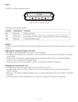
The top of the column is supplied with 4 M6 threaded holes meant for mounting onto the desk frame. We advise you to fasten
the desk frame by means of 4 pcs. M6 screws of a good quality (min. 8.8) and a suitable length, which must not go further
than max. 14 mm into the column. The thrust moment must not exceed 10 Nm.
Screw length
Min. B + 9 mm
Max. B + 14 mm

Page 13 of 40
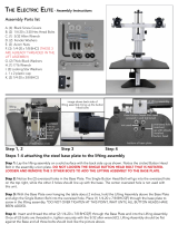
As the desktop amplifies the sound, we advise you to place a vibration/shock absorbing material between the desktop
and the desk frame.
Table top
Absorbing
material
Height of the DL in the lowest position
Min. desk height
Floor level
LINAK recommends that the DESKLINE
®
DL system should be used in push applications.
(Example of how to mount a 2-parallel DESKLINE
®
DL system)

Page 14 of 40
Mounted with 2 x M8
Mounted with 4 x M6
Mounting foot
The DL14 is supplied with 4 M6 threaded holes and 2 M8 screws for mounting of the foot. You can either use 2 M8 screws or
4 M6 screws dependent on your foot design. We advise you to use screws of a good quality min. 8.8 and of a suitable length,
which must not go further than 16 mm into the DL14 column. The thrust moment must not exceed 10 Nm in the bottom plate
thread.
The holes in the foot ought to be sufficiently larger than ø6 so that it is possible to bring the foot to a level line at assembly/
mounting of the table.

Page 15 of 40
Mounting guidelines for the DL12
Mounting the feet
The DL12 bottom plate is supplied with four M6 threaded holes.
1. Mount column bottom on desk feet using four M6 bolts with
the following specifications:
Quality: Min. grade 8.8
Length: Min. 12 mm (plus desk feet thickness);
Max. 16 mm (plus desk feet thickness)
2. Fasten bolts thoroughly (torque: max. 10 Nm).
The holes in the foot must be sufficiently larger than ø6 to
enable levelling of the assembled desk.
Mounting the top
The DL12 top plate is supplied with four M6 threaded
holes for mounting onto the top frame.
1. Mount column top on top frame using four M6 bolts
with the following specifications:
Quality: Min. grade 8.8
Length: Min. 12 mm (plus top frame thickness);
Max. 16 mm (plus top frame thickness)
2. Fasten bolts thoroughly (torque: max. 10 Nm).
Drawing No.: DL12_SKREWDEPTH
Min. 12mm
Drawing No.: DL12_SKREWDEPTH
Max. 16mm
SCALE 3:10
SECTION XSEC0001-XSEC0001
SEE DETAIL A
M6
Table top
Absorbing
material
Height of the DL in the lowest position
Min. desk height
Floor level
Mounting the desk
The sound from the lifting column spreads as vibrations to the tabletop which amplifies the sound. This can, however, be
reduced.
1. Place vibration/shock-absorbing material between tabletop and top frame.

Page 16 of 40
Mounting guidelines for the DL17 system
Mounting foot
The DL17 is supplied with 4 x M6 threaded holes and 2 x M8
screws for mounting of the foot. You can use either 2 x M8
screws or 4 x M6 screws dependent on your foot design. We
advise you to use screws of a good quality min. 8.8 and of
a suitable length, which must not go into the DL17 column
further than 16 mm. The screw torque must not exceed 10
Nm in the bottom plate thread.
The holes in the foot ought to be sufficiently larger than
(1) 6 so that it is possible to bring the foot to a level line at
assembly/mounting of the table.
Mounting top
The top of the column is supplied with 4 x M6 threaded
holes meant for mounting onto the desk frame . We advise
you to fasten the desk frame by means of 4 x M6 screws of
a good quality (min. 8.8) and a suitable length of minimum
10 mm and must not go into the column further than
maximum 14 mm. The screw torque must not exceed 10 Nm
Drawing No.: 0639075
Min 10 mm
Max. 16 mm
Min. 10 mm
Max. 16 mm
Min. 10 mm
Max. 14 mm
Drawing No.: 0639075
MC 6
MC 8
Bottom Plate
MC 6
Top Plate
Drawing No.: 0639075
Min 10 mm
Max. 16 mm
Min. 10 mm
Max. 16 mm
Min. 10 mm
Max. 14 mm
Drawing No.: 0639075
MC 6
MC 8
Bottom Plate
MC 6
Top Plate
As the desktop amplifies the sound, we advise you to place a vibration/shock absorbing material between the
desktop and the desk frame.
(Example of how to mount the DESKLINE
®
system)

Page 17 of 40
When mounting the DL17 to the tabletop and feet, we recommend orienting the column, so the cable is pointing in direction
of the centre of the desk.

Page 18 of 40
Mounting guidelines for the DB14
For detailed information on how to mount the DB14, please contact DESKLINE Technical Support at LINAK A/S.
Please note: The screws and rubber washers for mounting the DB14 in profiles must be ordered separately,
please contact DESKLINE Technical Support at LINAK A/S.
Example of an assembled DESKLINE
®
system
Mounting the top
The top of the motor is supplied with holes for the self-tapping special screws.
On the top of the motor there is the special rubber suspension, which should always be used when the DB14 is mounted in
a column. The rubber suspension is grey; a grey rubber suspension means no PIEZO. The top flange onto which the motor is
mounted must be 4 mm thick ±0.1 mm, and the two mounting holes should be ø12 mm with a centre distance of 36 mm.
The torque is 2 Nm ±0.1 Nm.
Special screws
Rubber washer
Rubber suspension
Motor

Page 19 of 40
From the factory, the DB14 is delivered with the hollow spindle driven into end position. Please observe that the
solid spindle may roll out during transportation/handling, but it must be rolled back to end position before mounting
in the profile.
As the desktop amplifies the sound,we advise you to place a vibration/shock absorbing material between the
desktop and the desk frame
Do not drive the DB14 to the outer end position before mounting. This will damage the DB.
Bottom plate with groove and spline
Mounting the middle tube
The DB14 gives the possibility of synchronous drive of the middle profile. To make sure that the profiles are in the
right place, you have to ensure that both the hollow and the solid spindle are driven into end position. For detailed
information on how to mount the middle tube of your column, please contact DESKLINE Technical Support at
LINAK A/S.
Mounting the bottom
At the bottom of the DB14 the inner spindle should be mounted by means of a 22 teeth spline profile and an M5 screw in the
bottom of the spindle. Max. torque: 2.3 Nm.
The bottom plate should have a groove for the locking ring.
A cut-out in the inner profile is required for cable relief.
Note:

Page 20 of 40
The CBD must not be packed in heat insulating material, but must be placed so that it can emit waste heat into the
surroundings. There are no ventilation holes to consider, the CBD emits heat through the surface.
The plug must be visible when the CBD is mounted so that the supply to the CBD can be disconnected at replacement, if any.
The mounting screws on the control box must be fastened with a max. torque of 1 Nm.
The mounting surface to which the control box is attached should have a surface evenness of better than ±0.5 mm.
Bottom with cable grooves
The bottom of the CBD6S (SMPS) is equipped with two cable grooves improving the cable management when mounting. The
grooves can be used to bypass the CBD for both motor cables and the mains cable (EU version only) from one side to the
other, giving a cleaner design.
Remember to lead the cables through the grooves before mounting the control box.
For mounting and operation of the desk panel, please see the separate user manual for desk panels.
Mounting guidelines for the CBD6S (SMPS)
The control box is to be fastened with 2 screws with a head diameter between ø 8 and ø 10 mm. With regard to the tension
surface ø 10 mm is preferable due to a lower surface tension. See drawing appendix for placing of mounting holes and the
space the CBD takes up.
CBD6S 200W and CBD6S 300W
Page is loading ...
Page is loading ...
Page is loading ...
Page is loading ...
Page is loading ...
Page is loading ...
Page is loading ...
Page is loading ...
Page is loading ...
Page is loading ...
Page is loading ...
Page is loading ...
Page is loading ...
Page is loading ...
Page is loading ...
Page is loading ...
Page is loading ...
Page is loading ...
Page is loading ...
Page is loading ...
-
 1
1
-
 2
2
-
 3
3
-
 4
4
-
 5
5
-
 6
6
-
 7
7
-
 8
8
-
 9
9
-
 10
10
-
 11
11
-
 12
12
-
 13
13
-
 14
14
-
 15
15
-
 16
16
-
 17
17
-
 18
18
-
 19
19
-
 20
20
-
 21
21
-
 22
22
-
 23
23
-
 24
24
-
 25
25
-
 26
26
-
 27
27
-
 28
28
-
 29
29
-
 30
30
-
 31
31
-
 32
32
-
 33
33
-
 34
34
-
 35
35
-
 36
36
-
 37
37
-
 38
38
-
 39
39
-
 40
40


Linak DESKLINE DL12XL User manual
- Type
- User manual
Ask a question and I''ll find the answer in the document
Finding information in a document is now easier with AI
Related papers


Other documents
-
 Coleshome Computer Desk 47", Modern Simple Style Desk for Home Office, Sturdy Writing Desk, , Black Installation guide
-
 RR Mechatronics Starrsed X-Clean Westergren Pipettes Operating instructions
-
Coremorrow Preloaded User manual
-
 Ergo Desktop ELEC-KE-MAP-27-30S Operating instructions
-
Jensen SMPS-560 User guide
-
 Coremorrow ZT50M14 User manual
-
Novus 961+2509+000 Datasheet
-
-
 Ergo Desktop ELEC-KE-MAP-27-30S Assembly Instructions
-
 ApexDesk AL4628-XX Electric Height Adjusted Sit to Stand Desk Owner's manual


