Page is loading ...

ba75865e08 06/2010
Multi 3430
Operating manual
Digital pH / D.O. /
conductivity meter
for 3 digital IDS sensors
pH

Multi 3430
2
ba75865e08 06/2010
Accuracy when
going to press
The use of advanced technology and the high quality standard of our instru-
ments are the result of a continuous development. This may result in differ-
ences between this operating manual and your meter. Also, we cannot
guarantee that there are absolutely no errors in this manual. Therefore, we
are sure you will understand that we cannot accept any legal claims resulting
from the data, figures or descriptions.
Copyright
© Weilheim 2010, WTW GmbH
Reproduction in whole - or even in part - is prohibited without the express writ-
ten permission of WTW GmbH, Weilheim.
Printed in Germany.

Multi 3430 Contents
3
Multi 3430 - Contents
ba75865e08 06/2010
1 Overview . . . . . . . . . . . . . . . . . . . . . . . . . . . . . . . . . . . . . 7
1.1 Keypad . . . . . . . . . . . . . . . . . . . . . . . . . . . . . . . . . . . . . . . 8
1.2 Display . . . . . . . . . . . . . . . . . . . . . . . . . . . . . . . . . . . . . . . 9
1.3 Socket field . . . . . . . . . . . . . . . . . . . . . . . . . . . . . . . . . . . 11
1.4 Automatic sensor recognition . . . . . . . . . . . . . . . . . . . . . 12
1.5 IDS sensors. . . . . . . . . . . . . . . . . . . . . . . . . . . . . . . . . . . 12
1.6 IDS adapter for analog sensors . . . . . . . . . . . . . . . . . . . 13
2 Safety . . . . . . . . . . . . . . . . . . . . . . . . . . . . . . . . . . . . . . . 15
2.1 Authorized use . . . . . . . . . . . . . . . . . . . . . . . . . . . . . . . . 16
2.2 General safety instructions . . . . . . . . . . . . . . . . . . . . . . . 16
3 Commissioning. . . . . . . . . . . . . . . . . . . . . . . . . . . . . . . 19
3.1 Scope of delivery. . . . . . . . . . . . . . . . . . . . . . . . . . . . . . . 19
3.2 Power supply. . . . . . . . . . . . . . . . . . . . . . . . . . . . . . . . . . 19
3.3 Initial commissioning . . . . . . . . . . . . . . . . . . . . . . . . . . . . 19
3.3.1 Inserting the rechargeable batteries. . . . . . . . . . 19
3.3.2 Connecting the power pack / charging the
batteries . . . . . . . . . . . . . . . . . . . . . . . . . . . . 20
3.3.3 Switching on the meter. . . . . . . . . . . . . . . . . . . . 21
3.3.4 Setting the date and time . . . . . . . . . . . . . . . . . 22
4 Operation. . . . . . . . . . . . . . . . . . . . . . . . . . . . . . . . . . . . 23
4.1 Switching on the meter . . . . . . . . . . . . . . . . . . . . . . . . . . 23
4.2 General operating principles . . . . . . . . . . . . . . . . . . . . . . 24
4.2.1 Operating modes . . . . . . . . . . . . . . . . . . . . . . . . 24
4.2.2 Display of several sensors in measuring mode . 25
4.2.3 Navigation . . . . . . . . . . . . . . . . . . . . . . . . . . . . . 26
4.2.4 Example 1 on navigation: Setting the language. 28
4.2.5 Example 2 on navigation: Setting the date and
time . . . . . . . . . . . . . . . . . . . . . . . . . . . . . . . . 30
4.3 Sensor-independent settings . . . . . . . . . . . . . . . . . . . . . 32
4.3.1 System . . . . . . . . . . . . . . . . . . . . . . . . . . . . . . . . 32
4.3.2 Data storage. . . . . . . . . . . . . . . . . . . . . . . . . . . . 34
4.3.3 Automatic Stability control . . . . . . . . . . . . . . . . . 34
4.4 Sensor info . . . . . . . . . . . . . . . . . . . . . . . . . . . . . . . . . . . 34
4.5 Channel display. . . . . . . . . . . . . . . . . . . . . . . . . . . . . . . . 35

Contents Multi 3430
4
ba75865e08 06/2010
4.6 pH value. . . . . . . . . . . . . . . . . . . . . . . . . . . . . . . . . . . . . . 36
4.6.1 General information . . . . . . . . . . . . . . . . . . . . . . 36
4.6.2 Measuring the pH value . . . . . . . . . . . . . . . . . . . 37
4.6.3 Settings for pH measurements . . . . . . . . . . . . . . 39
4.6.4 pH calibration . . . . . . . . . . . . . . . . . . . . . . . . . . . 42
4.6.5 Calibration interval . . . . . . . . . . . . . . . . . . . . . . . 47
4.6.6 Carrying out an automatic calibration (AutoCal) . 48
4.6.7 Carrying out a manual calibration (ConCal) . . . . 52
4.6.8 Displaying calibration records. . . . . . . . . . . . . . . 54
4.6.9 Continuous measurement control (CMC
function) . . . . . . . . . . . . . . . . . . . . . . . . . . . . . 56
4.6.10 QSC function (sensor quality control) . . . . . . 57
4.7 ORP voltage . . . . . . . . . . . . . . . . . . . . . . . . . . . . . . . . . . 60
4.7.1 General information . . . . . . . . . . . . . . . . . . . . . . 60
4.7.2 Measuring the ORP . . . . . . . . . . . . . . . . . . . . . . 60
4.7.3 Settings for ORP measurements . . . . . . . . . . . . 62
4.8 Dissolved oxygen. . . . . . . . . . . . . . . . . . . . . . . . . . . . . . . 63
4.8.1 General information . . . . . . . . . . . . . . . . . . . . . . 63
4.8.2 Measuring . . . . . . . . . . . . . . . . . . . . . . . . . . . . . . 64
4.8.3 Settings for D.O. sensors
(menu or measurement and calibration settings) 67
4.8.4 FDO
®
Check procedure (check of the FDO
®
925) . . . . . . . . . . . . . . . . . . . . . . . . . . . . . . . . 70
4.8.5 D.O. calibration . . . . . . . . . . . . . . . . . . . . . . . . . . 72
4.8.6 Displaying calibration records. . . . . . . . . . . . . . . 74
4.9 Conductivity . . . . . . . . . . . . . . . . . . . . . . . . . . . . . . . . . . . 75
4.9.1 General information . . . . . . . . . . . . . . . . . . . . . . 75
4.9.2 Measuring . . . . . . . . . . . . . . . . . . . . . . . . . . . . . . 75
4.9.3 Temperature compensation . . . . . . . . . . . . . . . . 78
4.9.4 Settings for IDS conductivity sensors . . . . . . . . . 79
4.9.5 Determining the cell constant
(calibration in control standard) . . . . . . . . . . . . . 82
4.9.6 Displaying calibration records. . . . . . . . . . . . . . . 84
4.10 Data storage . . . . . . . . . . . . . . . . . . . . . . . . . . . . . . . . . . 85
4.10.1 Manual storage . . . . . . . . . . . . . . . . . . . . . . . . . . 86
4.10.2 Automatic storage at intervals . . . . . . . . . . . . 86
4.10.3 Editing the measurement data storage. . . . . . . . 89
4.10.4 Erasing the measurement data storage . . . . . . . 90
4.11 Transmitting data (USB interfaces) . . . . . . . . . . . . . . . . . 91
4.11.1 Outputting current measurement data . . . . . . . . 91
4.11.2 Transmitting data (to a PC). . . . . . . . . . . . . . . . . 91
4.11.3 Connecting the PC / USB-B interface (USB
Device) . . . . . . . . . . . . . . . . . . . . . . . . . . . . . . 91
4.11.4 Options for data transmission to a PC (USB-B
interface). . . . . . . . . . . . . . . . . . . . . . . . . . . . . . . 92
4.11.5 Connecting the USB memory device / USB-A
interface (USB Host) . . . . . . . . . . . . . . . . . . . 93
4.11.6 Data transmission to a USB memory device
(USB-A interface) . . . . . . . . . . . . . . . . . . . . . . . . 93

Multi 3430 Contents
5
ba75865e08 06/2010
4.12 Reset. . . . . . . . . . . . . . . . . . . . . . . . . . . . . . . . . . . . . . . . 94
4.12.1 Resetting the measurement settings. . . . . . . . . 94
4.12.2 Resetting the system settings . . . . . . . . . . . . . . 96
5 Maintenance, cleaning, disposal. . . . . . . . . . . . . . . . . 97
5.1 Maintenance . . . . . . . . . . . . . . . . . . . . . . . . . . . . . . . . . . 97
5.1.1 Replacing the rechargeable batteries . . . . . . . . 97
5.2 Cleaning . . . . . . . . . . . . . . . . . . . . . . . . . . . . . . . . . . . . . 98
5.3 Packing . . . . . . . . . . . . . . . . . . . . . . . . . . . . . . . . . . . . . . 98
5.4 Disposal . . . . . . . . . . . . . . . . . . . . . . . . . . . . . . . . . . . . . 98
6 What to do if... . . . . . . . . . . . . . . . . . . . . . . . . . . . . . . . . 99
6.1 General information. . . . . . . . . . . . . . . . . . . . . . . . . . . . . 99
6.2 pH . . . . . . . . . . . . . . . . . . . . . . . . . . . . . . . . . . . . . . . . . 101
6.3 Dissolved oxygen . . . . . . . . . . . . . . . . . . . . . . . . . . . . . 102
6.4 Conductivity. . . . . . . . . . . . . . . . . . . . . . . . . . . . . . . . . . 103
7 Technical data. . . . . . . . . . . . . . . . . . . . . . . . . . . . . . . 105
7.1 General data . . . . . . . . . . . . . . . . . . . . . . . . . . . . . . . . . 105
7.2 Measuring ranges, resolution, accuracy . . . . . . . . . . . . 106
8 Lists . . . . . . . . . . . . . . . . . . . . . . . . . . . . . . . . . . . . . . . 107
9 Appendix: Firmware update. . . . . . . . . . . . . . . . . . . . 111
9.1 Firmware update for the meter Multi 3430 . . . . . . . . . . 111
9.2 Firmware-Update for IDS Sensors . . . . . . . . . . . . . . . . 112

Contents Multi 3430
6
ba75865e08 06/2010

Multi 3430 Overview
7
ba75865e08 06/2010
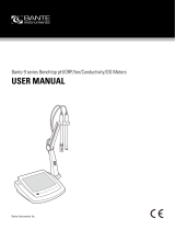
1Overview
The compact, digital precision meter Multi 3430 enables you to carry
out pH measurements, ORP measurements, conductivity measure-
ments and dissolved oxygen (D.O.) measurements quickly and reliably.
The Multi 3430 provides the maximum degree of operating comfort,
reliability and measuring certainty for all applications.
The Multi 3430 supports you in your work with the following functions:
z proven calibration procedures
z automatic stability control (AR),
z automatic sensor recognition,
z CMC (continuous measurement control)
z QSC (sensor quality control).
1 Keypad
2 Display
3 Socket field
1
2
3
pH

Overview Multi 3430
8
ba75865e08 06/2010
The two USB interfaces (USB-A and USB-B) enable you to:
z Transmit data to
– a USB memory device
–a PC
z Update the meter firmware.
1.1 Keypad
In this operating manual, keys are indicated by brackets <..> .
The key symbol (e.g. <MENU/ENTER>) generally indicates a short
keystroke (under 2 sec) in this operating manual. A long keystroke
(approx. 2 sec) is indicated by the underscore behind the key symbol
(e.g. <MENU/ENTER
_>).
M
F1
F2
ARCAL
PRT ESCRCLSTO
MENU
ENTER
MENU
ENTER
Multi 3430
<F1>:
<F2>:
Softkeys providing situation dependent functions, e.g.:
<F1>/[Info]: View information on a sensor
<On/Off>: Switches the meter on or off
<M>: Selects the measured parameter
<CAL>:
<CAL
_>:
Calls up the calibration procedure
Displays the calibration data
<AR> Freezes the measured value (HOLD function)
Switches the AutoRead measurement on or off
F1
F2
CAL
ARAR

Multi 3430 Overview
9
ba75865e08 06/2010
1.2 Display
<STO>:
<STO
_>:
Saves a measured value manually
Opens the menu for the automatic save function
<RCL>:
<RCL
_>:
Displays the manually stored measured values
Displays the automatically stored measured values
<S><T>:
<W><X>:
Menu control, navigation
<MENU/ENTER>:
<MENU/ENTER
_>:
Opens the menu for measurement settings / Confirms
entries
Opens the menu for system settings
<PRT>
<PRT
_>
Outputs stored data to the interface
Outputs displayed data to the interface in intervals
MENU
ENTER
MENU
ENTER
PRT
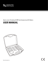
1 Status information
2 Measured value (with unit)
3 Measured parameter
4 Continuous measurement control (CMC function)
5 Channel display:
Plug position of the sensor
6 Sensor symbol (calibration evaluation, calibration interval)
7 Measured temperature (with unit)
8 Softkeys and date + time
3
2
1
4
6
7
8
5
22.09.2009 08:00
Info

Overview Multi 3430
10
ba75865e08 06/2010
Function display
indicators
AutoCal
e.g. TEC
Calibration with automatic buffer recognition, e.g.
with the buffer set: Technical buffers
ConCal Calibration with any buffers
Error An error occurred during calibration
AR Stability control (AutoRead) is active
HOLD Measured value is frozen (<AR> key)
Batteries are almost empty
Mains operation
Mains operation with charge function
Batteries are automatically charged in the back-
ground.
Data are automatically output to the USB-B inter-
face at intervals
Data are output to the USB-A interface (USB flash
drive)
Power supply via the USB-B interface
Batteries are not being charged

Multi 3430 Overview
11
ba75865e08 06/2010
1.3 Socket field
CAUTION
Only connect sensors to the meter that cannot return any voltages
or currents that are not allowed (> SELV and > current circuit with
current limiting).
WTW IDS sensors and IDS adapters meet these requirements.
Connectors:
1
Digital sensors
(pH, ORP, conductivity, D.O.)
2 Power pack
3 USB-A (host) interface
4 USB B (device) interface
5 Service interface
5
1
2
3
4

Overview Multi 3430
12
ba75865e08 06/2010
1.4 Automatic sensor recognition
The automatic sensor recognition for IDS sensors allows
z to operate an IDS sensor at different meters without recalibration
z to operate different IDS sensors at one meter without recalibration
z to assign measurement data to an IDS sensor
– Measurement datasets are always stored and output with the
sensor name and sensor series number.
z to assign calibration data to an IDS sensor
– Calibration data and calibration history are always stored and
output with the sensor name and sensor series number.
z to activate the correct cell constant for conductivity sensors auto-
matically
z to hide menus automatically that do not concern this sensor
To be able to use the automatic sensor recognition, a meter that sup-
ports the automatic sensor recognition (e.g. Multi 3430) and a digital
IDS sensor are required.
In digital IDS sensors, sensor data are stored that clearly identify the
sensor.
The sensor data are automatically taken over by the meter.
1.5 IDS sensors
IDS sensors
z support the automatic sensor recognition
z show only the settings relevant to the specific sensor in the setting
menu
z process signals in the sensor digitally so that precise and interfer-
ence-free measurements are enabled even with long cables
z facilitate to assign a sensor to a measured parameter with differently
colored couplings
z have quick-lock couplings with which to fix the sensors to the meter.
Note
Information on available IDS sensors is given on the Internet and in
the WTW catalog, "Laboratory and field instrumentation".

Multi 3430 Overview
13
ba75865e08 06/2010
Sensor data from IDS
sensors
IDS sensors transmit the following sensor data to the meter:
z SENSOR ID
– Sensor name
– Sensor series number
z Calibration data
– Calibration date
– Calibration characteristics
– Calibration interval
– Selected buffer set (IDS pH sensors only)
– Cell constant (IDS conductivity sensors only)
– Calibration history of the last 10 calibrations
z Measurement settings (IDS conductivity sensors only)
– The set measured parameter
– The set reference temperature
– The set temperature coefficient
– The set TDS factor
The calibration data are updated in the IDS sensor after each calibra-
tion procedure. A message is displayed while the data are being
updated in the sensor.
1.6 IDS adapter for analog sensors
With the aid of an IDS adapter, you can also operate analog sensors
on the Multi 3430. An IDS adapter and analog sensor together behave
like an IDS sensor.
The measuring electronics with the stored adapter data are in the
adapter head. The adapter data correspond to the sensor data.
Note
In the measured value display, you can display the sensor name and
series number of the selected sensor with the [Info] softkey. You can
then display all further sensor data stored in the sensor with the [More]
softkey.
Note
Information on available IDS adapters is given on the Internet and in
the WTW catalog, "Laboratory and field instrumentation".
Detailed information on the IDS adapter is given in the operating man-
ual of the adapter.

Overview Multi 3430
14
ba75865e08 06/2010

Multi 3430 Safety
15
ba75865e08 06/2010
2 Safety
This operating manual contains basic instructions that you must follow
during the commissioning, operation and maintenance of the meter.
Consequently, all responsible personnel must read this operating man-
ual before working with the meter.
The operating manual must always be available within the
vicinity of the meter.
Target group The meter was developed for work in the field and in the laboratory.
Thus, we assume that, as a result of their professional training and
experience, the operators will know the necessary safety precautions
to take when handling chemicals.
Safety instructions Safety instructions in this operating manual are indicated by the warn-
ing symbol (triangle) in the left column. The signal word (e.g. "Caution")
indicates the level of danger:
WARNING
indicates instructions that must be followed precisely in order to
avoid possibly great dangers to personnel.
CAUTION
indicates instructions that must be followed precisely in order to
avoid the possibility of slight injuries or damage to the meter or
the environment.
Further notes
Note
indicates notes that draw your attention to special features.
Note
indicates cross-references to other documents, e.g. operating manu-
als.

Safety Multi 3430
16
ba75865e08 06/2010
2.1 Authorized use
The authorized use of the meter consists exclusively of the measure-
ment of the pH, ORP, conductivity and dissolved oxygen in a field and
laboratory environment.
The technical specifications as given in chapter 7 T
ECHNICAL DATA must
be observed. Only the operation and running of the meter according to
the instructions given in this operating manual is authorized.
Any other use is considered unauthorized.
2.2 General safety instructions
This meter is constructed and tested in compliance with the IEC 1010
safety regulations for electronic measuring instruments.
It left the factory in a safe and secure technical condition.
Function and
operational safety
The smooth functioning and operational safety of the meter can only be
guaranteed if the generally applicable safety measures and the specific
safety instructions in this operating manual are followed during opera-
tion.
The smooth functioning and operational safety of the meter can only be
guaranteed under the environmental conditions that are specified in
chapter 7 T
ECHNICAL DATA.
If the meter was transported from a cold environment to a warm envi-
ronment, the formation of condensate can lead to the faulty functioning
of the meter. In this event, wait until the temperature of the meter
reaches room temperature before putting the meter back into opera-
tion.
CAUTION
The meter is only allowed to be opened by authorized personnel.

Multi 3430 Safety
17
ba75865e08 06/2010
Safe operation If safe operation is no longer possible, the meter must be taken out of
service and secured against inadvertent operation!
Safe operation is no longer possible if the meter:
z has been damaged in transport
z has been stored under adverse conditions for a lengthy period of
time
z is visibly damaged
z no longer operates as described in this manual.
If you are in any doubt, please contact the supplier of the meter.
Obligations of the
purchaser
The purchaser of this meter must ensure that the following laws and
guidelines are observed when using dangerous substances:
z EEC directives for protective labor legislation
z National protective labor legislation
z Safety regulations
z Safety datasheets of the chemical manufacturers.
CAUTION
In addition to the safety instructions mentioned here, also follow
the safety instructions of the sensors used.
The operating manuals of the sensors are available on the sup-
plied CD and on the Internet under www.WTW.com.

Safety Multi 3430
18
ba75865e08 06/2010

Multi 3430 Commissioning
19
ba75865e08 06/2010
3 Commissioning
3.1 Scope of delivery
z Meter Multi 3430
z 4 NiMH rechargeable batteries 1.2 V Mignon type AA
z USB cable (A plug on mini B plug)
z Power pack
z Short instructions
z Detailed operating manual (4 languages)
z CD-ROM
3.2 Power supply
The Multi 3430 is supplied with power in the following ways:
z Battery operation with NiMh rechargeable batteries
z Mains operation with the supplied power pack.
The NiMh rechargeable batteries are automatically charged while
the power pack is connected.
z USB operation via a connected USB-B cable.
The inserted NiMh rechargeable batteries are not charged
3.3 Initial commissioning
Perform the following activities:
z Insert the rechargeable batteries and charge them
z Connect the power pack (mains operation / battery charging)
z Switch on the meter
z Set the date and time
3.3.1 Inserting the rechargeable batteries
1 Unscrew the two screws (1) on the underside of the meter.
2 Open the battery compartment (2) on the underside of the
meter.

Commissioning Multi 3430
20
ba75865e08 06/2010
CAUTION
Make sure that the poles of the rechargeable batteries are posi-
tioned correctly.
The
± signs on the batteries must correspond to the ± signs in the
battery compartment.
3.3.2 Connecting the power pack / charging the batteries
CAUTION
The line voltage at the operating site must lie within the input volt-
age range of the original power pack (see section 7.1).
CAUTION
Use original power packs only (see section 7.1).
CAUTION
The batteries in the battery compartment are automatically
charged when the power pack is connected.
Make sure that only NiMH rechargeable batteries are in the battery
compartment. The charging process is optimized for NiMH re-
chargeable batteries. Other battery types can cause damage dur-
ing the charging process.
3 Place four rechargeable batteries (type Mignon AA) in the bat-
tery compartment.
4 Close the battery compartment (2) and tighten the screws (1).
2
1
/