Page is loading ...

IGLOO PLUS Starter Kit
User’s Guide


IGLOO PLUS Starter Kit User’s Guide
Revision 1 3
Table of Contents
Introduction . . . . . . . . . . . . . . . . . . . . . . . . . . . . . . . . . . . . . . . . . . . . . . . . . . . . . . . . . . . . . . . . . . . . . . 5
IGLOO PLUS Starter Kit Contents . . . . . . . . . . . . . . . . . . . . . . . . . . . . . . . . . . . . . . . . . . . . . . . . . . . . . . . . . . . . . . 5
1 Board Components and Settings . . . . . . . . . . . . . . . . . . . . . . . . . . . . . . . . . . . . . . . . . . . . . . . . . . . . . . 7
Board Description . . . . . . . . . . . . . . . . . . . . . . . . . . . . . . . . . . . . . . . . . . . . . . . . . . . . . . . . . . . . . . . . . . . . . . . . . . 7
IGLOO PLUS Board Stackup . . . . . . . . . . . . . . . . . . . . . . . . . . . . . . . . . . . . . . . . . . . . . . . . . . . . . . . . . . . . . . . . . . 8
Connectors, Jumpers, and Switch Settings . . . . . . . . . . . . . . . . . . . . . . . . . . . . . . . . . . . . . . . . . . . . . . . . . . . . . . 11
2 FPGA Description. . . . . . . . . . . . . . . . . . . . . . . . . . . . . . . . . . . . . . . . . . . . . . . . . . . . . . . . . . . . . . . . . 15
Key Features of AGLP125-CSG289 . . . . . . . . . . . . . . . . . . . . . . . . . . . . . . . . . . . . . . . . . . . . . . . . . . . . . . . . . . . 15
Power and Ground Pins . . . . . . . . . . . . . . . . . . . . . . . . . . . . . . . . . . . . . . . . . . . . . . . . . . . . . . . . . . . . . . . . . . . . . 16
JTAG Pins . . . . . . . . . . . . . . . . . . . . . . . . . . . . . . . . . . . . . . . . . . . . . . . . . . . . . . . . . . . . . . . . . . . . . . . . . . . . . . . 20
Decaps and Ground Post Schematics . . . . . . . . . . . . . . . . . . . . . . . . . . . . . . . . . . . . . . . . . . . . . . . . . . . . . . . . . . 21
3 Power . . . . . . . . . . . . . . . . . . . . . . . . . . . . . . . . . . . . . . . . . . . . . . . . . . . . . . . . . . . . . . . . . . . . . . . . . . 23
Power Modes . . . . . . . . . . . . . . . . . . . . . . . . . . . . . . . . . . . . . . . . . . . . . . . . . . . . . . . . . . . . . . . . . . . . . . . . . . . . . 24
Battery . . . . . . . . . . . . . . . . . . . . . . . . . . . . . . . . . . . . . . . . . . . . . . . . . . . . . . . . . . . . . . . . . . . . . . . . . . . . . . . . . . 25
Potentiometer and Voltage-Sweep . . . . . . . . . . . . . . . . . . . . . . . . . . . . . . . . . . . . . . . . . . . . . . . . . . . . . . . . . . . . 25
Current Measurement . . . . . . . . . . . . . . . . . . . . . . . . . . . . . . . . . . . . . . . . . . . . . . . . . . . . . . . . . . . . . . . . . . . . . . 26
4 Operation of Board Components . . . . . . . . . . . . . . . . . . . . . . . . . . . . . . . . . . . . . . . . . . . . . . . . . . . . . 29
Clock Oscillator . . . . . . . . . . . . . . . . . . . . . . . . . . . . . . . . . . . . . . . . . . . . . . . . . . . . . . . . . . . . . . . . . . . . . . . . . . . 29
Reset . . . . . . . . . . . . . . . . . . . . . . . . . . . . . . . . . . . . . . . . . . . . . . . . . . . . . . . . . . . . . . . . . . . . . . . . . . . . . . . . . . . 29
Flash*Freeze Mode . . . . . . . . . . . . . . . . . . . . . . . . . . . . . . . . . . . . . . . . . . . . . . . . . . . . . . . . . . . . . . . . . . . . . . . . 30
Push-Button Switches . . . . . . . . . . . . . . . . . . . . . . . . . . . . . . . . . . . . . . . . . . . . . . . . . . . . . . . . . . . . . . . . . . . . . . 37
.DIP Switches . . . . . . . . . . . . . . . . . . . . . . . . . . . . . . . . . . . . . . . . . . . . . . . . . . . . . . . . . . . . . . . . . . . . . . . . . . . . . 38
User LEDs . . . . . . . . . . . . . . . . . . . . . . . . . . . . . . . . . . . . . . . . . . . . . . . . . . . . . . . . . . . . . . . . . . . . . . . . . . . . . . . 39
I/O Test Pins . . . . . . . . . . . . . . . . . . . . . . . . . . . . . . . . . . . . . . . . . . . . . . . . . . . . . . . . . . . . . . . . . . . . . . . . . . . . . 40
OLED . . . . . . . . . . . . . . . . . . . . . . . . . . . . . . . . . . . . . . . . . . . . . . . . . . . . . . . . . . . . . . . . . . . . . . . . . . . . . . . . . . . 41
Interface Connector . . . . . . . . . . . . . . . . . . . . . . . . . . . . . . . . . . . . . . . . . . . . . . . . . . . . . . . . . . . . . . . . . . . . . . . . 42
USB-to-UART Interface . . . . . . . . . . . . . . . . . . . . . . . . . . . . . . . . . . . . . . . . . . . . . . . . . . . . . . . . . . . . . . . . . . . . . 42
SPI Flash . . . . . . . . . . . . . . . . . . . . . . . . . . . . . . . . . . . . . . . . . . . . . . . . . . . . . . . . . . . . . . . . . . . . . . . . . . . . . . . . 43
Low-Cost Programming Stick (LCPS) . . . . . . . . . . . . . . . . . . . . . . . . . . . . . . . . . . . . . . . . . . . . . . . . . . . . . . . . . . 44
5 Programming . . . . . . . . . . . . . . . . . . . . . . . . . . . . . . . . . . . . . . . . . . . . . . . . . . . . . . . . . . . . . . . . . . . . 49
6 IGLOO PLUS Board Demo . . . . . . . . . . . . . . . . . . . . . . . . . . . . . . . . . . . . . . . . . . . . . . . . . . . . . . . . . 51
Demos Included in the Starter Kit . . . . . . . . . . . . . . . . . . . . . . . . . . . . . . . . . . . . . . . . . . . . . . . . . . . . . . . . . . . . . 51
Powering Up the Board . . . . . . . . . . . . . . . . . . . . . . . . . . . . . . . . . . . . . . . . . . . . . . . . . . . . . . . . . . . . . . . . . . . . . 51
Getting Started with the IGLOO PLUS Starter Kit Demo Design . . . . . . . . . . . . . . . . . . . . . . . . . . . . . . . . . . . . . . 51
A Resources . . . . . . . . . . . . . . . . . . . . . . . . . . . . . . . . . . . . . . . . . . . . . . . . . . . . . . . . . . . . . . . . . . . . . . 55
B List of Changes . . . . . . . . . . . . . . . . . . . . . . . . . . . . . . . . . . . . . . . . . . . . . . . . . . . . . . . . . . . . . . . . . . 57

Table of Contents
4 Revision 1
C Product Support . . . . . . . . . . . . . . . . . . . . . . . . . . . . . . . . . . . . . . . . . . . . . . . . . . . . . . . . . . . . . . . . . . 59
Customer Service . . . . . . . . . . . . . . . . . . . . . . . . . . . . . . . . . . . . . . . . . . . . . . . . . . . . . . . . . . . . . . . . . . . . . . . . . 59
Customer Technical Support Center . . . . . . . . . . . . . . . . . . . . . . . . . . . . . . . . . . . . . . . . . . . . . . . . . . . . . . . . . . . 59
Technical Support . . . . . . . . . . . . . . . . . . . . . . . . . . . . . . . . . . . . . . . . . . . . . . . . . . . . . . . . . . . . . . . . . . . . . . . . . 59
Website . . . . . . . . . . . . . . . . . . . . . . . . . . . . . . . . . . . . . . . . . . . . . . . . . . . . . . . . . . . . . . . . . . . . . . . . . . . . . . . . . 59
Contacting the Customer Technical Support Center . . . . . . . . . . . . . . . . . . . . . . . . . . . . . . . . . . . . . . . . . . . . . . . 59
ITAR Technical Support . . . . . . . . . . . . . . . . . . . . . . . . . . . . . . . . . . . . . . . . . . . . . . . . . . . . . . . . . . . . . . . . . . . . . 60
Index . . . . . . . . . . . . . . . . . . . . . . . . . . . . . . . . . . . . . . . . . . . . . . . . . . . . . . . . . . . . . . . . . . . . . . . . . . 61

Revision 1 5
Introduction
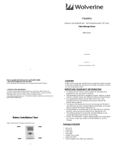
IGLOO PLUS Starter Kit Contents
The RoHS-compliant, environmentally friendly IGLOO® PLUS Starter Kit is packaged in a recyclable
cardboard box made from recycled materials. This development kit includes an on-board programmer
and demonstrates the ultra-low power of Microsemi
®
IGLOO PLUS devices. Table 1 lists the contents of
the box.
Table 1 • IGLOO PLUS Starter Kit Contents
Quantity Contents
1 IGLOO PLUS board with AGLP125 IGLOO PLUS field programmable gate array (FPGA)
1 Programmer for use with IGLOO PLUS board
1 5 V power supply
2 USB 2.0 high-speed cables
1 Packet of jumpers
1 Microsemi Libero
®
System-on-Chip (SoC) software DVD
1 Quickstart Guide
Figure 1 • IGLOO PLUS Starter Kit Board


Revision 1 7
1 – Board Components and Settings
This chapter describes the components and settings for the IGLOO PLUS Starter Kit Board.
Board Description
The IGLOO PLUS Starter Kit board is intended to provide a low-cost system platform for evaluating
IGLOO PLUS (AGLP) technology, such as low power, I/O state preservation during Flash*Freeze mode,
and Schmitt Triggered I/Os. Other advanced features include the ability to use the FPGA I/Os of the
Expansion Header as hot-swappable and the Schmitt Triggered FPGA inputs for improved noise
immunity.
This evaluation board enables you to measure power consumption (dynamic, static, and Flash*Freeze
modes) with the core operating between 1.2 V and 1.5 V. When using the board in conjunction with the
Microsemi power analysis tools, you will have a clear picture of application power consumption at each
stage in your design. In addition, the Libero SoC tool suite now includes power-driven layout (PDL),
which can reduce the power consumption of designs up to 30 percent.
The evaluation board has a small form factor, measuring 3.7 inches by 4 inches, and supports an
AGLP125 IGLOO PLUS device in the 14 mm × 14 mm CSG289 package. All components used on the
board, such as LEDs, reset (µA range), and oscillator, are low-power components. Also included on the
evaluation board is a USB-to-UART interface to allow HyperTerminal on a PC to communicate with the
IGLOO PLUS device on the board.
The top of the board has a programming stick header which allows the low-cost programming stick
LCPS) to be attached to the board for programming the IGLOO PLUS AGLP125-CSG289 device
(Figure 1-1). FPGA I/Os have been wired to test pin pads on the board for debug and expandability.
Note: The clock oscillator for the IGLOO PLUS Starter Kit Board is behind the board.
Figure 1-1 • IGLOO PLUS Starter Kit Board

Board Components and Settings
8 Revision 1
IGLOO PLUS Board Stackup
The IGLOO PLUS board is built on a 10-layer PCB. Figure 1-1 and Figure 1-1 on page 7 show the top
(L1) and bottom (L10) silkscreens. The full PCB design layout is provided on the Microsemi SoC
Products Group website, on the IGLOO PLUS Starter Kit page:
www.microsemi.com/soc/products/hardware/devkits_boards/iglooplus_starter.aspx. To view the PCB
design layout files, you can use the Allegro Free Physical Viewer, which can be downloaded from the
Cadence Allegro Downloads page.
• Top Signal (Figure 1-1 on page 7)
•GND 1
•Signal
•GND 2
•PWR 1
•PWR 2
•GND 3
•Signal
•GND 4
• Bottom Signal (Figure 1-2 on page 9)

IGLOO PLUS Starter Kit User’s Guide
Revision 1 9
Figure 1-2 • IGLOO PLUS Top Silkscreen (L1)

Board Components and Settings
10 Revision 1
Figure 1-3 • IGLOO PLUS Bottom Silkscreen (L10)

IGLOO PLUS Starter Kit User’s Guide
Revision 1 11
Connectors, Jumpers, and Switch Settings
Recommended default jumper settings are defined in Table 1-1. The voltage selection jumpers are
highlighted in grey. Connect jumpers in the default settings described in Tab le 1 -1 to enable the pre-
programmed demo design to function correctly.
Table 1-1 • Jumper and Connector Settings
Jumper Default Setting Comment
J1 Ground post header
J2 Ground post header
J3 LC JTAG header for programmer
J4 JTAG header
J5 USB mini receptacle
J6 Pin 2-3 Remove jumper to disconnect VCCI_0 power
J7 Remove Remove jumper to disconnect external battery source
J8 Pin 2-3 Remove jumper to disconnect VCCI_1 power
J9 Pin 1-4 Select WALL, BAT, VUSB for 5V_SOURCE
Pin 1-4 = VUSB
Pin 2-4 = BAT
Pin 3-4 = WALL
J10 5 V Brick
J11 Pin 1-2 Select VCC or VCC_SWEEP for VCORE
Pin 1-2 = VCC
Pin 3-2 = VCC_SWEEP
J12 Pin 2-3 Current measurement header for VCORE
J13 Pin 2-3 Current measurement header for VCCI_3
J14 Pin 1-2 Select VCC or VCC_SWEEP for VCCI_1
Pin 1-2 = VCC
Pin 3-2 = VCC_SWEEP
J15 Pin 3-2 Select VJTAGENB or 3.3 V
Pin 3-2 = VJTAGENB
Pin 1-2 = 3.3 V
J16 Pin 2-4 Select 3.3 V, 1.5 / 1.2 V, or 2.5 V for VCCI_1
Pin 2-4 = 3.3 V
Pin 3-4 = 1.5 V or 1.2 V
Pin 1-4 = 2.5 V
J17 Pin 2-3 Current measurement header for VCCI_2
J18 Pin 1-2 Select VCC or VCC_SWEEP for VCCI_0
Pin 1-2 = VCC
Pin 3-2 = VCC_SWEEP

Board Components and Settings
12 Revision 1
J19 Pin 2-4 Select 3.3 V, 1.5 / 1.2 V, or 2.5 V for VCCI_0
Pin 2-4 = 3.3 V
Pin 3-4 = 1.5 V or 1.2 V
Pin 1-4 = 2.5 V
J20 Pin 2-3 Current measurement header for VJTAG
J21 Pin 1-2 Select 3.3 V or 1.5 / 1.2 V for VJTAG
Pin 1-2 = 3.3 V
Pin 2-3 = 1.5 V or 1.2 V
J22 Pin 2-3 Current measurement header for VPUMP
J23-J24 Pin 1-2 Remove each jumper to disconnect any of the 2 FET Switches[1:2] from
FPGA.
J23 = 3V3_SWITCH1
J24 = 3V3_SWITCH2
J25-J27 Pin 1-2 Remove each jumper to disconnect any of the 3 FET LEDs from FPGA.
J25 = FET_P1
J26 = FET_N
J27 = FET_P2
J28-J35 Pin 1-2 Remove each jumper to disconnect any of the 8 user DIP switches[1:8] from
FPGA.
J28 = D_SWITCH1
J29 = D_SWITCH2
J30 = D_SWITCH3
J31 = D_SWITCH4
J32 = D_SWITCH5
J33 = D_SWITCH6
J34 = D_SWITCH7
J35 = D_SWITCH8
J36-J39 Pin 1-2 Remove each jumper to disconnect any of the 4 push-button switches[1:4] from
FPGA.
J36 = SWITCH1
J37 = SWITCH2
J38 = SWITCH3
J39 = SWITCH4
J40-J47 Pin 1-2 Remove each jumper to disconnect any of the 8 user LEDs[1:8] from FPGA.
J42 = LED1
J41 = LED2
J40 = LED3
J47 = LED4
J46 = LED5
J45 = LED6
J44 = LED7
J43 = LED8
Table 1-1 • Jumper and Connector Settings (continued)
Jumper Default Setting Comment

IGLOO PLUS Starter Kit User’s Guide
Revision 1 13
Table 1-2 • Switch Settings
Switch Default Setting Comment
SW1–SW4 Push-button switches for SWITCH[1:4]
SW5 CLOSE Contains DIP switches for 3V3_SWITCH[1:2]
DSW5 CLOSE Contains DIP switches for D_SWITCH[1:8]
SW7 Push-button switch for system reset PBRESET_N
SW8 OFF Flash*Freeze: To enable Flash*Freeze mode, SW8 toward ON.
In Flash*Freeze mode, current consumption of FPGA goes below 50 µA.


Revision 1 15
2 – FPGA Description
The IGLOO PLUS board is populated with an IGLOO PLUS AGLP125-CSG289 FPGA.
Key Features of AGLP125-CSG289
• Low power
• 1.2 V to 1.5 V core voltage support for low power
• Supports single-voltage system operation
• 5 µW power consumption in Flash*Freeze mode
• Low-power active FPGA operation
• Flash*Freeze technology enables ultra-low power consumption while maintaining FPGA content
• Configurable hold previous state, tristate, HIGH, or LOW state per I/O in Flash*Freeze mode
• Easy entry to / exit from ultra-low-power Flash*Freeze mode
• Reprogrammable flash technology
• In-system programming (ISP) and security
• High-performance routing hierarchy
• Advanced I/O
• Selectable Schmitt trigger inputs
• Clock conditioning circuit (CCC) and PLL
• Embedded memory
Table 2-1 lists specifications for the AGLP125-CSG289 FPGA.
For further information, refer to the IGLOO PLUS datasheet:
www.microsemi.com/soc/documents/IGLOOPLUS_DS.pdf
Table 2-1 • IGLOO PLUS AGLP125-CSG289 FPGA Features
Feature Specification
System Gates 125,000
Typical Equivalent Macrocells 1,024
VersaTiles (D-flip-flops) 3,120
Flash*Freeze Mode (Typical, µW) 16
RAM kbits (1,024 bits) 36
4,608-Bit Blocks 8
FlashROM (bits) 1 K
Secure (AES) ISP Yes
Integrated PLLs in CCCs 1
VersaNet Globals 18
I/O Banks 4
Maximum User I/Os 212

FPGA Description
16 Revision 1
Power and Ground Pins
Figure 2-1 shows the power and ground pins for AGLP125-CSG289.
Figure 2-1 • Power and Ground Pins for AGLP125-CSG289
VCCPLF
VCCIB0_1
B7
VCCIB0_2
B12
VCCIB0_3
C5
VCCIB0_4
E11
VCCIB1_1
E16
VCCIB1_2
H15
VCCIB1_3
L14
VCCIB1_4
M17
VCCIB2_1
N10
VCCIB2_2
P13
VCCIB2_3
R6
VCCIB2_4
T9
VCCIB3_1
E1
VCCIB3_2
F4
VCCIB3_3
J3
VCCIB3_4
M2
VCC1
L9
VCC2
G9
VCC3
J7
VCC4
J11
VCOMPLF
H1
VCCPLF
J1
GND1
A4
GND2
A9
GND3
A14
GND4
B2
GND5
B17
GND6
C10
GND7
C15
GND8
D3
GND9
D8
GND10
D13
GND11
F14
GND12
G2
GND13
G7
GND14
G8
GND15
G10
GND16
G11
GND17
G17
GND18
H7
GND19
H8
GND20
H9
GND21
H10
GND22
H11
GND23
J8
GND24
J9
GND25
J10
GND26
K1
GND27
K7
GND28
K8
GND29
K9
GND30
K10
GND31
K11
GND32
K16
GND33
L4
GND34
L7
GND35
L8
GND36
L10
GND37
L11
GND38
N5
GND39
N15
GND40
P3
GND41
P8
GND42
R1
GND43
R11
GND44
T4
GND45
T14
GND46
U2
GND47
U7
GND48
U12
SEC 5/6
AGLP125 CSG289
POWER
GND
U5E
AGLP125-CSG289
SEC 5/6
POWER
GND
U5E

IGLOO PLUS Starter Kit User’s Guide
Revision 1 17
Bank I/O Signals
Figure 2-2 through Figure 2-5 on page 19 show the schematics for the bank I/O signals.
Figure 2-2 • Bank 0 I/O Signals for AGLP125-CSG289
AGL_B0_PIN_D5
AGL_B0_PIN_A3
AGL_B0_PIN_A2
AGL_B0_PIN_D6
AGL_B0_PIN_F7
AGL_B0_PIN_B4
AGL_B0_PIN_C6
AGL_B0_PIN_E7
AGL_B0_PIN_F8
AGL_B0_PIN_A5
AGL_B0_PIN_C7
AGL_B0_PIN_E8
AGL_B0_PIN_A7
AGL_B0_PIN_F9
AGL_B0_PIN_A8
AGL_B0_PIN_E9
AGL_B0_PIN_D9
AGL_B0_PIN_E10
AGL_B0_PIN_D12
AGL_B0_PIN_E12
AGL_B0_PIN_E5
AGL_B0_PIN_C16
AGL_B0_PIN_A1
AGL_B0_PIN_E13
AGL_B0_PIN_B16
AGL_B0_PIN_D14
AGL_B0_PIN_B3
AGL_B0_PIN_C4
AGL_B0_PIN_E6
AGL_B0_PIN_B5
AGL_B0_PIN_D7
AGL_B0_PIN_B6
AGL_B0_PIN_A6
AGL_B0_PIN_C8
AGL_B0_PIN_C2
AGL_B0_PIN_C3
AGL_B0_PIN_D15
AGL_B0_PIN_A17
AGL_B0_PIN_D4
AGL_B0_PIN_B1
AGL_B0_PIN_F10
AGL_B0_PIN_B9
AGL_B0_PIN_B8
AGL_B0_PIN_C9
AGL_B0_PIN_A10
AGL_B0_PIN_B10
GPIOA_29 {3}
GPIOA_33 {3}
GPIOA_31 {3}
GPIOA_35 {3}
GPIOA_9 {3}
GPIOA_13 {3}
GPIOA_15 {3}
GPIOA_17 {3}
GPIOA_19 {3}
GPIOA_21 {3}
GPIOA_23 {3}
GPIOA_7 {3}
GPIOA_5 {3}
GPIOA_1 {3}
GPIOA_3 {3}
GPIOA_25 {3}
GPIOA_27 {3}
IO06RSB0
B3
IO07RSB0
D5
IO08RSB0
A3
IO09RSB0
C4
IO10RSB0
D6
IO11RSB0
A2
IO12RSB0
E6
IO13RSB0
B4
IO14RSB0
F7
IO15RSB0
B5
IO16RSB0
E7
IO17RSB0
C6
IO18RSB0
D7
IO19RSB0
A5
IO20RSB0
F8
IO21RSB0
B6
IO22RSB0
E8
IO23RSB0
C7
IO24RSB0
A6
IO25RSB0
F9
IO26RSB0
A7
IO27RSB0
C8
IO28RSB0
B8
IO29RSB0
F10
IO30RSB0
A8
IO31RSB0
B9
IO32RSB0
E9
IO33RSB0
C9
IO34RSB0
D9
IO35RSB0
A10
IO36RSB0
E10
IO37RSB0
B10
IO56RSB0
E12
IO55RSB0
D12
IO54RSB0
A16
IO53RSB0
F12
IO52RSB0
C14
IO51RSB0
F11
IO50RSB0
C13
IO49RSB0
B15
IO48RSB0
A15
IO47RSB0
D11
IO46RSB0
B14
IO45RSB0
C12
IO44RSB0
B13
IO43RSB0
C11
IO42RSB0
A13
IO41RSB0
D10
IO40RSB0
A12
IO39RSB0
B11
IO38RSB0
A11
GAA0/IO00RSB0
C2
GAA1/IO01RSB0
B1
GAB0/IO02RSB0
D4
GAB1/IO03RSB0
A1
GAC0/IO04RSB0
C3
GAC1/IO05RSB0
E5
GBA0/IO61RSB0
C16
GBA1/IO62RSB0
D15
GBB0/IO59RSB0
D14
GBB1/IO60RSB0
E13
GBC0/IO57RSB0
A17
GBC1/IO58RSB0
B16
BANK0
AGLP125 CSG289
SEC 1/6
U5A
AGLP125-CSG289
BANK0
SEC 1/6
U5A
TP86
TP
TP86
TP
TP69
TP
TP69
TP
TP99
TP
TP99
TP
TP71
TP
TP71
TP
TP106
TP
TP106
TP
TP239
TP
TP239
TP
TP102
TP
TP102
TP
TP83
TP
TP83
TP
TP80
TP
TP80
TP
TP92
TP
TP92
TP
TP123
TP
TP123
TP
TP75
TP
TP75
TP
TP95
TP
TP95
TP
TP207
TP
TP207
TP
TP109
TP
TP109
TP
TP76
TP
TP76
TP
TP124
TP
TP124
TP
TP120
TP
TP120
TP
TP100
TP
TP100
TP
TP103
TP
TP103
TP
TP111
TP
TP111
TP
TP101
TP
TP101
TP
TP94
TP
TP94
TP
TP97
TP
TP97
TP
TP105
TP
TP105
TP
TP240
TP
TP240
TP
TP119
TP
TP119
TP
TP22
TP
TP22
TP
TP98
TP
TP98
TP
TP91
TP
TP91
TP
TP74
TP
TP74
TP
TP82
TP
TP82
TP
TP88
TP
TP88
TP
TP96
TP
TP96
TP
TP247
TP
TP247
TP
TP117
TP
TP117
TP
TP112
TP
TP112
TP
TP77
TP
TP77
TP
TP81
TP
TP81
TP
TP68
TP
TP68
TP
TP89
TP
TP89
TP
TP121
TP
TP121
TP
TP236
TP
TP236
TP
TP118
TP
TP118
TP
TP114
TP
TP114
TP
TP90
TP
TP90
TP
TP122
TP
TP122
TP
TP93
TP
TP93
TP
TP115
TP
TP115
TP
TP87
TP
TP87
TP
TP85
TP
TP85
TP
TP72
TP
TP72
TP
TP73
TP
TP73
TP
TP116
TP
TP116
TP
TP78
TP
TP78
TP
TP113
TP
TP113
TP
TP107
TP
TP107
TP
TP110
TP
TP110
TP
TP84
TP
TP84
TP
TP222
TP
TP222
TP
TP70
TP
TP70
TP
TP108
TP
TP108
TP
TP79
TP
TP79
TP

FPGA Description
18 Revision 1
Figure 2-3 • Bank 1 I/O Signals for AGLP125-CSG289
AGL_B1_PIN_L16
AGL_B1_PIN_K15
AGL_B1_PIN_K14
AGL_B1_PIN_M16
AGL_B1_PIN_L15
AGL_B1_PIN_L13
AGL_B1_PIN_N17
AGL_B1_PIN_L12
AGL_B1_PIN_N16
AGL_B1_PIN_E14
AGL_B1_PIN_F13
AGL_B1_PIN_J17
AGL_B1_PIN_J16
AGL_B1_PIN_J12
AGL_B1_PIN_M14
AGL_B1_PIN_K13
AGL_B1_PIN_M15
AGL_B1_PIN_E15
AGL_B1_PIN_H14
AGL_B1_PIN_H16
AGL_B1_PIN_J13
AGL_B1_PIN_H17
AGL_B1_PIN_M13
AGL_B1_PIN_H12
AGL_B1_PIN_K17
GPIOA_34{3}
GPIOA_36{3}
GPIOA_26{3}
GPIOA_28{3}
GPIOA_30
{3}
GPIOA_32{3}
GPIOA_10
{3}
GPIOA_8{3}
GPIOA_6{3}
GPIOA_12{3}
GPIOA_16{3}
GPIOA_18{3}
GPIOA_20{3}
GPIOA_24{3}
GPIOA_22
{3}
GPIOA_2{3}
GPIOA_4
{3}
TP19
TP
TP19
TP
TP37
TP
TP37
TP
TP49
TP
TP49
TP
TP44
TP
TP44
TP
TP38
TP
TP38
TP
TP21
TP
TP21
TP
TP28
TP
TP28
TP
TP40
TP
TP40
TP
TP47
TP
TP47
TP
TP46
TP
TP46
TP
TP50
TP
TP50
TP
TP20
TP
TP20
TP
TP32
TP
TP32
TP
TP27
TP
TP27
TP
TP34
TP
TP34
TP
TP33
TP
TP33
TP
TP223
TP
TP223
TP
TP43
TP
TP43
TP
TP36
TP
TP36
TP
TP16
TP
TP16
TP
TP26
TP
TP26
TP
TP210
TP
TP210
TP
TP183
TP
TP183
TP
TP30
TP
TP30
TP
TP42
TP
TP42
TP
TP226
TP
TP226
TP
TP208
TP
TP208
TP
TP17
TP
TP17
TP
TP48
TP
TP48
TP
TP142
TP
TP142
TP
TP25
TP
TP25
TP
TP45
TP
TP45
TP
TP35
TP
TP35
TP
TP162
TP
TP162
TP
TP41
TP
TP41
TP
IO64RSB1
G13
IO66RSB1
D16
IO68RSB1
C17
IO69RSB1
G14
IO70RSB1
D17
IO71RSB1
F16
IO72RSB1
G12
IO73RSB1
E17
IO74RSB1
H13
IO75RSB1
F15
IO76RSB1
G16
IO77RSB1
F17
IO78RSB1
G15
IO88RSB1
K12
IO89RSB1
J15
IO90RSB1
J14
IO91RSB1
L17
IO92RSB1
L16
IO93RSB1
K15
IO94RSB1
K13
IO95RSB1
K14
IO96RSB1
M16
IO97RSB1
M15
IO98RSB1
L15
GBA2/IO63RSB1
E14
GBB2/IO65RSB1
E15
GBC2/IO67RSB1
F13
GCA0/IO84RSB1
H14
GCA1/IO83RSB1
J17
GCA2/IO85RSB1
H16
GCB0/IO82RSB1
J16
GCB1/IO81RSB1
J13
GCB2/IO86RSB1
J12
GCC0/IO80RSB1
H17
GCC1/IO79RSB1
H12
GCC2/IO87RSB1
K17
GDA0/IO104RSB1
M14
GDA1/IO103RSB1
M13
GDB0/IO102RSB1
N16
GDB1/IO101RSB1
L13
GDC0/IO100RSB1
N17
GDC1/IO99RSB1
L12
BANK1
AGLP125 CSG289
SEC 2/6
U5B
BANK1
SEC 2/6
U5B
AGLP125-CSG289
TP104
TP
TP104
TP
TP29
TP
TP29
TP
TP24
TP
TP24
TP
TP18
TP
TP18
TP
TP39
TP
TP39
TP
TP31
TP
TP31
TP
TP23
TP
TP23
TP
Figure 2-4 • Bank 2 I/O Signals for AGLP125-CSG289
AGL_B2_PIN_P12
AGL_B2_PIN_M12
AGL_B2_PIN_T15
AGL_B2_PIN_R13
AGL_B2_PIN_R12
AGL_B2_PIN_N11
AGL_B2_PIN_M11
AGL_B2_PIN_T13
AGL_B2_PIN_U13
AGL_B2_PIN_T12
AGL_B2_PIN_P10
AGL_B2_PIN_T11
AGL_B2_PIN_M10
AGL_B2_PIN_R10
AGL_B2_PIN_T10
AGL_B2_PIN_P9
AGL_B2_PIN_U10
AGL_B2_PIN_R9
AGL_B2_PIN_M9
AGL_B2_PIN_U9
AGL_B2_PIN_N9
AGL_B2_PIN_U8
AGL_B2_PIN_R3
AGL_B2_PIN_M7
AGL_B2_PIN_P4
AGL_B2_PIN_M8
AGL_B2_PIN_R2
AGL_B2_PIN_P15
AGL_B2_PIN_N13
AGL_B2_PIN_P16
AGL_B2_PIN_T2
AGL_B2_PIN_N8
AGL_B2_PIN_U5
AGL_B2_PIN_N7
AGL_B2_PIN_T5
AGL_B2_PIN_U4
AGL_B2_PIN_T6
AGL_B2_PIN_U6
AGL_B2_PIN_R8
AGL_B2_PIN_T7
AGL_B2_PIN_N12
AGL_B2_PIN_R14
AGL_B2_PIN_U15
AGL_B2_PIN_U14
AGL_B2_PIN_U11
AGL_B2_PIN_P11
AGL_B2_PIN_P7
AGL_B2_PIN_R4
AGL_B2_PIN_R5
AGL_B2_PIN_U3
AGL_B2_PIN_T3
AGL_B2_PIN_P6
AGL_B2_PIN_N6
AGL_B2_PIN_P5
AGL_B2_PIN_T8
AGL_B2_PIN_R7
IGLOO_FF [6]
PACER_D2[6]
PACER_D0
[6]
PACER_RES#
[6]
TP143
TP
TP143
TP
TP147
TP
TP147
TP
TP177
TP
TP177
TP
TP144
TP
TP144
TP
TP137
TP
TP137
TP
TP149
TP
TP149
TP
TP171
TP
TP171
TP
TP182
TP
TP182
TP
TP168
TP
TP168
TP
TP128
TP
TP128
TP
TP179
TP
TP179
TP
TP154
TP
TP154
TP
TP133
TP
TP133
TP
TP151
TP
TP151
TP
TP134
TP
TP134
TP
TP175
TP
TP175
TP
TP138
TP
TP138
TP
TP136
TP
TP136
TP
TP172
TP
TP172
TP
TP148
TP
TP148
TP
TP140
TP
TP140
TP
TP173
TP
TP173
TP
TP178
TP
TP178
TP
TP130
TP
TP130
TP
TP126
TP
TP126
TP
TP141
TP
TP141
TP
TP127
TP
TP127
TP
TP163
TP
TP163
TP
IO108RSB2
P14
IO109RSB2
N14
IO110RSB2
R15
IO111RSB2
N12
IO112RSB2
P12
IO113RSB2
M12
IO114RSB2
R14
IO115RSB2
T15
IO116RSB2
R13
IO117RSB2
U15
IO118RSB2
R12
IO119RSB2
N11
IO120RSB2
U14
IO121RSB2
M11
IO122RSB2
T13
IO123RSB2
U13
IO124RSB2
T12
IO125RSB2
P10
IO126RSB2
P11
IO127RSB2
T11
IO128RSB2
M10
IO129RSB2
U11
IO130RSB2
R10
IO131RSB2
T10
IO132RSB2
P9
IO133RSB2
U10
IO134RSB2
R9
IO135RSB2
M9
IO136RSB2
U9
IO137RSB2
N9
IO138RSB2
U8
IO139RSB2
T8
IO140RSB2
T7
IO141RSB2
R8
IO142RSB2
U6
IO143RSB2
T6
IO144RSB2
N8
IO145RSB2
R7
IO146RSB2
U5
IO147RSB2
T5
IO148RSB2
N7
IO149RSB2
U4
IO150RSB2
R5
IO151RSB2
U3
IO152RSB2
P7
IO153RSB2
T3
IO154RSB2
P6
IO155RSB2
R4
IO156RSB2
N6
IO157RSB2
P5
IO158RSB2
R3
IO159RSB2
M7
IO160RSB2
P4
IO161RSB2
M8
FF/GEB2/IO163RSB2
U1
GDA2/IO105RSB2
P15
GDB2/IO106RSB2
N13
GDC2/IO107RSB2
P16
GEA2/IO164RSB2
R2
GEC2/IO162RSB2
T2
SEC 3/6
AGLP125 CSG289
BANK2
U5C
AGLP125-CSG289
SEC 3/6
BANK2
U5C
TP155
TP
TP155
TP
TP170
TP
TP170
TP
TP160
TP
TP160
TP
TP158
TP
TP158
TP
TP164
TP
TP164
TP
TP153
TP
TP153
TP
TP181
TP
TP181
TP
TP288
TP
TP288
TP
TP174
TP
TP174
TP
TP161
TP
TP161
TP
TP125
TP
TP125
TP
TP145
TP
TP145
TP
TP150
TP
TP150
TP
TP157
TP
TP157
TP
TP135
TP
TP135
TP
TP180
TP
TP180
TP
TP132
TP
TP132
TP
TP139
TP
TP139
TP
TP131
TP
TP131
TP
TP289
TP
TP289
TP
TP152
TP
TP152
TP
TP287
TP
TP287
TP
TP169
TP
TP169
TP
TP156
TP
TP156
TP
TP176
TP
TP176
TP
TP167
TP
TP167
TP
TP159
TP
TP159
TP
TP129
TP
TP129
TP

IGLOO PLUS Starter Kit User’s Guide
Revision 1 19
Figure 2-5 • Bank 3 I/O Signals for AGLP125-CSG289
AGL_B3_PIN_H4
AGL_B3_PIN_G3
AGL_B3_PIN_H5
AGL_B3_PIN_G5
AGL_B3_PIN_G4
AGL_B3_PIN_G6
AGL_B3_PIN_F6
AGL_B3_PIN_J2
AGL_B3_PIN_L1
AGL_B3_PIN_H2
AGL_B3_PIN_H6
AGL_B3_PIN_K2
AGL_B3_PIN_K3
AGL_B3_PIN_F5
AGL_B3_PIN_E3
AGL_B3_PIN_N4
AGL_B3_PIN_T1
AGL_B3_PIN_E4
AGL_B3_PIN_M6
AGL_B3_PIN_N3
AGL_B3_PIN_L6
AGL_B3_PIN_M5
AGL_B3_PIN_N2
AGL_B3_PIN_P1
AGL_B3_PIN_M3
AGL_B3_PIN_M4
AGL_B3_PIN_P2
AGL_B3_PIN_L5
AGL_B3_PIN_K5
AGL_B3_PIN_K6
AGL_B3_PIN_J6
AGL_B3_PIN_L3
AGL_B3_PIN_J5
AGL_B3_PIN_H3
AGL_B3_PIN_J4
AGL_B3_PIN_G1
OSC_CLK [6]
PBRESET_N [6]
TP242
TP
TP242
TP
TP235
TP
TP235
TP
TP248
TP
TP248
TP
TP215
TP
TP215
TP
TP241
TP
TP241
TP
IO171RSB3
P2
IO172RSB3
M4
IO173RSB3
L5
IO174RSB3
P1
IO175RSB3
K5
IO176RSB3
M3
IO177RSB3
K6
IO178RSB3
N2
IO179RSB3
K4
IO180RSB3
N1
IO181RSB3
J6
IO182RSB3
L3
IO183RSB3
J5
IO184RSB3
M1
IO185RSB3
J4
IO195RSB3
H3
IO196RSB3
F2
IO197RSB3
H4
IO198RSB3
G3
IO199RSB3
H5
IO200RSB3
E2
IO201RSB3
G5
IO202RSB3
F3
IO203RSB3
G4
IO204RSB3
D1
IO205RSB3
D2
IO206RSB3
G6
IO208RSB3
F6
IO210RSB3
C1
GAA2/IO211RSB3
E4
GAB2/IO209RSB3
F5
GAC2/IO207RSB3
E3
GEA0/IO165RSB3
N4
GEA1/IO166RSB3
T1
GEB0/IO167RSB3
M5
GEB1/IO168RSB3
M6
GEC0/IO169RSB3
N3
GEC1/IO170RSB3
L6
GFA0/IO189RSB3
K2
GFA1/IO190RSB3
J2
GFA2/IO188RSB3
L1
GFB0/IO191RSB3
H2
GFB1/IO192RSB3
H6
GFB2/IO187RSB3
K3
GFC0/IO193RSB3
G1
GFC1/IO194RSB3
F1
GFC2/IO186RSB3
L2
BANK3
AGLP125 CSG289
SEC 4/6
U5D
AGLP125-CSG289
BANK3
SEC 4/6
U5D
TP206
TP
TP206
TP
TP213
TP
TP213
TP
TP209
TP
TP209
TP
TP225
TP
TP225
TP
TP203
TP
TP203
TP
TP218
TP
TP218
TP
TP214
TP
TP214
TP
TP245
TP
TP245
TP
TP227
TP
TP227
TP
TP224
TP
TP224
TP
TP249
TP
TP249
TP

FPGA Description
20 Revision 1
JTAG Pins
The AGLP125-CSG289 has advanced I/O features such as JTAG pins for IEEE 1149.1 JTAG Boundary
Scan Test. These pins are utilized during programming of the FPGA (Figure 2-6). Low-power flash
devices have a separate bank for these dedicated JTAG pins. The JTAG pins can be run at any voltage
from 1.5 V to 3.3 V (nominal). VCC must also be powered for the JTAG state machine to operate, even if
the device is in bypass mode; V
JTAG
alone is insufficient. Both V
JTAG
and VCC to the part must be
supplied to allow JTAG signals to transition the device. Isolating the JTAG power supply in a separate I/O
bank gives greater flexibility in supply selection and simplifies power supply and PCB design. If the JTAG
interface is neither used or planned for use, the V
JTAG
pin together with the TRST pin could be tied to
GND.
VJTAG is the ability to switch between 3.3 V and 1.5 V / 1.2 V source using jumper J21. Four-pin
headers can be used for current measurement of the V
JTAG
and V
PUMP
rails.
Figure 2-6 • JTAG Pins
V3P3
1V5_1V2
V3P3
VJTAG [6]
VPUMP [6]
VJTAG [6]
VPUMP [6]
TDI
[6]
TCK[6]
TRST
[6]
TMS[6]
TDO [6]
R48 39R48 39
1
2
3
4
J20
HDR_4PIN
J20
HDR_4PIN
TCK
U16
TDI
T16
TMS
R16
TRST
R17
VJTAG
P17
TDO
T17
VPUMP
U17
SEC 6/6
AGLP125 CSG289
JTAG
U5F
SEC 6/6
JTAG
U5F
AGLP125-CSG289
1
2
3
J21
HDR_3PIN
J21
HDR_3PIN
1
2
3
4
J22
HDR_4PIN
J22
HDR_4PIN
1/63