Mitsubishi Electric CC-Link IE Field Network Data Collector (MELIPC MI5122-VW) User manual
- Type
- User manual

CC-Link IE Field Network Data Collector (MELIPC
MI5122-VW)
User's Manual
-SW1DNN-DCCCIEFM-M


1
SAFETY PRECAUTIONS
(Read these precautions before using this product.)
Before using this product, please read this manual and the relevant manuals carefully and pay full attention to safety to handle
the product correctly.
The precautions given in this manual are concerned with this product only. For the safety precautions of the programmable
controller system, refer to the user's manual for the CPU module used.
In this manual, the safety precautions are classified into two levels: " WARNING" and " CAUTION".
Under some circumstances, failure to observe the precautions given under " CAUTION" may lead to serious
consequences.
Observe the precautions of both levels because they are important for personal and system safety.
Make sure that the end users read this manual and then keep the manual in a safe place for future reference.
[Design Precautions]
[Design Precautions]
WARNING
● To perform an operation, such as data change or operating status change, to running devices, such as
a programmable controller, servo, robot, or server, from an industrial PC equipped with this product,
configure an interlock circuit outside of the devices so that the entire system always operates to the
safety side. Additionally, read this manual carefully and ensure the safety before operations.
Especially, in the above mentioned operations that are performed from external devices through
network, any problems on devices may not be dealt with promptly due to an abnormal data
communication.
● Configure a safety circuit outside of an industrial PC equipped with this product so that the entire
system operates to the safely side even when a fault occurs in the PC.
Failure to do so may result in an accident due to an incorrect output or malfunction.
CAUTION
● During application of each setting, do not perform the operation that forcibly turns the industrial PC
equipped with this product OFF.
Otherwise, the data will be undefined and resetting and re-registering data will be required.
Additionally, doing so may cause the malfunction of this product.
WARNING
Indicates that incorrect handling may cause hazardous conditions, resulting in
death or severe injury.
CAUTION
Indicates that incorrect handling may cause hazardous conditions, resulting in
minor or moderate injury or property damage.

2
CONDITIONS OF USE FOR THE PRODUCT
(1) This software shall be used under the following conditions:
i) that any failure occurred in this software, if any, shall not lead to any serious accident.
ii) that the backup and/or fail-safe functions are systematically performed outside the devices in the cases of any failure
occurred in this software.
(2) Mitsubishi assumes no responsibility and liability (including but not limited to, default liability, defect liability, quality
assurance responsibility, tort liability, product liability) for the quality, performance, and safety of both this software and
products using this software.

3
INTRODUCTION
Thank you for purchasing CC-Link IE Field Network Data Collector.
This manual describes the specifications, procedures before operation, and troubleshooting of this product.
Before using this product, please read this manual and the relevant manuals carefully, and develop familiarity with the
functions and performance of this product to handle correctly.
Please make sure that the end users read this manual.

4
CONTENTS
SAFETY PRECAUTIONS . . . . . . . . . . . . . . . . . . . . . . . . . . . . . . . . . . . . . . . . . . . . . . . . . . . . . . . . . . . . . . . . . . . .1
CONDITIONS OF USE FOR THE PRODUCT . . . . . . . . . . . . . . . . . . . . . . . . . . . . . . . . . . . . . . . . . . . . . . . . . . . .2
INTRODUCTION. . . . . . . . . . . . . . . . . . . . . . . . . . . . . . . . . . . . . . . . . . . . . . . . . . . . . . . . . . . . . . . . . . . . . . . . . . .3
RELEVANT MANUALS . . . . . . . . . . . . . . . . . . . . . . . . . . . . . . . . . . . . . . . . . . . . . . . . . . . . . . . . . . . . . . . . . . . . . .6
TERMS . . . . . . . . . . . . . . . . . . . . . . . . . . . . . . . . . . . . . . . . . . . . . . . . . . . . . . . . . . . . . . . . . . . . . . . . . . . . . . . . . .6
CHAPTER 1 CC-Link IE Field Network Data Collector 7
CHAPTER 2 SPECIFICATIONS 9
2.1 Functional Specifications . . . . . . . . . . . . . . . . . . . . . . . . . . . . . . . . . . . . . . . . . . . . . . . . . . . . . . . . . . . . . . . . . . 9
2.2 Operational Specifications . . . . . . . . . . . . . . . . . . . . . . . . . . . . . . . . . . . . . . . . . . . . . . . . . . . . . . . . . . . . . . . . 11
Operating status . . . . . . . . . . . . . . . . . . . . . . . . . . . . . . . . . . . . . . . . . . . . . . . . . . . . . . . . . . . . . . . . . . . . . . . . . 11
Behavior when an error occurs . . . . . . . . . . . . . . . . . . . . . . . . . . . . . . . . . . . . . . . . . . . . . . . . . . . . . . . . . . . . . . 11
2.3 Accessible devices (locations) and range . . . . . . . . . . . . . . . . . . . . . . . . . . . . . . . . . . . . . . . . . . . . . . . . . . . 12
Accessible devices (locations). . . . . . . . . . . . . . . . . . . . . . . . . . . . . . . . . . . . . . . . . . . . . . . . . . . . . . . . . . . . . . . 12
CHAPTER 3 PROCEDURE BEFORE OPERATION 13
CHAPTER 4 FUNCTIONS 15
4.1 Data Collection Function . . . . . . . . . . . . . . . . . . . . . . . . . . . . . . . . . . . . . . . . . . . . . . . . . . . . . . . . . . . . . . . . . 15
Cyclic transmission . . . . . . . . . . . . . . . . . . . . . . . . . . . . . . . . . . . . . . . . . . . . . . . . . . . . . . . . . . . . . . . . . . . . . . . 15
4.2 Data Reading Function . . . . . . . . . . . . . . . . . . . . . . . . . . . . . . . . . . . . . . . . . . . . . . . . . . . . . . . . . . . . . . . . . . . 21
Cyclic transmission . . . . . . . . . . . . . . . . . . . . . . . . . . . . . . . . . . . . . . . . . . . . . . . . . . . . . . . . . . . . . . . . . . . . . . . 21
4.3 Data Writing Function . . . . . . . . . . . . . . . . . . . . . . . . . . . . . . . . . . . . . . . . . . . . . . . . . . . . . . . . . . . . . . . . . . . . 22
Cyclic transmission . . . . . . . . . . . . . . . . . . . . . . . . . . . . . . . . . . . . . . . . . . . . . . . . . . . . . . . . . . . . . . . . . . . . . . . 22
4.4 Considerations . . . . . . . . . . . . . . . . . . . . . . . . . . . . . . . . . . . . . . . . . . . . . . . . . . . . . . . . . . . . . . . . . . . . . . . . . 22
CHAPTER 5 PARAMETER SETTING 23
5.1 Communication Parameter. . . . . . . . . . . . . . . . . . . . . . . . . . . . . . . . . . . . . . . . . . . . . . . . . . . . . . . . . . . . . . . . 23
5.2 Collection Parameter. . . . . . . . . . . . . . . . . . . . . . . . . . . . . . . . . . . . . . . . . . . . . . . . . . . . . . . . . . . . . . . . . . . . . 24
5.3 Location Parameter . . . . . . . . . . . . . . . . . . . . . . . . . . . . . . . . . . . . . . . . . . . . . . . . . . . . . . . . . . . . . . . . . . . . . . 24
CHAPTER 6 TROUBLESHOOTING 25
6.1 Checking Method for Error Descriptions . . . . . . . . . . . . . . . . . . . . . . . . . . . . . . . . . . . . . . . . . . . . . . . . . . . . 25
Error type. . . . . . . . . . . . . . . . . . . . . . . . . . . . . . . . . . . . . . . . . . . . . . . . . . . . . . . . . . . . . . . . . . . . . . . . . . . . . . . 25
6.2 Troubleshooting by Symptom . . . . . . . . . . . . . . . . . . . . . . . . . . . . . . . . . . . . . . . . . . . . . . . . . . . . . . . . . . . . . 26
Troubleshooting on the CC-Link IE Field Network Data Collector startup. . . . . . . . . . . . . . . . . . . . . . . . . . . . . .26
Troubleshooting on data collection . . . . . . . . . . . . . . . . . . . . . . . . . . . . . . . . . . . . . . . . . . . . . . . . . . . . . . . . . . . 26
Troubleshooting on data reading. . . . . . . . . . . . . . . . . . . . . . . . . . . . . . . . . . . . . . . . . . . . . . . . . . . . . . . . . . . . . 28
Troubleshooting on data writing . . . . . . . . . . . . . . . . . . . . . . . . . . . . . . . . . . . . . . . . . . . . . . . . . . . . . . . . . . . . . 28
Troubleshooting on Edgecross Basic Software. . . . . . . . . . . . . . . . . . . . . . . . . . . . . . . . . . . . . . . . . . . . . . . . . . 28
Troubleshooting on screens . . . . . . . . . . . . . . . . . . . . . . . . . . . . . . . . . . . . . . . . . . . . . . . . . . . . . . . . . . . . . . . . 28
6.3 Error Code List . . . . . . . . . . . . . . . . . . . . . . . . . . . . . . . . . . . . . . . . . . . . . . . . . . . . . . . . . . . . . . . . . . . . . . . . . 29
6.4 Event Code List . . . . . . . . . . . . . . . . . . . . . . . . . . . . . . . . . . . . . . . . . . . . . . . . . . . . . . . . . . . . . . . . . . . . . . . . . 38
APPENDIX 39
Appendix 1 Processing Performance and Processing Time . . . . . . . . . . . . . . . . . . . . . . . . . . . . . . . . . . . . . . . . . . 39
Processing performance in data collection . . . . . . . . . . . . . . . . . . . . . . . . . . . . . . . . . . . . . . . . . . . . . . . . . . . . . 39

5
CONTENTS
Processing performance in read processing . . . . . . . . . . . . . . . . . . . . . . . . . . . . . . . . . . . . . . . . . . . . . . . . . . . . 41
Appendix 2 Data Assignment . . . . . . . . . . . . . . . . . . . . . . . . . . . . . . . . . . . . . . . . . . . . . . . . . . . . . . . . . . . . . . . . . . . 42
Data assignment availability . . . . . . . . . . . . . . . . . . . . . . . . . . . . . . . . . . . . . . . . . . . . . . . . . . . . . . . . . . . . . . . . 42
Number of points for data assignment. . . . . . . . . . . . . . . . . . . . . . . . . . . . . . . . . . . . . . . . . . . . . . . . . . . . . . . . . 42
Appendix 3 Buffer Memory . . . . . . . . . . . . . . . . . . . . . . . . . . . . . . . . . . . . . . . . . . . . . . . . . . . . . . . . . . . . . . . . . . . . . 43
Buffer memory list . . . . . . . . . . . . . . . . . . . . . . . . . . . . . . . . . . . . . . . . . . . . . . . . . . . . . . . . . . . . . . . . . . . . . . . . 43
Buffer memory details . . . . . . . . . . . . . . . . . . . . . . . . . . . . . . . . . . . . . . . . . . . . . . . . . . . . . . . . . . . . . . . . . . . . . 44
Appendix 4 Software Licenses . . . . . . . . . . . . . . . . . . . . . . . . . . . . . . . . . . . . . . . . . . . . . . . . . . . . . . . . . . . . . . . . . . 45
Software information . . . . . . . . . . . . . . . . . . . . . . . . . . . . . . . . . . . . . . . . . . . . . . . . . . . . . . . . . . . . . . . . . . . . . . 45
Appendix 5 Supported Edgecross Basic Software Version. . . . . . . . . . . . . . . . . . . . . . . . . . . . . . . . . . . . . . . . . . . 47
Appendix 6 Added and Changed Functions . . . . . . . . . . . . . . . . . . . . . . . . . . . . . . . . . . . . . . . . . . . . . . . . . . . . . . . 48
INDEX 49
REVISIONS. . . . . . . . . . . . . . . . . . . . . . . . . . . . . . . . . . . . . . . . . . . . . . . . . . . . . . . . . . . . . . . . . . . . . . . . . . . . . .51
TRADEMARKS . . . . . . . . . . . . . . . . . . . . . . . . . . . . . . . . . . . . . . . . . . . . . . . . . . . . . . . . . . . . . . . . . . . . . . . . . . .52

6
RELEVANT MANUALS
e-Manual refers to the Mitsubishi Electric FA electronic book manuals that can be browsed using a dedicated
tool.
e-Manual has the following features:
• Required information can be cross-searched in multiple manuals.
• Other manuals can be accessed from the links in the manual.
• Hardware specifications of each part can be found from the product figures.
• Pages that users often browse can be bookmarked.
• Sample programs can be copied to an engineering tool.
TERMS
Unless otherwise specified, this manual uses the following terms.
Manual name [manual number] Description Available form
CC-Link IE Field Network Data Collector (MELIPC
MI5122-VW) User's Manual
[SH-081923ENG] (this manual)
Explains the specifications, procedure before operation, and troubleshooting
of CC-Link IE Field Network Data Collector.
e-Manual
PDF
Term Description
Cyclic transmission A function to exchange data periodically between stations on network by using link devices.
Data model management A function that abstracts devices, equipment, and lines in the production site and hierarchically manages them.
Edge application Software that performs various processing for data utilization in production sites using the functions provided by
Edgecross in the edge computing area.
Edge computing An information processing method and area, for not only collecting and analyzing data in production sites in real-time,
and feed backing the data, but summarizing the production site data and sharing information with IT systems efficiently
with the hardware and software in production sites.
Edgecross A software platform that implements specifications and concepts for realizing manufacturing solutions by the FA-IT
collaboration centering on the edge computing.
Edgecross Basic Software The name of the software product that implements the Edgecross function.
Industrial PC A PC specialized for industrial use with features such as high reliability, environmental resistance, and long-term supply.
Link device A device (RX, RY, RWr, and RWw) in modules on CC-Link IE Field Network.
Management Shell The name of the Windows version product that implements the model management function.
Management Shell Explorer Software that sets and refers to data models managed by Management Shell.
MI Configurator A product name for SWnDNN-MICONF. ("n" indicates its version.)
Real-time data processing A function that realizes the real-time diagnosis and feedback of the production site data.
Real-time Flow Designer The name of the software component that performs operation setting of Real-time Flow Manager.
Real-time Flow Manager The name of the Windows version software component that implements the real-time data processing.

1 CC-Link IE Field Network Data Collector
7
1
1 CC-Link IE Field Network Data Collector
CC-Link IE Field Network Data Collector (SW1DNN-DCCCIEFM-M) is a software component that performs the data
collection, data reading, and data writing functions in cyclic transmission via CC-Link IE Field Network.
Data in a device can be collected and updated by using CC-Link IE Field Network Data Collector in combination with
Edgecross Basic Software.
For details on Edgecross Basic Software, refer to the following manual.
Edgecross Basic Software for Windows User's Manual
CC-Link IE Field Network Data Collector (SW1DNN-DCCCIEFM-M) is designed for MI5122-VW.
For MI5122-VW, refer to the following manual.
MELIPC MI5000 Series User's Manual (Startup)
• CC-Link IE Field Network Data Collector runs by using a routine performed when a link scan of CC-Link IE
Field Network is completed.
Therefore, do not use the function (CCPU_EntryLinkScanEndFunc function) used for registering the routine
in a user program of MI5122-VW.
If the function is used, some problems such as data collection failure, no change in collected data, and no
feedback will occur.
• When running CC-Link IE Field Network Data Collector and a user program of MI5122-VW at the same
time, the data collection timing of the Data Collector will be unstable.
Lower the priority of the user program of MI5122-VW.
• CC-Link IE Field Network Data Collector may use up to 50 percent of the CPU for the interrupt processing.
This must be considered when including the interrupt processing in a user program of MI5122-VW to avoid
a system WDT error.

8
1 CC-Link IE Field Network Data Collector
MEMO

2 SPECIFICATIONS
2.1 Functional Specifications
9
2
2 SPECIFICATIONS
This chapter shows the functional specifications, operational specifications, and accessible devices (locations) and range of
CC-Link IE Field Network Data Collector.
2.1 Functional Specifications
This section shows the functional specifications of CC-Link IE Field Network Data Collector.
Item Specification
Connectable route CC-Link IE Field Network with built-in MI5122-VW
(Cyclic transmission)
Supported type by a data collector • Data collection function
• Data reading function/Data writing function
Data collection function Maximum number of flow settings 64 including the settings in Data reading function/Data
writing function
*1
Maximum number of units of data for one flow 256
Maximum collectible size for one flow 8192 (word)
Collection interval Cyclic transmission • 5 to 999 (ms)
• 1 to 10 (s)
• Each link scan time
Input data type
*2
• BOOL (Bit value)
• INT (Signed 16-bit integer value)
• UINT (Unsigned 16-bit integer value)
• DINT (Signed 32-bit integer value)
• UDINT (Unsigned 32-bit integer value)
• LINT (Signed 64-bit integer value)
• ULINT (Unsigned 64-bit integer value)
• REAL (32-bit real number value)
• LREAL (64-bit real number value)
• STRING (Character string: UTF-8 (1 to 32 characters))
• WSTRING (Wide-character string: Unicode (UTF-16LE)
(1 to 16 characters))
Accessible device
(Location)
Cyclic transmission RX, RY, RWr, RWw
*3
Data reading function/
Data writing function
Maximum number of settings 64 including the settings in Data collection function
*1
Maximum number of units of data for one setting 256
Maximum collectible size for one setting 8192 (word)
Input and output data type
*2
• BOOL (Bit value)
• INT (Signed 16-bit integer value)
• UINT (Unsigned 16-bit integer value)
• DINT (Signed 32-bit integer value)
• UDINT (Unsigned 32-bit integer value)
• LINT (Signed 64-bit integer value)
• ULINT (Unsigned 64-bit integer value)
• REAL (32-bit real number value)
• LREAL (64-bit real number value)
• STRING (Character string: UTF-8 (1 to 32 characters))
• WSTRING (Wide-character string: Unicode (UTF-16LE)
(1 to 16 characters))
Accessible device
(Location)
Cyclic transmission RX, RY, RWr, RWw
*4

10
2 SPECIFICATIONS
2.1 Functional Specifications
*1 For details, refer to the following:
Edgecross Basic Software for Windows User's Manual
*2 For details on data types, refer to the following manual.
Edgecross Basic Software for Windows User's Manual
*3 When MI5122-VW is set as the master station, RY and RWw cannot be accessed.
*4 When MI5122-VW is set as the master station and if the data reading function is performed, RY and RWw cannot be accessed.
*5 Before using CC-Link IE Field Network Data Collector, only the start-up monitor task is performed.
*6 When CC-Link IE Field Network Data Collector is not working, the priority of each task will be '255'.
*7 It is not registered when CC-Link IE Field Network Data Collector is not running.
Resource used for the
VxWorks part
Number of tasks 3
*5,*6
• Start-up monitor task (Priority: 120)
Task for monitoring whether the Windows part of a data
collector is started up
• Periodic monitor task (Priority: 46)
Task for monitoring the time interval to perform the
periodic processing
• Cyclic access task (Priority: 100)
Task for a cyclic access
Maximum number of settings for a data collector 64
Routine called when a link scan of the CC-Link IE field Network is
completed
Registered
*7
Buffer memory 1024 (point)
Memory RAM 4 MB
ROM 1 MB
Item Specification

2 SPECIFICATIONS
2.2 Operational Specifications
11
2
2.2 Operational Specifications
This section shows the operational specifications of CC-Link IE Field Network Data Collector.
Operating status
The status of CC-Link IE Field Network Data Collector varies for each access target and is determined according to the
communication status with the targets.
The communication status with access targets can be checked in Edgecross Basic Software.
Behavior when an error occurs
When CC-Link IE Field Network Data Collector detects an error, it performs the following operations depending on the error
type.
The type of errors reported to Edgecross Basic Software are as follows:
• Data collector operation stop error: Moderate error
• Data collector operation continuation error: Minor error
Status of CC-Link IE Field Network Data Collector Description Communication status with an
access target
Data is being read from or written to an access target. Data Collector and the access target are connected
normally. (It will be in this state when the connection
processing succeeds.)
Connected
Data is not read from or written to an access target.
(Reconnection is being performed.)
Data Collector and the access target is disconnected.
(It will be in this state when the connection processing
fails.)
Disconnected
Error type Status of CC-Link IE Field Network Data
Collector
Behavior of CC-Link IE Field Network Data
Collector
Data collector operation stop error • Operations according to the specifications cannot be
guaranteed due to a hard disk error in MI5122-VW of
the installation destination or a failure of resource
securing.
• A error cannot be corrected even by changing the
network configuration due to an incorrect parameter
setting (device type out of range, for example).
• Discards collected data when this error occurs during
data collection.
• Stops the data collection, data reading, or data
writing function and reports this error to Edgecross
Basic Software.
Data collector operation continuation error • Operations such as a program execution or data
communication cannot be continued due to
temporary network failure.
• An error may be corrected by changing the network
configuration even though there is no
communication due to a mismatch between the
parameter settings and the network configuration.
• Discards collected data when this error occurs during
data collection.
• Continues the data collection, data reading, or data
writing function even after reporting this error to
Edgecross Basic Software.

12
2 SPECIFICATIONS
2.3 Accessible devices (locations) and range
2.3 Accessible devices (locations) and range
This section shows the accessible devices (locations) and range.
Accessible devices (locations)
The following table shows the accessible devices (locations).
Cyclic transmission
: Accessible
Device name (device) Range Accessibility
Remote input (RX) 0 to 3FFF
Remote output (RY) 0 to 3FFF
Remote register (RWw) 0 to 1FFF
Remote register (RWr) 0 to 1FFF

3 PROCEDURE BEFORE OPERATION
13
3
3 PROCEDURE BEFORE OPERATION
This chapter shows the procedure from start-up to operation of CC-Link IE Field Network Data Collector.
Operating procedure
1. Set the setting of a device and wire and connect it to MI5122-VW.
For the setting, wiring, and connection methods, refer to the manuals of the device and MI5122-VW to use.
Manual of the MELSEC device to use
MELIPC MI5000 Series User's Manual (Startup)
2. Set the parameters of CC-Link IE Field Network necessary for the Data Collector.
For the setting method of parameters, refer to the following manual.
MI Configurator Operating Manual
3. Set parameters of the Data Collector.
Page 23 PARAMETER SETTING
Precautions
When running a data collector on an industrial PC where an antivirus software is installed, an exceeded collection cycle or
data missing may occur due to an operation of the antivirus software. Exclude the following folders from the monitoring targets
in the antivirus software settings. For the setting methods, refer to the manual for each antivirus software.
• Installation destination folder of a data collector
• Following files and folders of Windows
Pagefile.sys
*.pst
%systemroot%\System32\Spool
%systemroot%\SoftwareDistribution\Datastore
%windir%\Security\Database
%allusersprofile%\NTUser.pol
%systemroot%\system32\GroupPolicy\Machine\registry.pol
%systemroot%\system32\GroupPolicy\User\registry.pol

14
3 PROCEDURE BEFORE OPERATION
MEMO

4 FUNCTIONS
4.1 Data Collection Function
15
4
4 FUNCTIONS
This chapter shows the functions of CC-Link IE Field Network Data Collector.
4.1 Data Collection Function
This function collects data in the interval of the set collection cycle.
Data can be collected in the following transmission method:
• Cyclic transmission (Page 15 Cyclic transmission)
Cyclic transmission
This is the method for collecting the link devices, RX, RY, RWr, and RWw, which are sent from a device connected via CC-
Link IE Field Network in cyclic transmission.
The collection methods which can be set for the cyclic transmission are as follows:
Collection method Overview Reference
Collection at a time interval This method is for collecting data by accessing link devices periodically every
set interval.
Data is collected at the specific intervals, so the collected data is suitable for
waveform analysis.
Page 16 Collection at a time interval
Collection for each link scan This method is for collecting data by synchronizing with the link scan and
accessing to link devices.
Data is collected for each link scan, so data will be collected without missing a
data change even in the cyclic transmission in which data is transmitted and
received at high speed.
Page 17 Collection for each link scan

16
4 FUNCTIONS
4.1 Data Collection Function
Collection at a time interval
This is the method for collecting data of link devices at the set interval.
Time information added to collected data is the time of the VxWorks part when accessing to link devices.
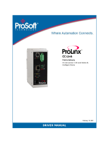
Ex.
The following shows the timing of a data collection by collection at a time interval.
Time interval: 18 milliseconds
: Link scan in which data is collected
: Link scan in which data is not collected
: Link scan time
: Collection interval
Data is collected at 10:24:20.010.
Data is collected at 10: 24: 20.028 - 18 milliseconds later.
Data is collected at 10:24:20.046 - 18 milliseconds later.
Data is collected at 10:24:20.064 - 18 milliseconds later.
Data is collected at 10:24:20.082 - 18 milliseconds later.
■Setting for MI5122-VW
Set the following parameters of MI5122-VW in MI Configurator.
For MI Configurator, refer to the following manual.
MI Configurator Operating Manual
■Data missing
If data collection is not started even after the allowable collection processing delay time (the set collection cycle × 2) elapses,
an exceeded collection cycle is detected and the data for which data collection is not started will be missing.
■Effects of time change
When changing the time of MI5122-VW, collection time interval added to collected data is not fixed but the collection cycle is
fixed.
Item Setting content
Basic Parameter Operation
Related Setting
Time Setting Clock Data
Synchronization
Settings
To Use or Not to
Clock Data
Synchronization
Settings
Select "Enable".
Synchronous
Source
Select "VxWorks part".
Clock Related
Setting
Time Zone Set the same contents as the clock setting in the
Windows part.
Setting to Adjust Clock for Daylight
Saving Time
ÒÓÔÕÖ
22ms22ms22ms 12ms12ms12ms 14ms14ms14ms 24ms24ms24ms
18ms
18ms 18ms 18ms
10:24:20.010 10:24:20.028 10:24:20.046 10:24:20.064 10:24:20.082

4 FUNCTIONS
4.1 Data Collection Function
17
4
Collection for each link scan
This is the method for collecting data of link devices for each link scan.
The features of the data collection for each link scan are as follows:
• Data can be collected for each link scan if the link scan time differs every time.
• Data can be collected in a single link scan without spanning multiple link scans.
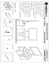
Ex.
The following shows the timing of a data collection by collection for each link scan.
: Link scan in which data is collected
: Link scan time
Data is collected at 10:24:20.010.
Data is collected at 10:24:20.032 - 22 milliseconds later.
Data is collected at 10:24:20.044 - 12 milliseconds later.
Data is collected at 10:24:20.058 - 14 milliseconds later.
Data is collected at 10:24:20.082 - 24 milliseconds later.
■Data missing
Data missing occurs when a data collection is not completed within the set collection cycle. (It is registered as an event.)
■Cyclic transmission cancellation
When MI5122-VW is set as a local station, data is not collected when cyclic transmission is not performed.
Whether cyclic transmission is being performed can be checked according to any of the following methods.
• Check the status of 'D LINK LED' on the front of MI5122-VW.
For details on MI5122-VW, refer to the following manual.
MELIPC MI5000 Series User's Manual (Startup)
• Perform a CC-Link IE Field diagnosis of MI Configurator.
For details on MI Configurator, refer to the following manual.
MI Configurator Operating Manual
ÒÓÔÕ Ö
22ms22ms22ms 12ms12ms12ms 14ms14ms14ms 24ms24ms24ms
10:24:20.010 10:24:20.032 10:24:20.044 10:24:20.058 10:24:20.082

18
4 FUNCTIONS
4.1 Data Collection Function
Collection processing time report
When an enable data collection setting is included in Edgecross Basic Software and the operating status of the software is
changed from RUN to STOP, the maximum and minimum collection processing times when the software was in the RUN state
are reported to the software.
The collection processing time is reported according to the following.
• Unit: Microsecond
• Range: 0 to 4294967295
• When no data is collected while Edgecross Basic Software is in the RUN state, the maximum and minimum
collection processing times are reported as '0'.
• In a report, the unit is changed to millisecond (three decimal places).
Precautions
The operations when collecting the WSTRING type data are as follows:
• For non-surrogate characters, one word is collected from a target device.
• For surrogate characters, two words are collected from a target device.
Ex.
Setting of data to be collected
WSTRING type data [Number of characters = 4] (D0-D7)
Setting of a value to be collected
D0: 'A'
D1: 'B'
D2-D3: ''
D4:'C'
D5:'D'
D6:'E'
D7:'F'
Collection result
"ABC"
indicates a surrogate character.
Page is loading ...
Page is loading ...
Page is loading ...
Page is loading ...
Page is loading ...
Page is loading ...
Page is loading ...
Page is loading ...
Page is loading ...
Page is loading ...
Page is loading ...
Page is loading ...
Page is loading ...
Page is loading ...
Page is loading ...
Page is loading ...
Page is loading ...
Page is loading ...
Page is loading ...
Page is loading ...
Page is loading ...
Page is loading ...
Page is loading ...
Page is loading ...
Page is loading ...
Page is loading ...
Page is loading ...
Page is loading ...
Page is loading ...
Page is loading ...
Page is loading ...
Page is loading ...
Page is loading ...
Page is loading ...
Page is loading ...
Page is loading ...
-
 1
1
-
 2
2
-
 3
3
-
 4
4
-
 5
5
-
 6
6
-
 7
7
-
 8
8
-
 9
9
-
 10
10
-
 11
11
-
 12
12
-
 13
13
-
 14
14
-
 15
15
-
 16
16
-
 17
17
-
 18
18
-
 19
19
-
 20
20
-
 21
21
-
 22
22
-
 23
23
-
 24
24
-
 25
25
-
 26
26
-
 27
27
-
 28
28
-
 29
29
-
 30
30
-
 31
31
-
 32
32
-
 33
33
-
 34
34
-
 35
35
-
 36
36
-
 37
37
-
 38
38
-
 39
39
-
 40
40
-
 41
41
-
 42
42
-
 43
43
-
 44
44
-
 45
45
-
 46
46
-
 47
47
-
 48
48
-
 49
49
-
 50
50
-
 51
51
-
 52
52
-
 53
53
-
 54
54
-
 55
55
-
 56
56


Mitsubishi Electric CC-Link IE Field Network Data Collector (MELIPC MI5122-VW) User manual
- Type
- User manual
Ask a question and I''ll find the answer in the document
Finding information in a document is now easier with AI
Related papers
-
Mitsubishi Electric OPC UA Data Collector User manual
-
-
Mitsubishi Electric MELSEC iQ-R Programming Manual
-
-
-
-
-
-
-
Other documents
-
MasterCool 90066-EX-HOSE User manual
-
XtendLan IPM-401H User manual
-
 Linortek DATA COLLECTOR APP User guide
-
Aiwa MM-RX400 User manual
-
Rosemount TankMaster Net DataCollector User guide
-
Contec DAQ-EC-DIO Reference guide
-
 ProSoft Technology 5209-DFNT-CCLINK Owner's manual
-
 Virtu USA KD-90072-G-WH Installation guide
-
 ProSoft Technology 5209-DFNT-CCLINK Installation guide
-
RKC INSTRUMENT COM-JC User manual


