Moxa EDS-608 Series Quick setup guide

Category
Network switches
Type
Quick setup guide

This manual is also suitable for

P/N: 1802006000016
*1802006000016*
EDS-600 Series
Quick Installation Guide
Moxa EtherDeviceSwitch
Version 5.2, January 2021
Technical Support Contact Information
www.moxa.com/support
Moxa Americas:
Toll
-free: 1-888-669-2872
Tel:
1-714-528-6777
Fax:
1-714-528-6778
Moxa China (Shanghai office):
Toll
-free: 800-820-5036
Tel:
+86-21-5258-9955
Fax:
+86-21-5258-5505
Moxa Europe:
Tel:
+49-89-3 70 03 99-0
Fax:
+49-89-3 70 03 99-99
Moxa Asia-Pacific:
Tel:
+886-2-8919-1230
Fax:
+886-2-8919-1231
Moxa India:
Tel:
+91-80-4172-9088
Fax:
+91-80-4132-1045
2021 Moxa Inc. All rights reserved.
- 2 -
Package Checklist
The Moxa EDS-600 Series is shipped with the following items. If any of
these items is missing or damaged, please contact your customer
service representative for assistance.
1 EDS-600 EtherDevice Switch
RJ45 to DB9 console port cable
Protective caps for unused ports (Only for EDS-611 Series and
EDS-619 Series)
Wall mounting kit (optionalmust be ordered separately)
Anti-vibration wiring kit (optional, must be ordered separately)
Quick installation guide (printed)
Warranty card
Features
Advanced Industrial Networking Capabilities
IPv6 ready (certified by the IPv6 Logo Committee).
IEEE 1588 PTP V2 (Precision Time Protocol) for precise time
synchronization of networks.
Supports LLDP (Link Layer Discovery Protocol)
DHCP Option 82 for IP address assignment with different policies.
Supports Modbus/TCP industrial Ethernet protocol.
Turbo Ring and Turbo Chain (< 20 ms recovery time) and
STP/RSTP.
IGMP snooping and GMRP for filtering multicast traffic.
Port-based VLAN, IEEE 802.1Q VLAN, and GVRP to ease network
planning.
QoS (IEEE 802.1p/1Q) and TOS/DiffServ to increase determinism.
Port Trunking for optimal bandwidth utilization.
IEEE 802.1X, HTTPS, and SSH to enhance network security.
SNMPv1/v2c/v3 for different levels of network management.
RMON for efficient network monitoring and proactive capability.
Bandwidth management prevents unpredictable network status.
Lock port function for blocking unauthorized access based on MAC
address.
Port mirroring allows for online debugging.
Automatic warning by exception through e-mail and relay output.
Digital inputs to integrate sensors and alarms with IP networks.
- 3 -
Panel Views of the EDS-608
Front Panel:
1. System Status LEDs
2. Fast Ethernet Interface Module port LEDs
3. Fast Ethernet Interface Module
4. Terminal block for 2 power inputs, 1 DI/DO, and 1 relay output
5. Grounding screw
6. DIP switches for Ring Master, Ring Coupler, and Turbo Ring
7. RS-232 Console port
8. Screw to attach Fast Ethernet Interface Module
Rear Panel:
9. DIN-Rail Attachment Plate
10. Screw holes for wall mounting kit
- 4 -
Panel Views of the EDS-611
Front Panel:
1. System Status LEDs
2. Fast Ethernet Interface Module port LEDs
3. Fast Ethernet Interface Module
4. Terminal block for 2 power inputs, 1 DI/DO, and 1 Relay output
5. Grounding screw
6. DIP switches for Ring Master, Ring Coupler, and Turbo Ring
7. RS-232 Console port
8. G1 to G3: 10/100/1000 BaseT(X) or 100/1000Base SFP slot
combo ports
9. Screw to attach Fast Ethernet Interface Module
10.
Gigabit Ethernet LEDs
Rear Panel:
11.
DIN-Rail Attachment Plate
12. Screw holes for wall mounting kit
- 5 -
Panel Views of the EDS-616
Front Panel:
1. System Status LEDs
2. Fast Ethernet Interface Module port LEDs
3. Fast Ethernet Interface Module
4. Terminal block for 2 power inputs, 1 DI/DO, and 1 relay output
5. Grounding screw
6. DIP switches for Ring Master, Ring Coupler, and Turbo Ring
7. RS-232 Console port
8. Screw to attach Fast Ethernet Interface Module
Rear
Panel:
9. DIN-Rail Attachment Plate
10. Screw holes for wall mounting kit
- 6 -
Panel Views of the EDS-619
Front
Panel:
1. System Status LEDs
2. Fast Ethernet Interface Module port LEDs
3. Fast Ethernet Interface Module
4. Terminal block for 2 power inputs, 1 DI/DO, and 1 relay output
5. Grounding screw
6. DIP switches for Ring Master, Ring Coupler, and Turbo Ring
7. RS-232 Console port
8. G1 to G3: 10/100/1000 BaseT(X) or 100/1000Base SFP slot
combo ports
9. Screw to attach Fast Ethernet Interface Module
10.
Gigabit Ethernet LEDs
Rear Panel:
11.
DIN-Rail Attachment Plate
12. Screw holes for wall mounting kit
- 7 -
Mounting Dimensions
EDS-608/EDS-611
- 8 -
EDS-616/EDS-619
DIN-Rail Mounting
The aluminum DIN-Rail attachment plate should already be fixed to the
back panel of the EDS-600 when you take it out of the box. If you need
to reattach the DIN-Rail attachment plate to the EDS-600, be sure the
spring-loaded bracket is situated towards the bottom, as shown in the
following figures.
STEP 1:
If the spring
-loaded bracket is
locked in
place, push the recessed
button to release it. Once released,
you should feel some resistance
from the spring as you slide the
bracket up and down a few
millimeters in each direction.
- 9 -
STEP 2:
Insert the top of the DIN
-Rail into
the
top slots on the DIN-Rail
attachment plate.
STEP 3:
The DIN
-Rail attachment unit will
snap into place as shown
in the
following illustration.
To remove the Moxa
EDS-600
switch from the DIN
-Rail, use a
screwdriver
to push down the
spring
-loaded bracket until it locks
in place, as shown in the following
diagram. Next, rotate the bottom of
the switch upwards and then
remove the switch from the DIN
-
Rail.
Wall Mounting (Optional)
For some applications, you will find it convenient to mount the EDS-600
on the wall, as shown in the following illustrations:
STEP 1: Remove the aluminum DIN-Rail attachment plate from the
rear panel of the EDS-600, and then attach the wall mount plates with
M3 screws, as shown in the figure at the right.
EDS-616/EDS-619
STEP 2: Mounting the EDS-600 on the wall requires 4
screws. Use the
EDS-600, with wall mount plates
attached, as a guide to mark the correct locations of
the 4 screws. The heads of the screws should be less
than 6.0 mm in diameter, and the shafts should be
less than 3.5
mm in diameter, as shown in the figure
at the right.
- 10 -
NOTE
Before tightening the screws into the wall, make sure the screw
head and shank size are suitable by inserting the screw through
one of the keyhole
-shaped apertures of the Wall Mounting
Plates.
Do not screw the screws in all the wayleave about 2 mm to allow
room for sliding the wall mount panel between the wall and the screws.
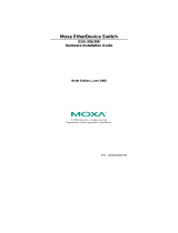
STEP 3: Once the screws are fixed to the wall, insert the four screw
heads through the wide parts of the keyhole-shaped apertures, and
then slide the EDS-600 downwards, as indicated in the figure at the
right. Tighten the four screws for more stability.
ATEX Information
1. Certificate number: DEMKO 11 ATEX 1007817X
2. Certification string: Ex nA nC IIC T4 Gc
3. Standards covered: EN 60079-0:2012+A11:2013, EN 60079-
15:2010
4. Special Conditions of Use:
Devices are to be installed in an ATEX certified Zone 2
enclosure rated IP54 in accordance with EN 60529 that is
accessible only with the use of a tool.
Devices are for use in an area of not more than pollution
degree 2 in accordance with EN 60664-1.
Provisions shall be made, external to the apparatus, to
prevent the rated voltage being exceeded by the transient
disturbances of more than 140%.
Accessory Modules CM-600-4TX, CM-600-4MSC, CM-600-
4SSC, CM-600-4MST, CM-600-2MSC/2TX, CM-600-2SSC/2TX,
CM-600-3MSC/1TX, CM-600-3SSC/1TX must be used with
Models EDS-608, EDS-608-T, EDS-611, EDS-611-T, EDS-616,
EDS-616-T, EDS-619, and EDS-619-T.
When customers use their own optical SFP communication
modules, these must be limited to Laser Class 1 only in
accordance with EN 60825-1.
- 11 -
Wiring Requirements
WARNING
Do not disconnect modules or wires unless power has been
switched off or the area is known to be non
-hazardous. The
devices may only be connected to the supply voltage shown on
the type plate. The devices are designed for operation with a
S
afety Extra-Low V
oltage. Thus, they may only be connected to
the supply voltage connections and to the signal contact with
the
Safety Extra-Low Voltages (SELV) in compliance with
IEC950/ EN60950-1/ VDE0805.
ATTENTION
These devices are open
-type devices that need to be installed
in an enclosure only ac
cessible with the use of a tool that is
suitable for the environment.
ATTENTION
Safety First!
Be sure to disconnect the power cord before installing and/or
wiring your Moxa EtherDevice Switch.
Calculate the maximum possible current in each power wire and
commo
n wire. Observe all electrical codes dictating the
maximum current allowable for each wire size.
If the current goes above the maximum ratings, the wiring
could overheat, causing serious damage to your equipment.
Please read and follow these guidelines:
Use separate paths to route wiring for power and devices. If power
wiring and device wiring paths must cross, make sure the wires are
perpendicular at the intersection point.
NOTE: Do not run signal or communications wiring and power
wiring through the same wire conduit. To avoid interference, wires
with different signal characteristics should be routed separately.
You can use the type of signal transmitted through a wire to
determine which wires should be kept separate. The rule of thumb
is that wiring sharing similar electrical characteristics can be
bundled together
You should separate input wiring from output wiring
We advise that you label the wiring to all devices in the system.
Grounding the Moxa EDS-600
EDS switches are designed to enhance EMS performance by grounding.
EDS switches come with metal DIN-Rail brackets for grounding the
switches. For optimal EMS performance, connect the chassis ground nut
on the switch to the grounding point.
- 12 -
ATTENTION
This product
is intended to be mounted to a well-grounded
mounting surface such as a metal panel.
Wiring the Relay Contact
The EDS-600 has a set of relay outputs. The relay contact uses two of
the terminal block’s contacts located on the EDS-600’s front panel.
Refer to the next section for detailed instructions on how to connect the
wires to the terminal block connector, and how to attach the terminal
block connector to the terminal block receptor.
In this section, we illustrate the meaning of the two contacts used to
connect the relay contact.
FAULT:
The relay contacts of the 6
-pin
terminal block connector are used
to detect user
-configured events.
The
three wires attached to the
f
ault contacts form an open circuit
when a user
-configured event is
triggered. If a user
-configured
event does not occur, the
fault
circuit remains closed.
The relay
output has current carrying
capacity of 1 A @ 24 VDC.
Relay Circuit Status when Power is On/Off
Power On
COM & NC
Open Circuit
COM & NO
Short Circuit
Power Off
COM & NC
Short Circuit
COM & NO
Open Circuit
Wiring the Redundant Power Inputs
The EDS-600 has two sets of power inputs, power 1 and power 2,
which are located on the EDS-600’s front panel. Power 1 is the bottom
- 13 -
two contacts on the upper 6-contact terminal block and power 2 is the
top two contacts on the lower 5-contact terminal block.
STEP 1
: Insert the
negative/positive DC wires into the
V
-/V+ terminals, respectively.
STEP 2: To keep the DC wires from
pulling loose, use a small flat
-
blade
screwdriver to tighten the wire
-
clamp screws on the front of the
terminal block connector.
STEP 3
: Insert the plastic terminal
block connector prongs into the
terminal block receptor, which is
located on
the EDS-600’s front
panel.
ATTENTION
We suggest using a copper conductor with the cable type
AWG
(American
Wire Gauge) 22 and the corresponding pin type
cable terminals. In addition, the wire must be able to withstand
at least 105°C.
Wiring the Digital Inputs
The EDS-600 has one set of digital inputs (DIs). Each DI consists of two
contacts of the 5-pin terminal block connector on the EDS-600’s front
panel, which are used for the one DC input. The top and front views of
one of the terminal block connectors are shown here.
+13 to +30 V for state “1”
-30 to +3 V for state “0”
Max. input current: 8 mA
STEP 1: Insert the negative
(ground)/positive DI wires into the
/I1 terminals, respectively.
STEP 2
: To keep the DI wires from
pulling loose, use a small flat
-blade
screwdriver to tighten the wire
-
clamp screws on the front of the
terminal block connector
.
STEP 3
: Insert the plastic terminal
block connector prongs into the
terminal block receptor, which is
located on
the EDS-600’s front
panel.
Communication Connections
EDS-600 Series switches have different types of communication ports:
1 RJ45 console port (RS-232 interface).
Up to 3 Gigabit combo 10/100/1000T(X) or 100/1000BaseSFP
ports.
4-port Fast Ethernet interface modules that include
10/100BaseT(X) and 100BaseFX ports with SC/ST connectors.
- 14 -
RS-232 Connection
The EDS-600 has one RS-232 (10-pin RJ45) console port, located on
the front panel. Use either an RJ45-to-DB9 (see the following cable
wiring diagrams) to connect the EDS-600’s console port to your PC’s
COM port. You may then use a console terminal program, such as Moxa
PComm Terminal Emulator, to access the EDS-600’s console
configuration utility.
RJ45 (10-pin) Console Port Pinouts
Pin
Description
1
2
DSR
3
RTS
4
5
TxD
6
RxD
7
GND
8
CTS
9
DTR
10
RJ45 (10-pin) to DB9 (F) Cable Wiring
10/100/1000BaseT(X) Ethernet Port Connection
The 10/100/1000BaseT(X) ports located on switch’s front panel are
used to connect to Ethernet-enabled devices. Most users will choose to
configure these ports for Auto MDI/MDI-X mode, in which case the
port’s pinouts are adjusted automatically depending on the type of
Ethernet cable used (straight-through or cross-over), and the type of
device (NIC-type or HUB/Switch-type) connected to the port.
The following charts display the pinouts for both MDI (NIC-type) ports
and MDI-X (HUB/Switch-type) ports. We also present cable wiring
diagrams for straight-through and cross-over Ethernet cables.
- 15 -
10/100Base T(x) RJ45 Pinouts
MDI Port Pinouts
MDI-X Port Pinouts
8-pin RJ45
Pin
Signal
1
Tx+
2
Tx-
3
Rx+
6
Rx-
Pin
Signal
1
Rx+
2
Rx-
3
Tx+
6
Tx-
1000BaseT RJ45 Pinouts
Pin
MDI
MDI-X
1
BI_DA+
BI_DB+
2
BI_DA-
BI_DB-
3
BI_DB+
BI_DA+
4
BI_DC+
BI_DD+
5
BI_DC-
BI_DD-
6
BI_DB-
BI_DA-
7
BI_DD+
BI_DC+
8
BI_DD-
BI_DC-
RJ45 (8-pin) to RJ45 (8-pin) Straight-Through Cable Wiring
RJ45 (8-pin) to RJ45 (8-pin) Cross-Over Cable Wiring
100BaseFX or 1000BaseSFP Fiber Port
The Gigabit Ethernet ports on the EDS-600 series are SFP slots, which
require 100BaseFX SFP or Gigabit mini-GBIC fiber transceivers to work
properly. Moxa provides complete transceiver models for various
distance requirements.
- 16 -
The concept behind the LC port and cable is quite straightforward.
Suppose you are connecting devices 1 and 2. Unlike electrical signals,
optical signals do not require a circuit in order to transmit data.
Consequently, one of the optical lines is used to transmit data from
device 1 to device 2, and the other optical line is used to transmit data
from device 2 to device 1, for full-duplex transmission.
Remember to connect the Tx (transmit) port of device 1 to the Rx
(receive) port of device 2, and the Rx (receive) port of device 1 to the
Tx (transmit) port of device 2. If you make your own cable, we suggest
labeling the two sides of the same line with the same letter (A-to-A and
B-to-B, as shown below, or A1-to-A2 and B1-to-B2).
LC-Port Pinouts
LC-Port to LC-Port Cable Wiring
ATTENTION
This is a Class 1 Laser/LED product. To avoid causing serious
damage to your eyes, do not stare directly into the laser beam.
Turbo Ring DIP Switch Settings
EDS-600 series switches are managed redundant plug-and-play
Ethernet switches. The proprietary Turbo Ring protocol was developed
by Moxa to provide better network reliability and faster recovery time.
Moxa Turbo Ring’s recovery time is less than 300 ms (Turbo Ring) or
20 ms (Turbo Ring V2) compared to a 3- to 5-minute recovery time
for commercial switchesdecreasing the possible loss caused by
network failures in an industrial setting.
Four DIP switches are located on the top panel of the EDS-600 to allow
users to set up Turbo Ring easily within seconds. If you do not want to
use a hardware DIP switch to set up Turbo Ring, you can use a web
browser, Telnet, or console to disable this function.
NOTE
Refer to the Turbo Ring DIP Switch section and Using
Communication Redundancy
section in the User’s Manual for
detailed information about the settings and usage of
Turbo
Ring and Turbo Ring V2.
EDS-600 Series DIP Switches
The default setting for each DIP
Switch is OFF.
The
following table explains the effect of setting
the DIP Switch to the ON position
.
- 17 -
Turbo RingDIP Switch Settings
DIP 1
DIP 2
DIP 3
DIP 4
Reserved for
future use.
ON: Enables this
EDS as the Ring
Master.
ON: Enables the
default “Ring
Coupling” ports.
ON: Activates
DIP switches 1,
2, 3 to configure
“Turbo Ring”
settings.
OFF: This EDS
will not be the
Ring Master.
OFF: Do not use
this EDS as the
ring coupler.
OFF: DIP
switches 1, 2, 3
will be disabled.
Turbo Ring V2DIP Switch Settings
DIP 1
DIP 2
DIP 3
DIP 4
ON: Enables the
default “Ring
Coupling
(backup)port.
ON: Enables this
EDS as the Ring
Master.
ON: Enables the
default “Ring
Coupling” port.
ON: Activates
DIP switches 1,
2, 3 to configure
“Turbo Ring V2
settings.
OFF: Enables the
default “Ring
Coupling
(primary)port.
OFF: This EDS
will not be the
Ring Master.
OFF: Do not use
this EDS as a
ring coupler.
OFF: DIP
switches 1, 2, 3
will be disabled.
NOTE
You must enable the Turbo Ring function first before using the
DIP switch to activate the Master and Coupler functions.
NOTE
If you do not enable any of the EDS-600 switches to be the
Ring Master, the Turbo Ring protocol will automatically choose
the EDS
-600 with the smallest MAC address range to be the
Ring Master. If you accidentally enable more than one EDS
-
600
to be the Ring
Master, these EDS-600 switches will auto-
negotiate to determine which one will be the Ring Master.
Bypass Relay Function (For CM-600-4TX-BP)
The CM-600-4TX-BP is equipped with a bypass relay function that
includes 2 pairs: port 1 and port 2 are one pair, port 3 and port 4 are
the other pair. When the switch is operating normally, the bypass
module works in the same way as the other ports. That is, frame
ingressions are processed and then forwarded. In the event the switch
stops working due to a power failure, the bypass relay function will be
triggered to ensure non-stop data communication.
The figure below illustrates the bypass relay function. For example, if
Switch B loses power, then the pair will be bypassed through the relay
circuit and the transmission line from Switch A to B and the
transmission line from Switch B to C will interconnect automatically and
immediately. Therefore, by implementing this function, there will be no
stoppage. The bypass relay function helps the network recover from
single-node failures in a linear topology.
- 18 -
Since the maximum length of a category 5 twisted-pair cable is 100
meters, the cable length must be considered when designing a network
that utilizes this function. For example, the total length of the cables
from Switch A to C, or B to C must be no more than 100 meters. This
way, if the two adjacent nodes (Switch B or C for example) encounter a
power failure, there will be no stoppage, provided that the total length
of the cables A-to-C, and B-to-D does not exceed 100 meters.
The bypass relay function works best for networks with linear
topologies. The bypass relay function is not recommended to be used in
ring topologies because network loops may occur when redundancy
protocols such as RSTP or TurboRingare applied.
LED Indicators
The front panel of the EDS-600 contains several LED indicators. The
function of each LED is described in the following table:
LED
Color
State
Description
Main System
PWR1 AMBER
On
Power is being supplied to power input
PWR1.
Off
Power is not being supplied to power
input PWR1.
PWR2 AMBER
On
Power is being supplied to power input
PWR2.
Off
Power is not being supplied to power
input PWR2.
FAULT RED
On
When the corresponding PORT alarm
is enabled, and a user-configured
event is triggered.
Off
When the corresponding PORT alarm
is enabled and a user-configured
event is not triggered, or when the
corresponding PORT alarm is disabled.
MSTR/
HEAD
GREEN
On
When the EDS-600 is set as the
Master of the Turbo Ring or is set as
the Head of the Turbo Chain.
Blinking
When the EDS-600 is set as the Ring
Master of the Turbo Ring or as the
Head of the Turbo Chain and the
Turbo Ring or Turbo Chain is down.
CPLR/
TAIL
GREEN
On
When the EDS-600 coupling function
is enabled to form a back-
up path or if
it is set as the Tail of the Turbo Chain.
Blinking
When the Turbo Chain is down.
Off
To disable the EDS-600’s coupling
function.
- 19 -
LED
Color
State
Description
G1/G2/G3
(EDS-611/
EDS-619
only)
AMBER
On
10/100 Mbps link is active.
Blinking
Data is being transmitted at 10/100
Mbps.
Off
10/100 Mbps link is inactive.
GREEN
On
1000 Mbps link is active.
Blinking
Data is being transmitted at 1000
Mbps.
Off
1000 Mbps link is inactive.
Interface Module
10/100M
AMBER
On
10 Mbps link is active.
Blinking
Data is being transmitted at 10 Mbps.
Off
10 Mbps link is inactive.
Green
On
100 Mbps link is active.
Blinking
Data is being transmitted at 100
Mbps.
Off
100 Mbps link is inactive.
Specifications
Technology
Standards
IEEE802.3, 802.3u, 802.3x, 802.1D, 802.1w,
802.1Q, 802.1p, 802.1X, 802.3ad, 802.3z
Protocols
IGMP V1/V2 device, GMRP, GVRP, SNMP
V1/V2c/V3, DHCP Server/Client, BootP, TFTP,
DHCP Option66.67.82, SSH, MODBUS/TCP,
SNMP INFORM, SNTP, SMTP, RARP, RMON
MSTR/HEAD, CPLR/TAIL, 10/100/1000M (GB
port), 10/100M (Module TX/FX port), IEEE
1588 PTP, and IPv6
MIB MIB-II, Ethernet-like MIB, P-BRIDGE MIB, Q-
BRIDGE MIB, Bridge MIB, RSTP MIB, RMON
MIB Group 1,2,3,9
Interface
RJ45 Ports
10/100/1000BaseT(X) auto negotiation speed,
F/H duplex mode, and auto MDI/MDI-X
connection
Fiber Ports
Optional 100/1000Base SFP modules
Console Port
RS-232 (10-pin RJ45)
System LED Indicators
PWR1, PWR2, FAULT, MSTR/HEAD, CPLR/TAIL,
G1, G2, G3
Module LED Indicators
10/100M for TP port, 100M for Fiber port
Alarm Contact
Two relay outputs with current carrying
capacity of 1 A @ 24 VDC
Digital Input
Two inputs with the same ground, but
electrically isolated from the electronics
• For state “1”: +13 to +30 V
• For state “0”: -30 to +3 V
• Max. input current: 8 mA
Power
Input Voltage
12/24/48 VDC, redundant inputs
Input Current (@12 V) EDS-608: 2.3 A
EDS-611: 2.3 A
EDS-616: 2.3 A
- 20 -
EDS-619: 2.3 A
Connection
Two removable 5-pin and 6-pin terminal blocks
Overload Current
Protection
Present
Reverse Polarity
Protection
Present
Mechanical
Casing
IP30 protection, metal case
Dimensions (W × H ×
D)
EDS-608/611:
125 x 151 x 157.4 mm
(4.92 x 5.95 x 6.20 in)
EDS-616/619:
185 x 151 x 157.4 mm
(7.28 x 5.95 x 6.20 in)
Weight
EDS-608: 1.95 kg
EDS-611: 2.02 kg
EDS-616: 2.45 kg
EDS-619: 2.51 kg
Installation
DIN-rail, wall mounting kit (optional kit), anti-
vibration wiring kit (optional)
Environment
Operating Temperature
0 to 60°C (32 to 140°F), standard models
-40 to 75°C (-40 to 167°F) for -T models
Storage Temperature
-40 to 85°C (-40 to 185°F)
Ambient Relative
Humidity
5 to 95% (non-condensing)
Regulatory Approvals
Safety
UL 508, EN62368-1
Hazardous Location UL/cUL Class I, Division 2, Groups A, B, C, and
D; ATEX Zone 2, Ex nC nL IIC T4
EMI
FCC Part 15B Class A, CISPR 32 Class A,
EN 55032 Class A, EN 61000-6-4
EMS
EN61000-6-2
EN61000-4-2 (ESD),
level 2 for multi-mode models with
ST connectors
level 3 for all other models
EN61000-4-3 (RS), Level 3
EN61000-4-4 (EFT), Level 4
EN61000-4-5 (Surge), Level 3
EN61000-4-6 (CS), Level 3
EN61000-4-8
Maritime
DNV, GL, ABS, LR, NK
Rail Traffic
EN50121-4
Shock
IEC60068-2-27
Free Fall
IEC60068-2-32
Vibration
IEC60068-2-6
Traffic Control
NEMA TS2
WARRANTY
5 years
  • Page 1 1
  • Page 2 2
  • Page 3 3
  • Page 4 4
  • Page 5 5
  • Page 6 6
  • Page 7 7
  • Page 8 8
  • Page 9 9
  • Page 10 10
  • Page 11 11
  • Page 12 12
  • Page 13 13
  • Page 14 14
  • Page 15 15
  • Page 16 16
  • Page 17 17
  • Page 18 18
  • Page 19 19
  • Page 20 20

Moxa EDS-608 Series Quick setup guide

Category
Network switches
Type
Quick setup guide
This manual is also suitable for

Ask a question and I''ll find the answer in the document

Finding information in a document is now easier with AI