Lithonia Lighting 5G1MB LED 30K 90CRI M6 User manual
- Type
- User manual

• To reduce the risk of death, personal injury or property damage from fi re, electric
shock, falling parts, cuts/abrasions, and other hazards please read all warnings and
instructions included with and on the fi xture box and all fi xture labels.
• Before installing, servicing, or performing routine maintenance upon this equipment,
follow these general precautions.
• Installation and service of luminaires should be performed by a qualifi ed licensed
electrician.
• Maintenance of the luminaires should be performed by person(s) familiar with the
luminaires’ construction and operation and any hazards involved. Regular fi xture
maintenance programs are recommended.
• It will occasionally be necessary to clean the outside of the refractor/lens. Frequency
of cleaning will depend on ambient dirt level and minimum light output which is
acceptable to user. Refractor/lens should be washed in a solution of warm water and
any mild, non-abrasive household detergent, rinsed with clean water and wiped dry.
Should optical assembly become dirty on the inside, wipe refractor/lens and clean in
above manner, replacing damaged gaskets as necessary.
• DO NOT INSTALL DAMAGED PRODUCT! This luminaire has been properly
packed so that no parts should have been damaged during transit. Inspect to confi rm.
Any part damaged or broken during or after assembly should be replaced.
• Recycle: For information on how to recycle LED electronic products, please
visit www.epa.gov.
• These instructions do not purport to cover all details or variations in equipment nor to
provide every possible contingency to meet in connection with installation, operation,
or maintenance. Should further information be desired or should particular problems
arise which are not covered suffi ciently for the purchaser’s or owner’s purposes, this
matter should be referred to Acuity Brands Lighting, Inc.
READ AND FOLLOW ALL SAFETY INSTRUCTIONS! SAVE THESE
INSTRUCTIONS AND DELIVER TO OWNER AFTER INSTALLATION
WARNING RISK OF ELECTRIC SHOCK
CAUTION RISK OF INJURY
WARNING RISK OF BURN
CAUTION RISK OF FIRE
• Disconnect or turn off power before installation or servicing.
• Verify that supply voltage is correct by comparing it with the luminaire
label information.
• Make all electrical and grounded connections in accordance with the National
Electrical Code (NEC) and any applicable local code requirements.
• All wiring connections should be capped with UL approved recognized
wire connectors.
• Wear gloves and safety glasses at all times when removing luminaire from carton,
installing, servicing or performing maintenance.
• Avoid direct eye exposure to the light source while it is on.
• Allow lamp/fi xture to cool before handling. Do not touch enclosure or light source.
• Do not exceed maximum wattage marked on luminaire label.
• Follow all manufacturer’s warnings, recommendations and restrictions for: driver
type, burning position, mounting locations/methods, replacement and recycling.
• Keep combustible and other materials that can burn, away from lamp/lens.
• Do not operate in close proximity to persons, combustible materials or substances
affected by heat or drying.
LED IMPORTANT SAFETY INSTRUCTIONS
CAUTION: RISK OF PRODUCT DAMAGE
• Never connect components under load.
• Do not mount or support these fi xtures in a manner that can cut the outer jacket or
damage wire insulation.
• Never connect an LED product to an unapproved dimmer pack. Contact ABL
directly for any dimmers not specifi cally recommended for the product.
• Unless individual product specifi cations deem otherwise: Allow for some volume of
airspace around fi xture. Avoid covering LED fi xtures with insulation, foam, or other
material that will prevent convection or conduction cooling.
• Unless individual product specifi cations deem otherwise: Maximum ambient
temperature is 90°C. Do not operate fi xture at temperatures higher than this.
• Unless individual product specifi cations deem otherwise: Never mount in places
where fi xture will be exposed to rain, high humidity, extreme temperature changes
or restricted ventilation.
• LED products are Polarity Sensitive. Ensure proper Polarity before installation.
• Electrostatic Discharge (ESD): ESD can damage LED fi xtures. Personal grounding
equipment must be worn during all installation or servicing of the unit.
• Do not touch individual electrical components as this can cause ESD, shorten lamp
life, or alter performance.
• There are no user serviceable parts inside the unit. Do not rewire, reconfi gure,
or modify the unit or attempt any repairs yourself. Additionally, fi eld replacement
of the LED assembly or lamps is not allowed by UL standards at this time. In the
unlikely event your unit may require service, stop using the unit immediately and
contact an ABL representative.
All luminaires that contain electronic devices that generate frequencies above 9kHz from
any component within the luminaire comply with one of the following Part 15 of the FCC
Rules. Operation is subject to the following two conditions:
(1) This device may not cause harmful interference
(2) This device must accept any interference received, including interference
that may cause undesired operation.
This device complies with Part 18 of the FCC Rules but may cause interference with
cordless and cell phones, radios, televisions, and other electronic devices. To correct
the problem move the device away from the luminaire or plug into a different outlet.
This product may cause interference to radio equipment and should not be installed near
maritime safety communications equipment or other critical navigation or communica-
tions equipment operating between 0.45-30MHz.
Failure to follow any of these instructions could void product warranties.
For a complete listing of product Terms and Conditions, please visit
www.acuitybrands.com.
OUR BRANDS
Indoor/Outdoor: Lithonia Lighting, Carandini, Holophane, RELOC
Indoor Lighting: Gotham, Mark Architectural Lighting, Peerless, Renaissance
Lighting, Winona Lighting
Outdoor Lighting: American Electric Lighting, Antique Street Lamps, Hydrel, Tersen
Controls: DARK TO LIGHT, Lighting Control & Design, ROAM, Sensor Switch,
Synergy
Acuity Brands Lighting, Inc. assumes no responsibility for claims arising out of
improper or careless installation or handling of its products.
ABL LED General Warnings, Form No. 503.203
© 2010 Acuity Brands Lighting, Inc. All rights reserved. 12/01/10

LithoniaDownlighting PartNo.CJ5201106Rev.A
OneLithoniaWay/Conyers,GA30012
©20011 Acuity Brands Lighting, Inc., 4/13
800‐315‐4935/www.lithonia.com Page2of15
INSTALLATIONINSTRUCTIONS
4”‐4BL,4G1BaffleandGimbalLEDModules
5”‐5BL,5G1BaffleandGimbalLEDModules
6
” ‐
6BL, 6G1 Baffle and Gimbal LED Modules
WARNING: Prior to installing the fixture, disconnect ALL power supplies to the unit. To prevent wiring damage or abrasions, do
not expose wiring to edges of sheet metal or other sharp objects. This module may be installed into TYPE IC or NON-IC
installations. For TYPE NON-IC INSTALLATION ONLY: No insulation may be placed over the top of or within 3” (76mm)
of the fixture.
The retrofit kits is accepted as a component of a luminaire where the suitability of the combination shall be determined by
CSA or authorities have jurisdiction. The contents of the retrofit kits are:
LED Module
Socket Adaptor
Two Red Splice Connectors
Instruction Sheet
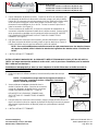
WARNING: RISK OF FIRE OR ELECTRICAL SHOCK.
Install this kit only in the luminaires that has the construction
features and dimensions shown in the photographs or drawings.
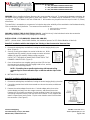
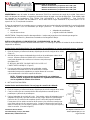
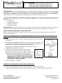
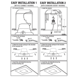
INSTALLATION – 4” LED MODULES (Model# 4BL AND 4G1)
(NOTE – pictures show L Series Baffle modules, but installation process for LED Gimbal Modules is identical)
Retrofit 4” Installation with Socket Adaptor into Existing or New Construction Recessed Can
:
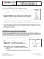
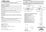
1. Remove the existing lamp and reflector, leaving the socket hanging freely by the
wires.
(Figure 1)
2. Securely screw socket adapter into socket inside the can. While
supporting the LED module, plug the orange connector of socket
adapter into the LED module’s mating orange connector.
DO NOT LET THE MODULE HANG UNSUPPORTED BY THE
ORANGE CONNECTORS. (Figure 2)
3. Once all connections are complete, gently push the LED trim into
the recessed can opening until clips engage inside of can, and the
trim is flush with the ceiling surface.
NOTE: If installing into a retrofit-style housing with internal ceiling
support clips, be sure to offset the clips on the trim with the clips inside
can.
4. INSTALLATION COMPLETE.
Retrofit 4” Installation with Hardwire Connection Kit
:
1. Remove the existing lamp and reflector, leaving the socket hanging freely by the wires
2. Cut existing socket wires inside the recessed can close to the socket, and discard
the socket.
3. Remove the socket adapter from the box. Cut both adapter wires close to the
socket adapter and away from the orange connector, and discard the socket.
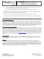
Remove the (2) red splice-connectors from the hardwire kit bag. Pair the housing
and orange connector wires by color into each red connector. Firmly squeeze the
metal U-shaped insert into the wires. Flip the cover closed to secure and insulate
the connection. (See Figure 3)
Figure 2
Figure 3
Figure 1

LithoniaDownlighting PartNo.CJ5201106Rev.A
OneLithoniaWay/Conyers,GA30012
©20011 Acuity Brands Lighting, Inc., 4/13
800‐315‐4935/www.lithonia.com Page3of15
INSTALLATIONINSTRUCTIONS
4”‐4BL,4G1BaffleandGimbalLEDModules
5”‐5BL,5G1BaffleandGimbalLEDModules
6
” ‐
6BL, 6G1 Baffle and Gimbal LED Modules
4. While supporting the LED module, plug connector from the module into the mating connector just installed into the
recessed can. Push the wires and mated connectors up into the recessed can. DO NOT LET THE MODULE HANG
UNSUPPORTED BY THE ORANGE CONNECTORS. (See Figure 2)
5. Once all connections are complete, gently push the LED trim into the recessed can opening until clips engage inside
of can, and the trim is flush with the ceiling surface.
NOTE: If installing into a remodeler-style recessed can with internal ceiling support clips, be sure to
offset the trim clips away from the black clips inside can.
6. INSTALLATION COMPLETE.
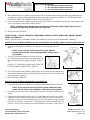
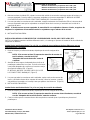
INSTALLATION – 6” AND 5” LED BAFFLE AND GIMBAL MODULES (BAFFLE MODEL# 6BL AND 5BL; GIMBAL
MODEL# 6G1 AND 5G1)
(NOTE - pictures show L Series Baffle modules, but installation process for LED Gimbal Modules is identical.)
Retrofit 5” and 6” Installation with Edison Base Socket Adaptor into Existing or New Construction Recessed Can
:
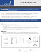
1. Remove the existing lamp and reflector, leaving the socket hanging freely by the
wires.
NOTE: If your can does not have (2) torsion spring retention
brackets inside, see the “Torsion Spring Adapter” section prior to
going further.
2. Securely screw socket adapter into socket inside the
can. Plug the orange connector of socket adapter into
the LED module’s mating orange connector. (Figure
4)
DO NOT LET THE MODULE HANG UNSUPPORTED
BY THE ORANGE CONNECTORS. (Figure 5)
3. Once all connections are complete, squeeze each pair of torsion springs together and
seat inside of brackets in fixture. Release springs, and gently push trim into fixture until
flush with ceiling. (Figure 6)
4. INSTALLATION COMPLETE.
Retrofit 5” and 6” Installation with Hardwire Connection Kit
:
1. Remove the existing lamp and reflector, leaving the socket hanging freely by the wires.
NOTE: If your can does not have (2) torsion spring retention brackets
inside, see the “Torsion Spring Adapter” section prior to going further.
2. Cut existing socket wires inside the recessed can close to the socket, and discard the
socket.
3. Remove the socket adapter from the box. Cut both adapter wires close to the socket
adapter and away from the orange connector, and discard the socket. Remove the (2)
red splice-connectors from the hardwire kit bag. Pair the housing and orange connector
wires by color into each red connector. Firmly squeeze the metal U-shaped insert into
the wires. Flip the cover closed to secure and insulate the connection. (See Figure 7)
Fi
g
ure 4
Figure 5
Figure 6
Fi
g
ure 7

LithoniaDownlighting PartNo.CJ5201106Rev.A
OneLithoniaWay/Conyers,GA30012
©20011 Acuity Brands Lighting, Inc., 4/13
800‐315‐4935/www.lithonia.com Page4of15
INSTALLATIONINSTRUCTIONS
4”‐4BL,4G1BaffleandGimbalLEDModules
5”‐5BL,5G1BaffleandGimbalLEDModules
6
” ‐
6BL, 6G1 Baffle and Gimbal LED Modules
4. Plug orange connector from the module into the mating orange connector just installed into the recessed can. Push
the wires and mated connectors up into the recessed can. DO NOT LET THE MODULE HANG UNSUPPORTED BY
THE ORANGE CONNECTORS. (See Figure 5)
5. Once all connections are complete, squeeze each pair of torsion springs together and place into brackets inside
fixture. Releases springs, and gently push trim into fixture until flush with ceiling. (See Figure 6)
6. INSTALLATION COMPLETE.
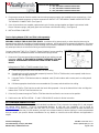
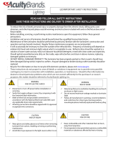
Torsion Spring Adapter (TSA5 and TSA6 sold separately)
:
WARNING - RISK OF FIRE OR ELECTRIC SHOCK
. Luminaires wiring, power supply, or other electrical parts may be
damaged when drilling for installation of retrofit assembly hardware. Inspect wiring and components for damage. Only those
open holes indicated in the photographs and/or drawings may be made or altered as a result of kit installation. Do not leave
any other open holes in an enclosure of wiring or electrical components.
You may require the TSA5 (5”) or TSA6 (6”) (Figure 8) option if you are retrofitting
an old-style can or a remodeler that does not have torsion spring brackets.
1. Remove the (3) screws around the perimeter inside of your existing can and
keep them.
NOTE: IF THRE ARE NO SCREWS TO REMOVE, YOU WILL
HAVE TO TEMPORARILY REMOVE CAN FROM CEILING TO DRILL
HOLES
.
Drilling Holes for TSA5 or TSA6 (Remodeler-Style Cans)
1a. Unlock ceiling clips and remove remodeler can from ceiling.
1b. Supporting the can while suspended, temporarily insert the TSA5 or TSA6 bracket, hooks upward, inside the can
and flush with the edge of the can.
1c. Using the TSA5 or TSA6 bracket-slots as a template, mark (3) hole locations with a center punch or writing utensil
inside can.
1d. Drill three appropriate sized holes to accommodate the (3) screws, and reinstall can into ceiling.
2. Reinsert the TSA5 or TSA6 into the can with the hooks facing upward. Line up the slots with the holes and align the
bottom of the TSA5 or TSA6 flush with the can.
3. Drive the (3) screws through the TSA5 or TSA6 bracket-slots and into the can to secure into position.
4. Refer back to the “INSTALLATION – 5” and 6” LED MODULE” section for further instruction.
RECOMMENDED DIMMING SWITCHES
The Lithonia LED Modules are compatible with standard incandescent (Triac), electronic low voltage (ELV), and magnetic
low voltage (MLV) dimmers. A list of recommended dimmers, to help with your installation, can be found on
www.lithonia.com
by searching for 4BL, 5BL, 6BL, 4G1, 5G1, or 6G1. Exclusion from the list does not mean a dimmer will
not work in conjunction with our LED modules, just that it has not been tested by Lithonia Lighting. It is also recommended
that you contact your specific dimmer manufacturer for any details or concerns since each dimmer and application is
unique.
Figure 8

LithoniaDownlighting PartNo.CJ5201106Rev.A
OneLithoniaWay/Conyers,GA30012
©20011 Acuity Brands Lighting, Inc., 4/13
800‐315‐4935/www.lithonia.com Page5of15
INSTALLATIONINSTRUCTIONS
4”‐4BL,4G1BaffleandGimbalLEDModules
5”‐5BL,5G1BaffleandGimbalLEDModules
6
” ‐
6BL, 6G1 Baffle and Gimbal LED Modules
RECESSED CAN COMPATIBILITY
Lithonia's LED modules were tested to fit in a minimum enclosure of 4.0” diameter by 4.90” height, while having a
maximum diameter (for flange coverage) of 4.125”, for the 4" LED module and 5.35” diameter by 5.31” height, while
having a maximum diameter (for flange coverage) of 6.25”, for the 5" LED module. 6” LED modules are tested to fit in a
minimum enclosure of 6.0” diameter by 5.75” height, with a maximum flange diameter of 7.5”. This was selected to
provide fitment into most industry housings available. For our complete (but not exhaustive) competitive housing
compatibility list, please go to www.lithonialighting.com
and search for 4BL, 5BL, 6BL, 4G1, 5G1, or 6G1.
LISTINGS
CSA certified to US and Canadian safety standards; Energy Star qualified; California Title 24 compliant; damp location
listed; and WSEC ASTEM E283 for Air-Tight rated with IC housings.
WARRANTY
Lithonia Lighting warrants LED products sold hereunder to be free from defect in manufacturing, under normal and proper
storage, installation, and use, for a period of five (5) years from the date of shipment. Our guarantee liability extends only
to the repair or replacement of the defective part, and no labor charges for correction of the defect by repair or
replacement will be paid by Lithonia Lighting unless prior written authority has been granted by contacting our Post Sale
department at 1-800-315-4935.
Page is loading ...
Page is loading ...
Page is loading ...
Page is loading ...
Page is loading ...
Page is loading ...
Page is loading ...
Page is loading ...
Page is loading ...
Page is loading ...
-
 1
1
-
 2
2
-
 3
3
-
 4
4
-
 5
5
-
 6
6
-
 7
7
-
 8
8
-
 9
9
-
 10
10
-
 11
11
-
 12
12
-
 13
13
-
 14
14
-
 15
15


Lithonia Lighting 5G1MB LED 30K 90CRI M6 User manual
- Type
- User manual
Ask a question and I''ll find the answer in the document
Finding information in a document is now easier with AI
in other languages
Related papers
-
Lithonia Lighting SBL LED Installation guide
-
-
-
 Acuity Brands Lighting Lithonia Lighting CSXW LED Installation guide
-
Acuity Brands IBZ Installation guide
-
-
Acuity Brands WF6 Downlight Installation guide
-
-
Lithonia Lighting TWX3LEDALO50KMVOLT Installation guide
-

Other documents
-
Faro 75563 Operating instructions
-
 Feit Electric LEDRSQ6/930 Installation guide
-
 Feit Electric LEDRSQ4/930/4 Installation guide
-
 Maxxima MRL-61900NW-A Installation guide
-
Super Bright LEDS SMDJ2-KIT User manual
-
 Hyperikon HyperEDL56-30 Installation guide
-
Juno JKWT4RD06LM30K90B4 Installation guide
-
AcuityBrands Legacy DSX1 User manual
-
 Generation Lighting 1153AT Installation guide
-
 Acuity Brands Lighting Lithonia Lighting HLA LED Quick start guide


