Page is loading ...

WARNING:
If the information in these instructions are not followed exactly,
a fi re or explosion may result causing property damage,
personal injury or loss of life.
FOR YOUR SAFETY
Do not store or use gasoline or other fl ammable vapors and
liquids in the vicinity of this or any other appliance.
Installation and service must be performed by a qualifi ed
installer, service agency or the gas supplier.
FOR YOUR SAFETY
What to do if you smell gas:
Do not try to light any appliance
Do not touch any electrical switch:
do not use any phone in your
building.
Immediately call your gas supplier
from a neighbour's phone. Follow
the gas supplier's instructions.
If you cannot reach your gas
supplier, call the fi re department.
FPI FIREPLACE PRODUCTS INTERNATIONAL LTD. 6988 Venture St., Delta, BC Canada, V4G 1H4
918-920a
03/13/14
Owners &
Installation Manual
Tested by:
Installer: Please complete the details on the back cover
and leave this manual with the homeowner.
Homeowner: Please keep these instructions for future reference.
MODELS: B41XTE-NG1
B41XTE-LP1
www.regency-fi re.com
Regency Bellavista
™
B41XTE
Gas Fireplace

2
Regency Bellavista™ B41XTE-1 Gas Fireplace
To the New Owner:
Congratulations!
You are the owner of a state-of-the-art Gas Fireplace by REGENCY
®
. The Bellavista™
B41XTE has been designed to provide you with all the warmth and charm of a wood fi replace
at the fl ick of a switch. The Bellavista™ B41XTE has been approved by Warnock Hersey/
Intertek for both safety and effi ciency. As it also bears our own mark, it promises to provide
you with economy, comfort and security for many trouble free years to follow. Please take
a moment now to acquaint yourself with these instructions and the many features of your
Regency
®
Fireplace.

Regency Bellavista™ B41XTE -1 Gas Fireplace
3
MANUFACTURED MOBILE HOME REQUIREMENTS
INFORMATION FOR MOBILE/MANUFACTURED HOMES AFTER FIRST SALE
This Regency
®
product has been tested and listed by Warnock Hersey as a Direct Vent Wall Furnace to the following standards:
VENTED GAS FIREPLACE HEATERS ANSI Z21.88-2009 / CSA 2.33-2009 and GAS-FIRED APPLIANCES FOR USE AT HIGH
ALTITUDES CAN / CGA 2.17-M91.
This Direct Vent System Appliance must be installed in accordance with the manufacturer's installation instructions and the Manufactured
Home Construction and Safety Standard, Title 24 CFR, Part 3280, or the current Standard of Fire Safety Criteria for Manufactured
Home Installations, Sites, and Communities ANSI/NFPA 501A, and with CAN/CSA Z240-MH Mobile Home Standard in Canada.
This appliance installation must comply with the manufacturer's installation instructions and local codes, if any. In the absence of local
codes follow the current National Fuel Gas Code, ANSI Z223.1 and the current National Electrical Code ANSI/NFPA 70 in the U.S.A.,
and the current CAN/CGA B149 Gas Installation Code and the current Canadian Electrical Code CSA C22.1 in Canada.
This appliance comes equipped with a dedicated #8 Ground Lug for attachment of the ground wire to the steel chassis as applicable
to local codes.
The appliance, when installed, must be electrically grounded in accordance with local codes or, in the absence of local codes, with
the National Electrical Code, ANSI/NFPA 70, or the Canadian Electrical Code, CSA C22.1.
This appliance may only be installed in an aftermarket permanently located, manufactured (U.S.A only) or mobile home, where not
prohibited by local codes.
This appliance can only be used with the type of gas indicated on the rating plate. This appliance is not convertible for use with other
gases.
Ensure that structural members are not cut or weakened during installation.

4
Regency Bellavista™ B41XTE-1 Gas Fireplace
TABLE OF CONTENTS
SAFETY LABEL
Copy of Safety Decal .....................................................5
REQUIREMENTS
MA Code - CO Detector.................................................6
DIMENSIONS
Unit Dimensions ............................................................7
INSTALLATION
Important Message ......................................................8
Before You Start ............................................................8
General Safety Information............................................8
Installation Checklist .....................................................9
Locating Your Gas Fireplace .........................................9
Clearances ..................................................................10
Mantel Clearances.......................................................11
Mantel Leg Clearances................................................12
Non-Combustible Requirements .................................12
Framing ......................................................................13
Finishing ......................................................................14
Unit Assembly Prior to Installation ...............................15
Top Standoff Assembly ........................................15
Top Facing Support ..............................................15
Side Nailing Strips ...............................................15
Venting Introduction .....................................................18
Vent Restrictor & Baffl e Installation .............................18
Exterior Vent Termination Requirements .....................19
5" x 8" RigiD Pipe ......................................................20
Venting Arrangements for horizontal terminations ..
22
Flex Vent or RIGID PIPE 5" x 8" ..........................22
Rear Venting Defl ector Installation ......................22
For rear vented horizontal terminations ...............22
Horizontal Terminations ...............................................23
Flex Vent 5" x 8" .................................................23
RIGID PIPE 5" x 8" ..............................................24
AstroCap XL & Rigid REAR VENT KIT ........................25
Venting arrangementsfor Horizontal Terminations .......26
Rigid Pipe Venting Systems ........................................27
Basic Horizontal & Vertical Terminations .............27
Horizontal terminations ................................................28
Two (2) 90
o
Elbows (Rigid Pipe 5" x 8") ...............28
Horizontal terminations ................................................28
Vertical terminations ...................................................30
Three (3) 90
o
Elbows (Rigid Pipe 5" x 8") ............30
Unit Installation with Horizontal Termination ...............31
Unit Installation with Horizontal Termination ...............32
Unit installation with Vertical Termination ....................33
Gas Line Installation ....................................................33
Pilot Adjustment ...........................................................34
High Elevation .............................................................34
886 S.I.T. Valve Description .........................................34
Gas Pipe Pressure Testing ..........................................34
Brick panel installation .................................................35
Optional panel installation ...........................................36
Log set installation .......................................................38
Optional Fan installation ..............................................42
Optional Wall Thermostat ...........................................44
Optional Remote Control .............................................44
Optional Wall Switch ....................................................44
GT Remote installation ................................................46
GTM Remote installation .............................................47
GTMF Remote installation ...........................................49
Wiring Diagram ............................................................51
Profl ame system wiring diagram .................................52
Profl ame system wiring diagram .................................52
Confi guration: 886 GTMF ............................................52
Optional accent light Installation ..................................53
Flush glass door Installation ........................................55
Optional fi nishing trim Installation ................................55
Full Screen Arch Door and Frame Installation .............57
OPERATING INSTRUCTIONS
Operating Instructions .................................................60
Lighting Procedure ......................................................60
Shutdown Procedure ...................................................60
First Fire ......................................................................60
Normal Operating Sounds of Gas Appliances .............60
Aeration Adjustment ....................................................60
Copy of Lighting Plate Instructions ..............................61
MAINTENANCE
Maintenance Instructions.............................................62
Log Replacement ........................................................62
Door Glass...................................................................62
Accent Light Bulb Replacement ..................................63
Valve Replacement ......................................................64
Installing Valve .............................................................64
PARTS LIST
Main Assembly ............................................................65
Burner Assembly .........................................................66
Accessories .................................................................67
WARRANTY
The Warranty: Limited Lifetime ...................................71

Regency Bellavista™ B41XTE -1 Gas Fireplace
5
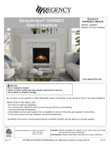
SAFETY LABEL
This is a copy of the label that accompanies each
Bellavista™ B41XTE Direct Vent Gas Fireplace.
We have printed a copy of the contents here
for your review.
NOTE: Regency
®
units are constantly being
improved. Check the label on the unit and if
there is a difference, the label on the unit is
the correct one.
For the State of Massachusetts, installation
and repair must be done by a plumber or
gas fi tter licensed in the Commonwealth of
Massachusetts.
For the State of Massachusetts, fl exible
connectors shall not exceed 36 inches in
length.
For the State of Massachusetts, the appli-
ances individual manual shut-off must be a
t-handle type valve.
The State of Massachusetts requires the
installation of a carbon monoxide alarm in
accordance with NFPA 720 and a CO alarm
with battery back up in the same room where
the gas appliance is installed.
DO NOT REMOVE THIS LABEL / NE PAS ENLEVER CETTE ÉTIQUETTE
369
369
DOOR SEAL: Please
check that the door is
properly sealed
Minimum Clearances to Combustibles /
Degagement Minimum De Materiaux Combustibles
Serial No./ No de serie
MAY BE INSTALLED IN MANUFACTURED (MOBILE) HOMES AFTER FIRST SALE.
Listed: VENTED GAS FIREPLACE HEATER
Certified for/Certifi e pour: CANADA and U.S.A.
Tested to:
é
CAN/CGA-2.17-M91(R2009)
ANSI Z21.88-2009/CSA 2.33-2009
Duplicate S/N
(See Instruction Manual for
detailed instructions)
ÉÉ
é
QUIP A L'UISINE POUR GAZ PROPANE
CONCU POUR ETRE POELE: Mod le B41XTE-LP1
PROPANE GAS: Model B41XTE-LP1
Minimum supply pressure
Manifold pressure high
Manifold pressure low
Orifice size
Minimum input
Maximum input
Altitude
NATURAL GAS: Model B41XTE-NG1
APPAREIL FONCTIONNANT AU NATURAL GAS
CONCU POUR ETRE POELE: Mod le B41XTE-NG1
Pression d'allimentation minimum
Pression à la tubulure d' chappement lev e
Pression à la tubulure d' chappement basse
Grandeur de l'injecteur
D bit Calorifique minimum selon
D bit Calorifique maximum selon
l'altitude
é
ééé
é
é
é
5.0" (1.25 kPa)
3.5" WC/C.E. (0.87 kPa)
1.6" WC/C.E. (0.40 kPa)
# 3 0 DMS
30,000 Btu/h (8.79 kW)
42,500 Btu/h (12.45 kW)
0-4500 ft/pi (0-1372 m)
WC/C.E.
P t # 918 921
Pression d'allimentation minimum
Pression à la tubulure d' chappement lev e
Pression à la tubulure d' chappement basse
Grandeur de l'injecteur
D bit Calorifique minimum selon
D bit Calorifique maximum selon
l'altitude
ééé
é
é
é
11" (2.74 kPa)
10" WC/C.E. (2..49 kPa)
6.4" WC/C.E. (1.60 kPa)
# 4 9 DMS
29,500 Btu/h (8.65 kW)
37,500 Btu/h (10.99 kW)
0-4500 ft/pi (0-1372 m)
WC/C.E.
Minimum supply pressure
Manifold pressure high
Manifold pressure low
Orifice size
Minimum input
Maximum input
Altitude
E
B
A
C
D
F
FPI Fireplace Products International Ltd.
Delta, BC, Canada
918-921a
This appliance must be installed in accordance with local codes, if any; if none, follow the National Fuel Gas Code, ANSI Z223.1, or Natural Gas and Propane Installation Code, CSA B149.1.
This appliance must be installed in accordance with the Standard CAN/CSA Z240 MH, Mobile Housing, in Canada, or with the Manufactured Home Construction and Safety Standard, Title 24 CFR, Part 3280, in the
United States, or when such a standard is not applicable, ANSI/NCSBCS A225.1/NFPA 501A, Manufactured Home Installations Standard.
This appliance is only for use with the type of gas indicated on the rating plate and may be installed in an aftermarket, permanently located, manufactured (mobile) home where not prohibited by local codes. See
owner's manual for details.
Installer l'appareil selon les codes ou règlements locaux, ou, en l'absence de tels règlements, selon les codes d'installation ANSI Z223.1, National Fuel Gas Code ou CSA-B149.1 en vigueur.
Installer l'appareil selon la norme CAN/CSA-Z240, Série MM, Maison mobiles ou CAN/CSA-Z240 VC, Véhicules de camping, ou la norme 24 CFR Part 3280, Manufactured Home Construction and Safety Standard.
Si ces normes ne sont pas pertinentes, utilisez la norme ANSI/NCSBCS A225.1/NFPA 501A, Manufactured Home Installations Standard, ou ANSI A119.2 ou NFPA 501C Standard for Recreational Vehicles.
This vented gas fireplace heater is not for use with air filters. Ne pas utiliser de filtre à air avec ce foyer au gaz à évacuation.
For use with glass doors certified with the appliance only
Made in Canada/ Fabrique au Canada
Cet appareil doit être utilize uniquement avec le type de gaz indiqué sur la plaque signalétique. Cet appareil peut être installé dans une maison préfabriquée ou mobile (É.-U. seulement) installée à demeure si les
règlements locaux le permettent. Voir la notice de l'utilisateur pour plus de renseignements. Cet appareil ne peut pas être utilisé avec d'autres gaz sauf si une trousse de conversion certifiée est fournie.
Pour utilisation uniquement avec les portes en verre certifiées avec l'appareil
Electrical supply / Électrique 115VAC, 1.13 A, 60Hz.
VENTED GAS FIREPLACE HEATER - NOT FOR USE WITH SOLID FUELS.
NE PAS UTILISER AVEC DU COMBUSTIBLE SOLIDE. FOYER AU GAZ À ÉVACUATION -
Mantel Clearances from
Fireplace Opening:
(A) Min. 15" (381mm)
Side Wall Clearance
from Fireplace Opening
B) Min. 9” (229mm)
Ceiling from Top of
Fireplace Opening:
C) 33-3/4” (857mm)
Mantel Depth:
D) Max. 12” (304mm)
Alcove Clearances:
E) Min. Width 60" (1524mm),
F) Max. Depth 36" (914mm)
Minimum Vent Clearances:
Horizontal Top 3" (76mm)
Horizontal Side 2" (51mm)
Horizontal Bottom 2" (51mm)
Vertical Vent 2" (51mm)
4001172

6
Regency Bellavista™ B41XTE-1 Gas Fireplace
REQUIREMENTS
5.08: Modifications to NFPA-54, Chapter 10
(2) Revise 10.8.3 by adding the following additional requirements:
(a) For all side wall horizontally vented gas fueled equipment installed in every dwelling, building or structure used in whole or in part for
residential purposes, including those owned or operated by the Commonwealth and where the side wall exhaust vent termination is less than
seven (7) feet above finished grade in the area of the venting, including but not limited to decks and porches, the following requirements shall
be satisfied:
1. INSTALLATION OF CARBON MONOXIDE DETECTORS. At the time of installation of the side wall horizontal vented gas fueled
equipment, the installing plumber or gasfitter shall observe that a hard wired carbon monoxide detector with an alarm and battery back-up is
installed on the floor level where the gas equipment is to be installed. In addition, the installing plumber or gasfitter shall observe that a battery
operated or hard wired carbon monoxide detector with an alarm is installed on each additional level of the dwelling, building or structure
served by the side wall horizontal vented gas fueled equipment. It shall be the responsibility of the property owner to secure the services of
qualified licensed professionals for the installation of hard wired carbon monoxide detectors
a. In the event that the side wall horizontally vented gas fueled equipment is installed in a crawl space or an attic, the hard wired carbon
monoxide detector with alarm and battery back-up may be installed on the next adjacent floor level.
b. In the event that the requirements of this subdivision can not be met at the time of completion of installation, the owner shall have a period of
thirty (30) days to comply with the above requirements; provided, however, that during said thirty (30) day period, a battery operated carbon
monoxide detector with an alarm shall be installed.
2. APPROVED CARBON MONOXIDE DETECTORS. Each carbon monoxide detector as required in accordance with the above provisions
shall comply with NFPA 720 and be ANSI/UL 2034 listed and IAS certified.
3. SIGNAGE. A metal or plastic identification plate shall be permanently mounted to the exterior of the building at a minimum height of eight
(8) feet above grade directly in line with the exhaust vent terminal for the horizontally vented gas fueled heating appliance or equipment. The
sign shall read, in print size no less than one-half (1/2) inch in size, "GAS VENT DIRECTLY BELOW. KEEP CLEAR OF ALL
OBSTRUCTIONS".
4. INSPECTION. The state or local gas inspector of the side wall horizontally vented gas fueled equipment shall not approve the installation
unless, upon inspection, the inspector observes carbon monoxide detectors and signage installed in accordance with the provisions of 248 CMR
5.08(2)(a)1 through 4.
(b) EXEMPTIONS: The following equipment is exempt from 248 CMR 5.08(2)(a)1 through 4:
1. The equipment listed in Chapter 10 entitled "Equipment Not Required To Be Vented" in the most current edition of NFPA 54 as adopted by
the Board; and
2. Product Approved side wall horizontally vented gas fueled equipment installed in a room or structure separate from the dwelling, building or
structure used in whole or in part for residential purposes.
(c) MANUFACTURER REQUIREMENTS - GAS EQUIPMENT VENTING SYSTEM PROVIDED. When the manufacturer of Product
Approved side wall horizontally vented gas equipment provides a venting system design or venting system components with the equipment, the
instructions provided by the manufacturer for installation of the equipment and the venting system shall include:
1. Detailed instructions for the installation of the venting system design or the venting system components; and
2. A complete parts list for the venting system design or venting system.
(d) MANUFACTURER REQUIREMENTS - GAS EQUIPMENT VENTING SYSTEM NOT PROVIDED. When the manufacturer of a
Product Approved side wall horizontally vented gas fueled equipment does not provide the parts for venting the flue gases, but identifies
"special venting systems", the following requirements shall be satisfied by the manufacturer:
1. The referenced "special venting system" instructions shall be included with the appliance or equipment installation instructions; and
2. The "special venting systems" shall be Product Approved by the Board, and the instructions for that system shall include a parts list and
detailed installation instructions.
(e) A copy of all installation instructions for all Product Approved side wall horizontally vented gas fueled equipment, all venting instructions,
all parts lists for venting instructions, and/or all venting design instructions shall remain with the appliance or equipment at the completion of
the installation.
MA Code - CO Detector
(for the State of Massachusetts only)

Regency Bellavista™ B41XTE -1 Gas Fireplace
7
DIMENSIONS
UNIT DIMENSIONS
46-11/16” (1186mm)
38-3/16” (970mm)
41-11/16” (1059mm)
43” (1092mm)
35” (889mm)
49-3/16” (1249mm)
41-5/8” (1057mm)
36-11/16” (932mm)
38-7/8” (987mm)
24” (610mm)
36-3/8” (924mm)
22-5/16” (567mm)
19-7/16” (494mm)
1”
(25mm)
23-1/4” (591mm)
13-3/16” (335mm)
28-1/2” (724mm)
38-1/2” (978mm)

8
Regency Bellavista™ B41XTE-1 Gas Fireplace
INSTALLATION
10) Be aware of electrical wiring locations in
walls and ceilings when cutting holes for
termination.
11) Under no circumstances should this appliance
be modifi ed. Parts that have to be removed
for servicing should be replaced prior to
operating this appliance.
12) Installation and any repairs to this appliance
should be done by a qualifi ed service person.
A professional service person should be called
to inspect this appliance annually. Make it a
practice to have all of your gas appliances
checked annually.
13) Do not slam shut or strike the glass door.
14) Under no circumstances should any solid
fuels (wood, paper, cardboard, coal, etc.) be
used in this appliance.
15) The appliance area must be kept clear and
free of combustible materials, (gases and
other fl ammable vapours and liquids).
Emissions from burning wood or gas could
contain chemicals known to the State of
California to cause cancer, birth defects or
other reproductive harm.
IMPORTANT MESSAGE
SAVE THESE
INSTRUCTIONS
The B41XTE Gas Fireplace must be installed
in accordance with these instructions. Carefully
read all the instructions in this manual fi rst.
Consult the "authority having jurisdiction" to
determine the need for a permit prior to starting
the installation. It is the responsibility of the
installer to ensure this fi replace is installed in
compliance with manufacturers instructions and
all applicable codes.
BEFORE YOU START
Safe installation and operation of this appliance
requires common sense, however, we are
required by the Canadian Safety Standards
and ANSI Standards to make you aware of
the following:
GENERAL SAFETY
INFORMATION
1) The appliance installation must conform
with local codes or, in the absence of local
codes, with the current Canadian or National
Gas Codes, CAN1-B149 or ANSI Z223.1
Installation Codes.
2) The appliance when installed, must be
electrically grounded in accordance with local
codes, or in the absence of local codes with
the current National Electrical Code, ANSI/
NFPA 70 or CSA C22.1 Canadian Electrical
Code.
3) See general construction and assembly
instructions. The appliance and vent should
be enclosed.
4) This appliance must be connected to the
specifi ed vent and termination cap to the
outside of the building envelope. Never vent
to another room or inside a building. Make
sure that the vent is fi tted as per Venting
instructions.
5) Inspect the venting system annually for
blockage and any signs of deterioration.
6) Venting terminals shall not be recessed into
a wall or siding.
7) Any safety glass removed for servicing must
be replaced prior to operating the appliance.
8) To prevent injury, do not allow anyone who
is unfamiliar with the operation to use the
fi replace.
9) Wear gloves and safety glasses for protection
while doing required maintenance.
CLOTHING OR OTHER FLAMMABLE
MATERIAL SHOULD NOT BE PLACED
ON OR NEAR THE APPLIANCE.
CHILDREN AND ADULTS SHOULD BE
ALERTED TO THE HAZARDS OF HIGH
SURFACE TEMPERATURES, ESPE-
CIALLY THE FIREPLACE GLASS, AND
SHOULD STAY AWAY TO AVOID BURNS
OR CLOTHING IGNITION.
INSTALLATION AND REPAIR SHOULD
BE DONE BY AN AUTHORIZED
SERVICE PERSON. THE APPLIANCE
SHOULD BE INSPECTED BEFORE
USE AND AT LEAST ANNUALLY BY A
PROFESSIONAL SERVICE PERSON.
MORE FREQUENT CLEANING MAY
BE REQUIRED DUE TO EXCESSIVE
LINT FROM CARPETING, BEDDING
MATERIAL, ETC. IT IS IMPERATIVE THAT
CONTROL COMPARTMENTS, BURNERS
AND CIRCULATING AIR PASSAGEWAYS
OF THE APPLIANCE BE KEPT CLEAN.
DUE TO HIGH TEMPERATURES, THE
APPLIANCE SHOULD BE LOCATED
OUT OF TRAFFIC AND AWAY FROM
FURNITURE AND DRAPERIES.
WARNING: FAILURE TO INSTALL THIS
APPLIANCE CORRECTLY WILL VOID
YOUR WARRANTY AND MAY CAUSE A
SERIOUS HOUSE FIRE.
YOUNG CHILDREN SHOULD BE CARE-
FULLY SUPERVISED WHEN THEY ARE
IN THE SAME AREA AS THE APPLI-
ANCE. TODDLERS, YOUNG CHILDREN
AND OTHERS MAY BE SUSCEPTIBLE
TO ACCIDENTAL CONTACT BURNS. A
PHYSICAL BARRIERS IS RECOMMEND-
ED IF THERE ARE AT RISK INDIVIDUAL
IN THE HOUSE. TO RESTRICT ACCESS
TO A FIREPLACE OR STOVE, INSTALL
AN ADJUSTABLE SAFETY GATE TO
KEEP TODDLERS, YOUNG CHILDREN
AND OTHER AT RISK INDIVIDUALS OUT
OF THE ROOM AND AWAY FROM HOT
SURFACES.

Regency Bellavista™ B41XTE -1 Gas Fireplace
9
INSTALLATION
This includes:
1) Clocking the appliance to ensure the correct
fi ring rate (rate noted on label), after burning
appliance for 15 minutes.
2) If required, adjusting the primary air to ensure
that the fl ame does not carbon. First allow
the unit to burn for 15-20 min. to stabilize.
CAUTION: Any alteration to the product that
causes sooting or carboning that results
in damage is not the responsibility of the
manufacturer.
LOCATING YOUR
GAS FIREPLACE
A) Flat on Wall
B) Flat on Wall Corner
C) Recessed into Wall/Alcove
D) Corner
Diagram 1
1) When selecting a location for your fi replace,
ensure that the clearances are met.
2) The appliance must be installed on a fl at,
solid, continuous surface For example a
wood, metal or concrete fl oor or in a raised (on
the wall) application. The appliance must be
installed on a metal or wood panel extending
the full width and depth of the appliance.
3) The B41XTE Gas Fireplace can be installed
in a recessed position or framed out into the
room as in A, B, C and D. See Diagram 1.
INSTALLATION
CHECKLIST
1) Locate appliance
a) Room location (Refer to "Locating Your
Gas fi replace" section)
b) Clearances to Combustibles (Refer to
"Clearances" section)
c) Mantle Clearances (Refer to "Combustible
Mantel Clearances" section)
d) Framing & Finishing Requirements (Refer
to "Framing & Finishing" section)
e) Venting Requirements (Refer to "Venting"
section)
2) Assemble Top Standoffs and Top Facing
Support and Side Nailing Strips (Refer to
"Unit Assembly Prior to Installation" Section).
Note: Must be done before installing unit into
place.
3) Install vent (Refer to "Venting" sections).
4) Make gas connections. Test the pilot. Must be
as per diagram (Refer to "Pilot Adjustment"
section).
5) Make electrical connections to receptacle
supplied with unit (recommended).
6) Install standard and optional features. Refer
to the following sections:
a. Install 4AA batteries into battery pack
b. Inner Panels or Brick Panels (Required)
c. Log Set Installation
d. Standard Flush Door
e. Remote Control
f. Wall Switch
g. Wall Thermostat
h. Fan Installation (Optional)
i. Light Installation (Optional)
j. Louvers / Flush Panels
k. Full Screen Arch Door
l. Finishing Trim (Optional)
7) Final check.
4) This appliance is Listed for bedroom
installations using the standard Remote
(millivolt thermostat system). Some areas
may have further requirements, check local
codes before installation.
5) The B41XTE Gas Fireplace are approved
for alcove installations, see "Clearances"
section for details.
6) We recommend that you plan your installation
on paper using exact measurements for
clearances and floor protection before
actually installing this appliance. Have an
authorized inspector, dealer, or installer
review your plans before installation.
Note: For vent terminations refer to
"Exterior Vent Termination Locations"
section.

10
Regency Bellavista™ B41XTE-1 Gas Fireplace
INSTALLATION
Caution Requirements
The top, back and sides of the fi replace are defi ned by
standoffs. The metal ends of the standoff may NOT be
recessed into combustible construction.
WARNING
Fire hazard is an extreme risk
if these clearances (air space) to combustible materials are not
adhered to. It is of greatest importance that this fi replace and vent
system be installed only in accordance with these instructions.
CLEARANCES
The clearances listed below are Minimum distances unless otherwise stated:
A major cause of chimney related fi res is failure to maintain required clearances (air space) to combustible materials. It is of the greatest
importance that this fi replace and vent system be installed only in accordance with these instructions.
E
B
C
D
F
A
B41XTE Clearance Requirements
Minimum Vent Clearances
to Combustibles
Horizontal Top 3" (76mm)
Horizontal Side 2 " (51mm)
Horizontal Bottom 2" (51mm)
Vertical Vent 2" (51mm)
E
F
Alcove
NOTE: A 16" deep non-combustible hearth pad is
recommended for hardwood fl ooring and carpet.
Clearance: Dimension Measured From:
A: Mantel Height (min.) 15" (381mm) Top of Fireplace Opening
B: Sidewall 9" (229mm) Side of Fireplace Opening
C: Ceiling 33-3/4" (933mm) Top of Fireplace Opening
D: Mantel Depth (max.) 12" (304mm) 23-1/4" (591mm)
from Top of Fireplace Opening
E: Alcove Width 60" (1524mm) Wall to Wall (Minimum)
F: Alcove Depth 36" (914mm) Front to Back Wall (Maximum)
Notes: 0" No Hearth Required

Regency Bellavista™ B41XTE -1 Gas Fireplace
11
INSTALLATION
MANTEL CLEARANCES
Note: Ensure the paint that is used on the mantel and the facing is "heat resistant" or the paint may discolour.
Due to the extreme heat this fi replace emits, the mantel clearances are critical. Combustible mantel clearances from top of front facing are
shown in the diagram on the right.
Note: A non-combustible mantel may be installed at a lower height if the framing is made of metal studs covered with a non-combustible
board.
Mantel Clearances
B41XT
ABCD
From Top of
Fireplace Opening
35-1/4"
(895mm)
23-1/4"
(591mm)
19-1/2"
(495mm)
15"
(381mm)
Combustible
0
Top of
Fireplace
Opening
12”
1"
7”
A
B
C
Non-combustible
Header
(steel stud)
on edge
To Floor
2
0
12
6
4
810
14
D
Side View
13-1/2”
Non-combustible
Standoff

12
Regency Bellavista™ B41XTE-1 Gas Fireplace
INSTALLATION
MANTEL LEG CLEARANCES
NON-COMBUSTIBLE REQUIREMENTS
Min. 13-1/2"
(343mm)
50-1/4"
(1276mm)
Non-combustible
Min. 3-1/2”
(89mm)
48-3/4"
(1238mm)
Non-combustible
41-3/4"
(1060mm)
Non-combustible
Material
Non-combustible
Header
(steel stud)
on edge
47-1/4" (1200mm)
Framing
36-3/4"
(933mm)
Min. 3-1/2”
(89mm)
Non-combustible
Non-combustible
9” Side Wall
(Measured from side of
Fireplace Opening)
7”
4”
Mantel leg
Mantel leg
Allowable mantel leg
projection.
3"
1-1/2"

Regency Bellavista™ B41XTE -1 Gas Fireplace
13
INSTALLATION
FRAMING
M
N
O
Q
P
R
U
V
T
Opening for gas
connection
11" (279mm)
dia. Hole through
wall Vent.
Non-Combustible
Header
(steel stud) on edge
Drywall, Wood
(or other facing)
W
Non-Combustible Facing
Rear Vent
Top Vent
S
S
Non-Combustible
Header
(steel stud)
on edge
Framing Dimensions Description B41XTE
M Framing Width 47-1/4"(1200mm)
N Framing Height 49-1/2" (1257mm)
O (Rear Vent) Framing Depth - Rear Vent 23-1/4" (591mm)
O (Top Vent) Framing Depth - Top Vent 22-5/8" (575mm)
P Corner Facing Wall Width 60-1/4" (1530mm)
Q Corner Facing Wall Width 85-3/16" (2163mm)
R (Rear Vent) Framed Chase Ceiling - Rear 49-1/2" (1257mm)
R (Top Vent) Framed Chase Ceiling - Top 54-1/2" (1384mm)
S (Rear Vent) Vent Centerline Height - Rear 28-1/2" (724mm)
S (Top Vent) Vent Centerline Height - Top 47-1/2" (1207mm) Rigid / Flex
T Gas Connection Height 1-1/2" (38mm)
U Gas Connection Inset 5" (127mm)
V Gas Connection Width 3-1/4" (82mm)
W Non-Combustible Top Height 13-1/2" (343mm)
** Important: Framing height requires consideration of the hearth depth. Dimension N = N + the thickness of the installed hearth.

14
Regency Bellavista™ B41XTE-1 Gas Fireplace
INSTALLATION
FINISHING
Non-combustible
Material
J-style Trim
or metal corner bead
may be used to finish these
edges
Non-combustible
Material
Non-combustible
Material
Diagram 2
Diagram 1
IMPORTANT FINISHING DETAIL NOTE:
Before placing unit into fi nal position - it is important to know the total
thickness / height of fi nished hearth (tile, carpet, etc.) The base of the
fi replace should be level or higher than the fi nished hearth height.
Diagram 3: Shown with optional Finishing Trim
Finishing material -
thicker than 1-1/4"
Important:
Finishing materials such as tile, river rock, etc, must not protrude beyond
the front facing fl anges the sides and top of the fi rebox opening.
Full Screen Doors Only:
If fi nishing with any material thicker than 1-1/4" - a 3/4" gap must be
maintained between the full screen doors and the fi nishing material.
This gap is necessary to facilitate the installation and removal of the full
screen doors.
Note:
All non-combustible facing material should butt up cleanly to the fl anges
around the fi rebox opening.
Rough edges will be visible from the front view with the fl ush louvers or
fl ush panels - if not using the optional fi nishing trim.
To maintain a clean fi nished edge - it is recommended to install the non-
combustible facing material with the fi nished edge against the fi replace
/ nailing strips.
Alternatively, you can use J Style Trim or Metal Corner Bead to cover
cut edges of the non-combustible facing material.
Diagram 5
Diagram 4
Full Screen
Door
3/4"
43
3
8
"
37
5
8
"

Regency Bellavista™ B41XTE -1 Gas Fireplace
15
INSTALLATION
UNIT ASSEMBLY PRIOR TO INSTALLATION
BEFORE YOU START
The Top Facing Support, the Side Nailing Strips, the 2 Top Standoffs and the Flue Collar must be correctly positioned and attached before the fi replace
is moved into position.
TOP STANDOFF ASSEMBLY
The top standoffs are shipped in a fl at position and must be folded into shape and attached.
1) Remove the standoffs from the fi replace top.
2) Take each standoff and bend into the correct shape. Bend up at the bend lines until
the screw holes in the standoff and the pre-punched screw holes on the fi replace
top line up.
3) Attach the standoff securely to the top with 2 screws per standoff (on opposite
corners).
TOP FACING SUPPORT
Determine the total thickness of facing material (e.g. drywall or wood plus ceramic tiles) to
allow the fi nished surface to be fl ush with the front of the unit. Total facing thickness can vary
from 1/2" (13mm) to 1-1/4" (32mm) thick.
The Top Facing Support can be mounted in
3 different positions depending on the
thickness of the facing material.
1) Mount Top Facing Support using the 3 supplied screws into the three pre-punched screw
holes on the top front of the unit. Use hole positions A, B, or C depending on your facing depth.
Screw Facing Material
Position Depth
A 1/2" / 13mm
B 7/8" / 22mm
C* 1-1/4" / 32mm
* For "C" screw position the top facing
support is reversed.
Top Facing Support
A
B
C
Screw holes for
Top Facing
Support
Top Facing Support
is reversed
for “C” hole position
A
B
C
"C" Screw Position:
For a facing material depth of 1-1/4" (32mm),
the top facing support must be reversed.
Top Facing
Support
SIDE NAILING STRIPS
The side nailing strips come attached to the unit.
There are 2 plates, one on the top and bottom
that can be folded out as required depending on
the facing depth as per chart shown.
Facing Material
Depth
1/2" / 13mm
7/8" / 22mm
1-1/4" / 32mm

16
Regency Bellavista™ B41XTE-1 Gas Fireplace
INSTALLATION
CONVERSION TO TOP VENT
Note: This conversion must be done prior to the unit being placed in position.
The unit comes equipped as a rear vent unit. These instructions are to be used, only if the unit is going to be top vented.
Top Collar Assembly Kit Includes:
1 Intake Collar Assembly with Gasket
1 Intake Cover Plate with Gasket
1 Top/Rear Exhaust Assembly with Gasket
1 Baffl e Plate
29 1/4" x 1/2" Screws (4 spares)
1 Restrictor
1 Intake Collar Gasket (spare)
1 Exhaust Assembly Gasket (spare)
1 Insulation Plate Cover
1 Insulation Filling
1) Remove the door by releasing the spring hooks at the bottom and lifting
the door up off the door frame.
2) From inside the fi rebox, remove the baffl e plate by removing 4 screws
- remove top front screw fi rst.
Baffl e Plate
3) From the inside of the fi rebox, remove the exhaust assembly by remov-
ing the 10 screws.
7) From the outside top of the fi rebox - remove the intake cover plate by
removing the 4 - 1/4" x 1/2 " screws.
5) From the outside top of the fi rebox - remove top insulation cover plate
- by removing 2 screws as shown and discard.
4) From the outside rear of the fi rebox, remove the intake collar assembly.
Remove the 4 - 1/4" x 1/2" screws.
Exhaust
Assembly
Intake Collar
Assembly
Before proceeding to Step 8, inspect condition of all gaskets.
DO NOT install parts with damaged gaskets. Replace if necessary with
spare gaskets supplied.
Flush
Door
Swing door out
from the bottom
and lift up off
of door frame
6) From the outside top of the fi rebox - slide the square piece of insulation
out and discard.

Regency Bellavista™ B41XTE -1 Gas Fireplace
17
INSTALLATION
10) From the inside of the fi rebox, place the exhaust assembly into position
as shown in Diagram 1 and secure with 10 - 1/4" x 1/2" screws (Diagram
2). Ensure all screws are tight, but do not over tighten.
All 10 screws must be used.
Diagram 1
Diagram 2
12) From the outside rear of the fi rebox, install the intake cover plate with
4 - 1/4" x 1/2" screws. Ensure all screws are tight, but do not over tighten.
All 4 screws must be used.
13) Set vent restrictor accordingly - see next page.
14) From inside the fi rebox, re-install the baffl e plate from step 2.
11) From the outside top of the fi rebox, install the intake collar assembly.
Secure with 4 - 1/4" x 1/2" screws. Ensure all screws are tight, but do not
over tighten. All 4 screws must be used.
Intake Collar
Assembly
Exhaust
Assembly
8) From the outside top of the fi rebox - completely remove the insulation
under the cover plate as shown and discard.
9) From the outside back of the fi rebox - locate the insulation defl ector
and bend completely upwards fl at against the back of fi rebox.
IMPORTANT: If the insulation defl ector is not bent fl at against the back of
the fi rebox this will block air intake which will affect the unit's performance.
View Front of Firebox
Insulation Defl ector
15) From inside the fi rebox, reinstall the top heat defl ector by placing 2 screws.
Heat Defl ector
Diagram 2
16) From inside the fi rebox, reinstall the baffl e plate by placing 4 screws -
replace top front screw fi rst. Leave loose - until rear screws installed.
See Diagram 3.
Baffl e Plate
Diagram 3
Note: Reuse existing screw holes - do not make new holes. Tighten screws.

18
Regency Bellavista™ B41XTE-1 Gas Fireplace
INSTALLATION
VENT RESTRICTOR & BAFFLE INSTALLATION
NOTE: THE VENT RESTRICTOR & BAFFLE MUST BE INSTALLED PRIOR TO OPTIONAL PANEL INSTALLATION.
Diagram 2: Vent Restrictor installed on
Top Exhaust Assembly
6) From inside the fi rebox, install the baffl e plate with 4 - 1/4" x 1/2 "
screws. Ensure all screws are tightly secure, but do not over tighten.
1) Determine the venting confi guration.
2) Go to venting arrangements section to determine if a vent restrictor
setting is required.
Note: The vent restrictor does not apply to rear vent applications.
3) Remove baffl e plate. See Diagram 3.
4) Align the vent restrictor plate to the required vent restrictor position
as per diagram 1.
5) Once the vent restrictor plate is in the required position, secure with
2 - 1/4" x 1/2" screws. Ensure all screws are tight, but do not over
tighten. (See diagram 2).
SET 3
THIS HOLE SETS THE
VENT RESTRICTOR
AT 1-1/2”
SET 2
THIS HOLE SETS THE
VENT RESTRICTOR
AT 2-1/2”
SET 1
THIS HOLE SETS THE
VENT RESTRICTOR
AT 3-1/2”
NO VENT RESTRICTOR
Factory setting
Baffl e Plate
Diagram 3
Diagram 1
VENTING INTRODUCTION
The B41XTE uses the "balanced fl ue" technology Co-Axial system. The inner liner vents products of combustion to the outside while the outer
liner draws outside combustion air into the combustion chamber thereby eliminating the need to use heated room air for combustion and losing
warm room air up the chimney.
Note: These fl ue pipes must not be connected to any other appliance.
The gas appliance and vent system must be vented directly to the outside of the building, and never be attached to a chimney serving a separate
solid fuel or gas burning appliance. Each direct vent gas appliance must use it's own separate vent system. Common vent systems are prohibited.

Regency Bellavista™ B41XTE -1 Gas Fireplace
19
INSTALLATION
EXTERIOR VENT TERMINATION REQUIREMENTS
Minimum Clearance Requirements
Canada
1
USA
2
A Clearance above grade, veranda, porch, deck, or balcony 12"(30cm) 12"(30cm)
B Clearance to window or door that may be opened 12"(30cm) 9" (23cm)
C Clearance to permanently closed window **
D Vertical clearance to ventilated soffi t located above the terminal within a horizontal distance of 2 feet (61cm)
from the center line of the terminal (check with the local code)
24"(60cm) 24"(60cm)
E Clearance to unventilated soffi t 19-1/2"(50cm) 20"(51cm)
F Clearance to outside corner: with AstroCap XL Termination Cap. 13"(33cm) 13"(33cm)
Clearance to outside corner: with all other approved Termination Caps. 13"(33cm) 13"(33cm)
G Clearance to inside corner: with AstroCap XL Termination Cap 5-1/2"(14cm) 5-1/2"(14cm)
Clearance to inside corner: with all other approved Termination Caps. 7"(18cm) 7"(18cm)
H Clearance to each side of center line extended above meter/regulator assembly 36"(90cm)
a
*
J Clearance to service regulator vent outlet 36"(90cm) *
K Clearance to non-mechanical air supply inlet to building or the combustion air inlet to any other appliance 12"(30cm) 9" (23cm)
L Clearance to a mechanical air supply inlet #3' (91cm) above if within 10' (3m) horizontally. 72"(1.8m) 36"(90cm)
b
M Clearance above paved sidewalk or a paved driveway located on public property 84"(2.1m)
┼
*
N Clearance under veranda, porch, deck, or balcony 12"(30cm)
‡
*
1
In accordance with current CSA B149.1, Natural Gas and Propane Installation Code
2
In accordance with the current ANSI Z223.1/NFPA 54, National Fuel Gas Code
┼
A vent shall not terminate directly above a sidewalk or paved driveway which is located between two single family dwellings and serves both dwellings
‡ Permitted only if veranda, porch, deck, or balcony is fully open on a minimum of two sides beneath the fl oor
*
Clearance in accordance with local installation codes and the requirements of the gas supplier
a
3 feet (91cm) within a height of 15 feet (4.5m) above the meter / regulator assembly
b
3 feet (91cm) above - if within 10 feet (3m) horizontally

20
Regency Bellavista™ B41XTE-1 Gas Fireplace
INSTALLATION
Adjustable Length 3”-10”-Galvanized N/A N/A 5DAL TC-5DLT
Adjustable Length 3”-10”-Black N/A N/A 5DALB TC-5DLTB
Adjustable Length 11”-14” -Galvanized Disc. - See 58DV-08A 5DT-AJ N/A N/A
Adjustable Length 11”-14” -Black Disc. - See 58DV-08B 5DT-AJB N/A N/A
Extension Pipe 17”-24” -Galvanized Disc. - See 58DV-16A N/A N/A N/A
Extension Pipe 17”-24” -Black Disc. - See 58DV-16AB N/A N/A N/A
Adjustable Length 8-1/2”-Galvanized 58DVA-08A - N/A from FPI N/A N/A N/A
Adjustable Length 8-1/2”-Black 58DVA-08AB N/A N/A N/A
Extension Pipe 16”-Galvanized 58DVA-16A - N/A from FPI N/A N/A N/A
Extension Pipe 16”-Black 46DVA-16AB N/A N/A N/A
45º Elbow-Galvanized 58DVA-E45 5DT-EL45 5DT-EL45 TE-5DE45
45º Elbow-Black 58DVA-E45B 5DT-EL45B 5DT-EL45B TE-5DE45B
45º Elbow Swivel-Galvanized
Disc. - See 58DVA-E45
N/A N/A N/A
45º Elbow Swivel-Black
Disc.-See 58DVA-E45B
N/A N/A N/A
90º Elbow-Galvanized 58DVA-E90 5DT-EL90S 5DT-EL90S TE-5DE90
90º Elbow-Black 58DVA-E90B 5DT-EL90SB 5DT-EL90SB TE-5DE90B
90º Elbow, Swivel-Galvanized
Disc. - See 46DVA-E45
N/A N/A N/A
90º Elbow, Swivel-Black
Disc. - See 46DVA-E45
N/A N/A N/A
90º Starter Elbow, Swivel-Galvanized N/A N/A N/A N/A
Adaptor* N/A N/A N/A N/A
Ceiling Support 58DVA-DC 5DT-CS 5DSP TE-5DE45
Cathedral Support Box 58DVA-CS 5DT-CSS 5DRS TE-5DE45B
Wall Support/Band 58DVA-WS 5DT-WS/B 5DWS N/A
Offset Support
58DVA-ES - N/A from FPI
5DT-OS N/A N/A
Wall Thimble-Black 58DVA-WT 5DT-WT 5DWT TE-5DE90
Wall Thimble Support/Ceiling Support 58DVA-DC
- N/A from FPI N/A N/A TE-5DE90B
Firestop Spacer 58DVA-FS 5DT-FS 5DFS N/A
Trim Plate-Black 58DAV-WFS 5DT-TP 5DCP N/A
Description
Simpson
Direct Vent Pro
®
Selkirk
Direct Temp™
Metal-Fab™
Sure Seal
ICC Excel
Direct
6” Pipe Length-Galvanized 58DVA-06 5DT-6 5D6 TC-5DL6
6” Pipe Length-Black 58DVA-06B 5DT-6B 5D6B TC-5DL6B
9” Pipe Length-Galvanized 58DVA-09 5DT-9 N/A N/A
9” Pipe Length-Black 58DVA-09B 5DT-9B N/A N/A
12” Pipe Length-Galvanized 58DVA-12 5DT-12 5D12 TC-5DL1
12” Pipe Length-Black 58DVA-12B 5DT-12B 5D12B TC-5DL1B
18” Pipe Length-Galvanized 58DVA-18 5DT-18 5D18 TC-5DL18
18” Pipe Length-Black 58DVA-18B - N/A from FPI 5DT-18B 5D18B TC-5DL18B
24” Pipe Length-Galvanized 58DVA-24 5DT-24 5D24 TC-5DL2
24” Pipe Length-Black 58DVA-24B 5DT-24B 5D24B TC-4DL2B
36” Pipe Length-Galvanized 58DVA-36 5DT-36 5D36 TC-5DL3
36” Pipe Length-Black 58DVA-36B 5DT-36B 5D36B TC-5DL3B
48” Pipe Length-Galvanized 58DVA-48 5DT-48 5D48 TC-5DL4
48” Pipe Length-Black 58DVA-48B 5DT-48B 5D48B TC-5DL4B
60” Pipe Length-Galvanized 58DVA-60 N/A N/A N/A
60” Pipe Length-Black 58DVA-60B - N/A from FPI N/A N/A N/A
5" X 8" RIGID PIPE
CROSS REFERENCE CHART ONLY
Components from different Manufacturers may not be mixed. Not all Rigid Pipe components are available directly from FPI.
/