
Before Installing:
All installations should comply with National and local electrical codes.
If you have any doubts concerning installation contact a qualied
licensed electrician.
1) TURN OFF POWER.
IMPORTANT: Before you start, NEVER attempt any work without
shutting off the electricity until the work is done.
a) Go to the main fuse, or circuit breaker, box in your home. Place
the main power switch in the “OFF” position.
b) Unscrew the fuse(s), or switch “OFF” the circuit breaker switch(s),
that control the power to the xture or room that you are working on.
c) Place the wall switch in the “OFF” position. If the xture to be re
placed has a switch or pull chain, place those in the “OFF”
position.
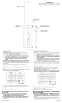
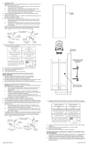
2) Attach mounting strap to outlet box. (Screws not provided).
3) Insert threaded nipple into mounting strap.
4) Attach the grounding conductor to the raised grounding lug on the back
of the xture housing. Secure by tightening the green screw. Never
connect black or white power supply wires to the grounding lug.
5) Connect the black xture wire to the black supply wire with a suitable
wire connector (not provided). Connect the white xture wire to the
white supply wire with a suitable connector.
6) Push xture to wall carefully passing the threaded nipple through hole.
7) Tighten xture to wall with threaded cap.
INSTRUCTIONS FOR MOUNTING FIXTURE OUTDOORS AND/OR IN
WET LOCATIONS.
8) Mounting surface should be clean, dry, at and 1/4” larger that the
canopy/xture on all sides. Any gaps between the mounting surface and
canopy/xture exceeding 3/16” should be corrected as required.
9) With silicone caulk, caulk completely around where back of canopy/
xture meets the wall surface to prevent water from entering the outlet box.
Antes de instalar:
Todas las instalaciones deben cumplir con los códigos locales y nacionales
de electricidad.
Si tiene alguna duda con respecto a la instalación, comuníquese con un
electricista profesional autorizado.
1) APAGUE LA ALIMENTACIÓN ELÉCTRICA.
IMPORTANTE: Antes de comenzar, NUNCA trate de trabajar sin antes
desconectar la corriente hasta que el trabajo se termine.
a) Vaya a la caja principal de fusibles, o interruptor o caja de circuitos
de su casa. Coloque el interruptor de la corriente principal en
posición de apagado “OFF”.
b) Desatornille el (los) fusible (s), o coloque el interruptor o interruptores
del breaker en posición de apagado “OFF”, que controla (n) la
corriente hacia el artefacto o habitación donde está trabajando.
c) Coloque el interruptor de pared en posición de apagado “OFF”. Si
el artefacto que se va a reemplazar tiene un interruptor o cadena
que se jala, colóquelos en la posición de apagado “OFF”.
2) Sujeta la plancha para montar a la caja de conexión. (No se proveen lost
tornillos).
3) Inserte el tube roscado en la plancha para montar.
4) Fije el conductor a tierra con la terminal de la conexión a tierra elevada
en la parte posterior de la caja del artefacto. Fije apretando el tornillo
verde. Nunca conecte los alambres de alimentación negro o blanco a la
terminal de la conexión a tierra.
5) Conecte el alambre negro de la lámpara al alambre negro de la
alimentación con un conector para alambre adecuado (no suministrado).
Conecte el alambre blanco de la lámpara al alambre blanco de la
alimentación con un conector adecuado.
6) Empuje la unidad contra la pared, pasando con cuidado el tubo roscado
a través del agujero.
7) Sujete la unidad contra la pared apretándola con la tapa roscada.
INSTRUCCIONES PARA EL MONTAJE DEL ARTEFACTO AL AIRE
LIBRE Y/O EN UN LUGAR MOJADO.
8) La supercie de montaje debe estar limpia, seca, ser plana y 1/4” más
grande que el escudete/artefacto en todos los bordes. Cualquier
espacio libre entre la supercie de montaje y el escudete/artefacto que
exceda de 3/16” debe corregirse según se requiera.
9) Calafatee totalmente con compuesto de calafatear de silicona alrededor
donde el escudete/artefacto sienta en la supercie de la pared para
impedir la entrada de agua en la caja de conexiones.
Date Issued: 4/6/12 IS-11077-US
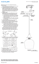
MOUNTING STRAP
PLANCHA PARA MONTAR
FIXTURE
ARTEFACTO
THREADED CAP
TAPA ROSCADA
THREADED NIPPLE
TUBO ROSCADO
OUTLET BOX
CAJA DE CONEXIÓN
INSTALLATION INSTRUCTIONS
Model 11077 / CP137593

Before Installing:
All installations should comply with National and local electrical codes.
If you have any doubts concerning installation contact a qualied licensed
electrician.
1) TURN OFF POWER.
IMPORTANT: Before you start, NEVER attempt any work without
shutting off the electricity until the work is done.
a) Go to the main fuse, or circuit breaker, box in your home. Place
the main power switch in the “OFF” position.
b) Unscrew the fuse(s), or switch “OFF” the circuit breaker switch(s),
that control the power to the xture or room that you are working on.
c) Place the wall switch in the “OFF” position. If the xture to be re
placed has a switch or pull chain, place those in the “OFF”
position.
2) Attach mounting strap to outlet box. (Screws not provided).
3) Insert threaded nipple into mounting strap.
4) Attach the grounding conductor to the raised grounding lug on the back
of the xture housing. Secure by tightening the green screw. Never
connect black or white power supply wires to the grounding lug.
5) Connect the black xture wire to the black supply wire with a suitable
wire connector (not provided). Connect the white xture wire to the
white supply wire with a suitable connector.
6) Push xture to wall carefully passing the threaded nipple through hole.
7) Tighten xture to wall with threaded cap.
INSTRUCTIONS FOR MOUNTING FIXTURE OUTDOORS AND/OR IN
WET LOCATIONS.
8) Mounting surface should be clean, dry, at and 1/4” larger that the
canopy/xture on all sides. Any gaps between the mounting surface and
canopy/xture exceeding 3/16” should be corrected as required.
9) With silicone caulking compound, caulk completely around where back
of canopy/xture meets the wall surface to prevent water from seeping
into outlet box.
Avant de procéder à l’installation:
Les installations doivent obligatoirement se conformer aux codes
d’électricité nationaux et locaux.
En cas de doute concernant l’installation, contactez un électricien certié et
qualié.
1) COUPER LE COURANT.
IMPORTANT: TOUJOURS couper l’électricité avant de commencer le
travail.
a) Localiser le coffret à fusibles ou le disjoncteur du domicile. Mettre
l’interrupteur principal en position d’Arrêt.
b) Dévisser le ou les fusibles (ou mettre le disjoncteur sur Arrêt) qui
contrôlent l’alimentation vers le luminaire ou la pièce dans
laquelle le travail est effectué.
c) Mettre l’interrupteur mural en position d’Arrêt. Si le luminaire à
remplacer est doté d’un interrupteur ou d’une chaîne connectée à
l‘interrupteur, placer ces éléments en position d’Arrêt.
2) Visser la barrette de montage à la boîte de jonction. (Vis non fournies).
3) Insérez le tube leté dans la barrette de montage.
4) Fixer le conducteur de mise à la masse à une cosse de masse relevée
située à l’arrière du boîtier du luminaire. Bloquer en serrant la vis verte.
Ne jamais connecter les ls d’alimentation blancs ou noirs à la cosse de
masse.
5) Connecter le l noir du luminaire au l noir d’alimentation à l’aide d’un
connecteur de l approprié (non fourni). Connecter le l blanc du luminaire
au l blanc d’alimentation à l’aide d’un connecteur approprié.
6) Pousser l’applique contre le mur et passser le tube leté dans le trou en
procedant avec précaution.
7) Fixer l’applique au mur à l’aide de la rondelle frein et du bouchen leté.
INSTRUCTIONS DE MONTAGE DE LUMINAIRE À L’EXTÉRIEUR ET/OU
DANS DES LIEUX HUMIDES.
8) La surface de montage doit être propre, sèche, plate et de 0,6 cm plus
épaisse que le cache/luminaire sur tous les côtés. Tout écart entre la
surface de montage et le cache/luminaire dépassant de 0,5 cm doit être
rectié selon les besoins.
9) À l’aide de matériaux d’étanchéité à la silicone, calfeutrer bien autour
où l’arrière du cache/luminaire entre en contact avec le mur pour
empêcher l’eau de passer dans la boîte de raccordement.
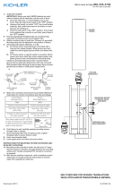
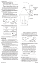
Connect Black or
Red Supply Wire to:
Connect
White Supply Wire to:
Black White
*Parallel cord (round & smooth) *Parallel cord (square & ridged)
Clear, Brown, Gold or Black
without tracer
Clear, Brown, Gold or Black
with tracer
Insulated wire (other than green)
with copper conductor
Insulated wire (other than green)
with silver conductor
*Note: When parallel wires (SPT I & SPT II)
are used. The neutral wire is square shaped
or ridged and the other wire will be round in
shape or smooth (see illus.)
Neutral Wire
Connecter le fil noir ou
rouge de la boite
Connecter le fil blanc de la boîte
A Noir A Blanc
*Au cordon parallèle (rond et lisse)
*Au cordon parallele (à angles droits el strié)
Au bransparent, doré, marron, ou
noir sans fil distinctif
Au transparent, doré, marron, ou
noir avec un til distinctif
Fil isolé (sauf fil vert) avec
conducteur en cuivre
Fil isolé (sauf fil vert) avec
conducteur en argent
*Remarque: Avec emploi d’un fil paralléle
(SPT I et SPT II). Le fil neutre est á angles
droits ou strié et l’autre fil doit étre rond ou
lisse (Voir le schéma).
Fil Neutre
Date Issued: 4/6/12 IS-11077-CB
MOUNTING STRAP
BARRETTE DE MONTAGE
INSTRUCTIONS
For Assembling and Installing Fixtures in Canada
Pour L’assemblage et L’installation Au Canada
THREADED CAP
BOUCHON FILETÉ
THREADED NIPPLE
TUBE FILETE
FIXTURE
LUMINAIRE
INSTALLATION INSTRUCTIONS
Model 11077 / CP137593
-
 1
1
-
 2
2


Kichler Lighting 11077BKT User manual
- Type
- User manual
- This manual is also suitable for
Ask a question and I''ll find the answer in the document
Finding information in a document is now easier with AI
in other languages
Related papers
-
 Kichler Lighting 49122AVI User manual
-
 Kichler Lighting 9654BK User manual
-
 Kichler Lighting 49119AVI User manual
-
 Kichler Lighting 49120AVI User manual
-
Kichler Lighting 9707BK User manual
-
 Kichler Lighting 42910PN User manual
-
 Kichler Lighting Mount Vernon 9704 User manual
-
 Kichler Lighting 43489BKSLV User manual
-
 Kichler Lighting 42474PN User manual
-
 Kichler Lighting 44008MIZ User manual


