Page is loading ...

This Installation Guide uses the following symbols to indicate important information.
Always observe the instructions indicated by these symbols.
VIGO INDUSTRIES INSTALLATION GUIDE FOR
SHOWER ENCLOSURE (MODEL VG06011)
Instructions that, if ignored, could result in death or serious personal injury caused by
incorrect handling or installation of the product. These instructions must be observed for
safe installation.
Maintenance and other important non-personal injury and non-material damage instructions
or statements that should be observed.
It is highly advised to dry fit the unit prior to any installation.
IMPORTANT
SAFETY PRECAUTIONS!
WARNING!
The instructions for the following unit is based off of the Vigo brand shower base. The
instructions can not be provided for any other installation other than that of the Vigo brand.
The warranty will be voided if the following was not performed properly.
CAUTION!
1
*VIGO reserves the right to modify/update all hardware and glass components based on
bettering the product for the end user's experience. If you have any questions contact VIGO
Tech Support at 1-866-591-7792.
REV 2 - 8/9/18

2
MODEL VG06011 MONTERAY
PLEASE READ INSTRUCTIONS BEFORE PROCEEDING
INSTALLATION INSTRUCTIONS FOR SHOWER ENCLOSURE
Parts List
1. Wall connector (2pc)
2. Longer Structural arm (1pc)
3. Shorter Structural arm (1pc)
4. Support assembly (2pc)
5. Side glass panel (1pc)
6. Front glass panel (with hinge slots, 1pc)
7. Side seal strip (2pc)
8. Glass support (4pc)
9. Bottom rail (2pc)
10. Hinge (2pc)
11. Door magnetic seal strip (2pc)
12. Bottom corner joint (1pc)
1
3
4
6
7
8
9
12
10
11
13
14
15
16
5
17
18
20
19
19
9
21
20
2
NOTE: INSTALLATION MUST BE DONE BY A QUALIFIED, LICENSED PROFESSIONAL.
GLASS THICKNESS 3/8"
13. Handle assembly (1pc)
14. Door (1pc)
15. Door side seal strip (2pc, 1 of each is extra)
16 .Door bottom seal strip (2pc, 1 of each is extra)
17. Phillips screw 1 1/8" (2pc)
18. Hex screw 1 5/8" (4pc)
19. Phillips screw 3/4" (5pc)
20. Plastic anchor green (7pc)
21. Plastic anchor white (4pc)
22. 4mm Hex screw cover (8pc)
23. Clear PVC shims (1 pack)
24. Allen key pack (1 pack)

3
MODEL VG06011
Product lines may change, contact your Vigo representative at 1-866-591-7792 or visit our
website at www.vigoindustries.com for the most up to date product line information.
1. WALL CONNECTOR
2. LONGER STRUCTURAL
ARM
4. SUPPORT ASSEMBLY
5. SIDE GLASS PANEL
7. SIDE SEAL STRIP 8. GLASS SUPPORT 10. HINGE ASSEMBLY9. BOTTOM RAIL
11. DOOR MAGNETIC
SEAL STRIP
12. BOTTOM CORNER
JOINT
13. DOOR HANDLES 14. DOOR
16. DOOR BOTTOM SEAL
STRIP
A
B
C
15. DOOR SIDE SEAL
STRIP
6. FRONT GLASS PANEL
98007
98068-3232
98068-3636
98068-3240
98068-3248
98068-3648
98009
97003-32
97003-36
97004-32
97004-36
97004-40
97004-48
96001
98010
98011
95002-32x32
95002-32x40
95002-32x48
95002-36x36
95002-36x48
96011
94004 98012-15
98012-18
96006
96004
97010-32
97010-36
97010-40
97010-48
19. PHILLIPS SCREW
3/4"
18. HEX SCREW 1 5/8"
17. PHILLIPS SCREW 1 1/8"
PLASTIC ANCHOR
20.
PLASTIC ANCHOR
21.
98038
98037
98033
98039
98035
4mm HEX SCREW
COVER
22.
96040
3. SHORTER
STRUCTURAL ARM
98069-3232
98069-3636
98069-3240
98069-3248
98069-3648
A, B & C DIMENSIONS WERE MEASURED AFTER SHOWER ENCLOSURE WAS COMPLETELY INSTALLED
33 1/8"x71 5/8"
29 1/4"x71 5/8"
22 7/8"x70 3/4"
10 1/8"x71 5/8"
14 1/8"x71 5/8"
29 1/4"x71 5/8" 21 1/4"x71 5/8"
23 5/8"x70 3/4"
22 7/8"x70 3/4"
33 1/8"x71 5/8"
23 5/8"x70 3/4"
21 1/4"x71 5/8"
34 1/8" 34 1/8"
30 1/4" 38 1/4"
34 1/8"
46"
30 1/4"
46"
29 1/4"x71 5/8"
19 3/4"x70 3/4"
9 1/2"x71 5/8"30 1/4" 30 1/4"
DIM. "A" DIM. "B"
MODEL
#5- SIDE GLASS
PANEL (97003)
#14- DOOR (97010)
#6- FRONT GLASS
PANEL (97004)
36 X 36
32 X 48
DIM. "C"
* - GLASS AND HARDWARE ONLY (FULLY INSTALLED)
HEIGHT
73 3/8"
73 3/8"
32 X 40
73 3/8"
36 X 48
73 3/8"
32 X 32
73 3/8"
22 7/8"
22 7/8"
23 3/4"
23 3/4"
19 3/4"
CLEAR PVC SHIM
MISC
23.
ALLEN KEY PACK
MISC
24.
24 1/4"
23 7/16"
24 1/4"
DOOR OPENING
WIDTH
23 7/16"
20 1/4"

4
MODEL VG06011
WARNING
WE STRONGLY RECOMMEND THAT A LICENSED PROFESSIONAL INSTALL THIS SHOWER
ENCLOSURE AND INCLUDE THE ASSISTANCE OF A SECOND PERSON TO INSTALL THE DOOR UNIT.
!
INSTALLATION OF THE SHOWER DOORS BY AN INEXPERIENCED PERSON MAY RESULT IN GLASS
BREAKAGE AND, CONSEQUENTLY, CAUSE PERSONAL INJURY OR DEATH.
- Handle fragile items with care to prevent personal injury or material damage.
- The glass panels are tempered and cannot be cut. Never attempt to do so.
- Always rest glass on a level surface
BEFORE STARTING
Compare items on your invoice with what you have received. Carefully review the Packing List on page 2. If
any items are missing contact Vigo Industries at 1-866-591-7792. Please check our website at
www.vigoindustries.com for additional information or instructional videos.
REQUIRED TOOLS
Square and/or Phillips #1 and #2 screwdriver
Flat head screwdriver
Electric drill plus 1/32", 3/32", 1/8" and 1/4" drill bit (depending on wall)
Level
Measuring tape
Pencil (non-permanent)
Clear silicone caulking
Utility knife
Shims (not provided)
IMPORTANT:
THE CLEAR GLASS MODEL HAS A REVERSIBLE DOOR AND CAN BE INSTALLED TO THE RIGHT OR LEFT SIDE.
(SEE CONFIGURATION DIAGRAM BELOW)
IMPORTANT
Fiberglass, acrylic or sheetrock construction might not be sufficiently strong enough to support the
shower door enclosure. You should use the wood framing studs from behind the face edge of the stall to
provide a secure mounting to the door. Apply a bead of silicone between the walls and base of the stall.
For optimum performance, you should install the shower door perfectly level on a level surface. Failure to
do so will lead to water leakage and potential property damage.
When installing use heavy duty gloves.
LEFT CORNER
INSTALLATION
RIGHT CORNER
INSTALLATION
DOOR
DOOR
FRONT GLASS
PANEL
DOOR PANEL SIDE GLASS
PANEL
FRONT GLASS
PANEL
DOOR PANELSIDE GLASS
PANEL
5 5146614
FIG. 1A (GLASS CONFIGURATION DIAGRAM)

5
MODEL VG06011
STUD
FIG.1
PREPARATION STEPS TO FOLLOW BEFORE INSTALLATION
IMPORTANT
To prevent damage to the finish, you should protect the shower cabin bottom with a cardboard
protector before beginning the installation.
Ensure that there is sufficient structural support behind the shower wall to hold the weight of the
shower door. If there is insufficient support, then reinforce the shower walls with wooden studs
prior to shower door installation. [SEE FIG.1]
1. Remove the plastic layer from the base border (if needed). Do NOT remove the plastic layer off
the plastic platform of the base.
2. Properly apply silicone to the wall and base joints.
3. Make sure to read corresponding base instructions carefully prior to install on the Vigo Brand
Shower Door System. Failure to do so can cause water leakage and bodily harm.
CAUTION
!
GASKETS NEED TO BE IN BETWEEN ALL GLASS AND METAL CONTACT. FAILURE TO
DO SO CAN LEAD TO BREAKAGE AND POTENTIAL BODILY HARM.
LEFT DOOR INSTALLATION
RIGHT DOOR INSTALLATION

6
MODEL VG06011
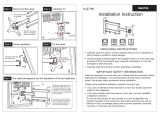
INSTALLATION STEPS
A1
A2
A. INSTALLING THE BOTTOM RAIL
1. Remove the aluminum cover from the front
piece of the bottom rail by sliding it out.
2. Remove top of the corner joint. Slide the
bottom corner joint (#12) onto the bottom
rail (2 pieces) (#9).
3. Align the bottom rail and corner joint to the
desired position on the shower base.
There should be a 90 degree angle where
the rails meet. Make sure the A and B
distances are correct (see page 3 for A
and B distances). Prior to drilling, dry fit
everything making sure that everything is
straight, level and plum. Pre-drill for
sinkers and tap sinkers. Cut excess sinker
off with hacksaw or sharp blade. Dip
screws in silicone. Screw corner joints and
rails down. Silicone tops of screws.
OUTSIDE
INSIDE
ALUMINUM COVER
9
11
THIS EDGE LOOKS
OUTSIDE OF THE SHOWER
THIS EDGE LOOKS
INSIDE OF THE SHOWER
TOP REMOVES TO
INSTALL 3/4" SCREW
A3
A
B
19
17

7
MODEL VG06011
4.
Seal the bottom rail with clear silicone caulk
and center its sides to the base.
5. Clip the aluminum cover to the front piece
of the bottom rail making sure the lower
side faces the inside of the shower. Silicone
the underneath portion of the corner joint
cap and place it on the corner joint.
A4
A5
OUTSIDE
INSIDE
ALUMINUM COVER
INSIDE
OUTSIDE
CORNER
JOINT CAP

8
MODEL VG06011
B1
1. Clean the front fixed panel (#6) edge where
the door side seal strip (#15) is to be
installed with rubbing alcohol. Verify that
the soft flange of the seal strip faces toward
the inside of the shower cabin before seal
strip installation. Install the seal strip
according to the diagram. See Note: A.
Leave the extra at the top of the seal strip
that is overlapping the glass and cut at
finish of install.
NOTES:
1. If the seal strip is not flat and is twisted, soak
the strip in hot water and press the seal strip
back into position.
2. Part #15 is reversible and pre-cut on top and
bottom to fit in proper configuration.
Cutting/finishing is needed but only after
fully installing and only at the top of the unit.
3. The door magnetic seal strip (#11) and the
side seal strips (#7) will be 10mm shorter
than the front glass panel. This is to
compensate for the depth of the bottom rail.
The door magnetic seal strip (#11) is
reversible and will need to be cut at top for
best aesthetic approach.
B. INSTALLING THE WATER SEAL STRIP TO FRONT FIXED PANEL
THIS SIDE MUST
LOOK INSIDE
THE CABIN
6
6
15
NOTE: A
MAKE SURE TO
LEAVE A GAP OF
3/8" [10MM] FROM
THE BOTTOM OF
THE GLASS
7
3/8"
[10mm]

9
MODEL VG06011
C1
1. Arrange glass to the preferred
configuration. [SEE FIG.1A on page 4]
These instructions are for a left
corner installation. Select the door
opening location on the shower cabin.
Install the seal strip (#7) to the wall side of
the front glass panel (#6).
2. Screw in the glass support (#8) to the front
glass panel (#6) using the hex key
(supplied) making sure to slide it back as
far as possible from the glass before you
tighten. The part that connects to the wall
should be facing in. Be sure to use gaskets
on both sides of the panel.
C. INSTALLING THE FRONT GLASS PANEL
3/8"
[10mm]
C2
THIN
GASKETS
8
8
7
WALL
SIDE
6
MAKE SURE TO
LEAVE A GAP OF
3/8" [10MM] FROM
THE BOTTOM OF
THE GLASS
15

10
MODEL VG06011
3. Place the front glass panel (#6) into the
bottom rail (#9). Use the level to position
the front glass panel correctly. Make sure
the seal strip (#7) is against the wall. Mark
holes on the wall for the mounting screws.
4. Remove the front glass panel. Drill holes
into the respective marks and insert plastic
anchors (#21) inside them. Not
necessary if installing into studs. Studs
are the preferred means of installation,
anchors can pull out of the wall causing
property damage and bodily harm.
C3
C4
6
8
7
9
21
!
THIS SIDE
MUST BE
LEVEL

11
MODEL VG06011
5. Replace the front glass panel (#6) back into
the bottom rail and screw it to the wall with
the with 1 5/8" screws (#18). If the panel is
not level from the end, adjust the position
of the glass supports on the glass. This
being level is imperative to the installation.
There is a 10mm adjustment built into the
glass supports for minor modifications.
C5
6
8
9
18
10mm ADJUSTMENT
8
THIS SIDE
MUST BE
LEVEL

MODEL VG06011
12
D2
THIN
GASKETS
VIEW FROM
INSIDE
FRONT
GLASS
PANEL (6)
HINGE (10)
INSIDE VIEW
FRONT
GLASS
PANEL (6)
CLEAR
PVC SHIM
SEAL
STRIP (15)
HINGE (10)
FRONT
GLASS
PANEL (6)
CLEAR
PVC SHIM
INSIDE VIEW
HINGE (10)
D. INSTALLING THE HINGE
1. Clean the glass surface on the front glass
panel (#6) where the hinges (#10) are to
be installed with rubbing alcohol. Place
gaskets on each side of the front glass
panel (#6). Position hinges on the front
glass panel (#6). Place a shim(s) as
needed between the glass and the hinge
on the bottom. The metal should not rest
on the glass.
2. Screw the hinges to the front glass panel
with the hex key (supplied).
D1

13
MODEL VG06011
HEX SCREW
FRONT GLASS
PANEL (6)
DOOR (14)
THIN
GASKET
VIEW FROM THE TOP
HINGE (10)
OUTSIDE OF
THE CABIN
INSIDE OF
THE CABIN
PLATE
THIN
GASKETS
THIN
GASKET
SEAL STRIP
(15)
WARNING
!
DOOR PANEL INSTALLATION REQUIRES
TWO OR MORE PEOPLE TO ASSIST
E. INSTALLING THE DOOR
1. Place the door on a 5/8" shim (not
provided). Install the top hinge first for
safety and ease of install. Position the
door onto the hinges. Hold securely in
place using shims. The seal (#15) may
get stuck between the two panels of
glass. Pull the seal out of the groove
using your fingers and nothing sharp,
making sure not to damage the seal.
Tighten allen key screws. Install the
hinges as illustrated. Use the hex key
supplied. Adjust hinge so the gaps are
equal at top and bottom and pull door
panel away from front panel (#6) to allow
the door to swing freely without crimping
seal strip (#15).
2. Lift door panel to be level with hinge
panel. Use PVC shims provided to hold
firmly in place. NOTE - You may need
to add more than one shim per hinge
as glass hole openings vary during
production. PVC shims prevent the
door from sagging due to gravity and
the weight of the door. Never install
without shims, this can cause the
glass to break causing property
damage and bodily harm.
E1
!
E2
VIEW FROM
INSIDE
INSIDE VIEW
CLEAR
PVC SHIMS
HINGE (10)
DOOR (14)
INSIDE VIEW
DOOR (14)
CLEAR
PVC SHIM
HINGE (10)

MODEL VG06011
14
E3
3. Make sure the door is level from the end.
If the door is not level, adjust the hinge
positions until the door is level. This being
level is imperative to the installation and will
guarantee a tight seal.
4. Clean the door (#14) glass surfaces where
the hinges (#10) are to be installed with
rubbing alcohol. Place magnetic seal strip
(#11) to the panel. The magnetic side
should be facing the inside and the clear
side be facing the outside. Do not install
the handle first, this is dangerous and may
cause the glass to break. The door
magnetic seal strip (#11) is reversible and
will need to be cut at top for best aesthetic
approach.
THIS SIDE
MUST BE
LEVEL
11
E4
14
14

15
MODEL VG06011
F1
1. Install the side seal strip (#7) to the wall
side of the side glass panel (#5). Install the
magnetic side seal strip (#11) to the door
side. The magnetic side should be facing
the inside and the clear side be facing the
outside. Be sure to place the seal strip
(#7) 10mm from the bottom of the glass.
Installing the magnetic seal strip prior to
locating the place for the glass support
allows for proper seal. You may need to
adjust the magnetic seal strip placement
after full install to guarantee proper
placement on the top of the corner joint. It
should rest tight on the corner joint in order
to prevent water leakage.
2. Screw in the glass support (#8) to the side
glass panel (#5) using the hex key
(supplied). Be sure to use gaskets on both
sides of the panel. Do not completely
tighten. Leave rather loose so they can
slide on the glass panel
F. INSTALLING THE SIDE GLASS PANEL
F2
11
7
WALL
SIDE
DOOR
SIDE
5
MAKE SURE TO
LEAVE A GAP OF
3/8" [10MM] FROM
THE BOTTOM OF
THE GLASS
3/8"
[10mm]
!
THIN
GASKETS
8
7
5
8

MODEL VG06011
16
3. Place the side glass panel (#5) into the
bottom rail (#9). Connect the side glass
panel (#5) to the door (#14) by the
magnetic seal strips (#11).
4. One person must hold the connection at
the magnetic seal strips (#11) in place. The
other person, with the glass supports loose
on the glass, will slide the supports along
the glass to the wall and mark holes on the
wall for the mounting screws.
F3
F4
9
11
5
14
9
11
5
14
MAGNETIC SEAL
STRIP CONNECTION
WILL BE HELD HERE
BY ONE PERSON
DURING THIS
ENTIRE STEP.
9
11
5
14
SECOND PERSON
SLIDES THE GLASS
SUPPORTS ALONG
THE GLASS UNTIL
THEY MEET THE
WALL.

17
MODEL VG06011
5. Remove the side glass panel. Drill holes
into respective marks and insert plastic
anchors (#21) inside them. Not
necessary if installing into studs. Studs
are the preferred means of installation,
anchors can pull out of the wall causing
property damage and bodily harm.
F5
6. Replace the side glass panel (#5) back
into the bottom rail and screw it to the wall
with 1 5/8" screws (#18). Tighten the glass
supports to the side glass panel. NOTE:
One person should be holding the side
panel and door panel closed (with the
magnetic seal strips on) while the other
person screws in the glass supports.
This will ensure a proper seal. If the
door and side panel pull away at the
seal, then it is recommended to modify
the position of the glass supports along
the glass or thickness of gaskets
between the wall and glass support. This
is done by adding or removing the clear
PVC gaskets and sliding the glass
support, in a perpendicular direction
closer or further from the wall.
!
9
14
21
F6
9
11
5
14
18

18
MODEL VG06011
G. INSTALLING THE SIDE & FRONT PANEL SUPPORT
G1
1. Install the support assembly (#4) onto the
side glass panel (#5) approximately
two-thirds away from the wall. Be sure to
use gaskets on both sides of the panel.
Use hex key to tighten to screws.
2. Install the support assembly to the longer
structural arm (#2) and wall connector (#1).
Make sure it's level. Mark the hole on the
wall for the mounting screw for the wall
connector.
WALL
SIDE PANEL
OUTSIDE OF
THE CABIN
WALL
G2
SIDE PANEL
WALL
4
SIDE PANEL
2 or 3
1
4
LEVEL

19
MODEL VG06011
3. Remove the support assembly. Drill a hole
into the respective mark and put a plastic
anchor (#20) in it. Not necessary if
installing into studs.
4. Replace wall connector to proper position.
Screw it in to the wall with 1 1/8" screws
(#17).
5. Slide the structural arm (#2) into the wall
connector (#1). Tighten all set screws.
Repeat steps 1 through 5 to install the other
support assembly to the front fixed panel
(#6) with the shorter structural arm (#3).
G3
!
G4
G5
4
WALL
SIDE PANEL
1
SIDE PANEL
WALL
4
20
SIDE PANEL
WALL
1
4
LEVEL
17
2 or 3
2 or 3

14
11
H. INSTALLING PRE-CUT BOTTOM DOOR SEAL STRIP
1. Clean the door glass panel (#14) edge where
the door bottom side seal strip (#16) is to be
installed with rubbing alcohol. Verify that the
soft flange of the seal strip faces toward the
inside of the shower cabin before seal strip
installation. Install the seal strip according to
the diagram.
NOTES:
1. If the seal strip is not flat, use a hair dryer to
apply minimal heat and press the seal strip back
into position.
2. Adjust the magnetic seal strips (#11) to the
correct height over the corner joint and cut to the
needed height at the top of the panels.
H1
11
16
14
14
OUTSIDE OF
THE CABIN
11
16
16
MODEL VG06011
20
/