Mitsubishi Electric LU-ST KIT User manual

Category
Sewing machines
Type
User manual

Mitsubishi Electric LU-ST KIT is an industrial sewing machine attachment that effectively shortens tail lengths after trimming. It eliminates the need for additional hand trimming, increasing production and preventing damage to sewn parts caused by hand trimming. The Mitsubishi genuine knife mechanism ensures reliable and durable trimming. Installation is straightforward and doesn't require any machining. The kit includes all necessary parts, including a new feed dog, fixed knife, needle plate, thread trimmer cam, and air cylinder assembly.

Mitsubishi Electric LU-ST KIT is an industrial sewing machine attachment that effectively shortens tail lengths after trimming. It eliminates the need for additional hand trimming, increasing production and preventing damage to sewn parts caused by hand trimming. The Mitsubishi genuine knife mechanism ensures reliable and durable trimming. Installation is straightforward and doesn't require any machining. The kit includes all necessary parts, including a new feed dog, fixed knife, needle plate, thread trimmer cam, and air cylinder assembly.

LOCKSTITCH COMPOUND-FEED AUTOMATIC UNDERTRIMMER
INDUSTRIAL SEWING MACHINE
Attachment
MODEL
LU-ST KIT
INSTRUCTION MANUAL
Short Thread Tail Device for LU2-4410
A180E547P03
- 1 -
FOR YOUR SAFETY!
If you operate this attachment first time, please make sure to read the following instructions for
your safety and proper operation.
Explanations for the warning signs
No
Warning sign Meanings of warning sign
1
Caution for sewing machine operation
Warning to operate the sewing machine without safety
guards and to prohibit doing any operation except sewing
while the power is turned ON.
2
Caution for the fingers to be caught in the machine
Warning to a possible danger
to be caught the fingers in the
machine under the specified operation.
1. Features
1. This device is designed to effectively shorten the tail lengths after trimming.
2. The LU-ST kit attaches to the machine without any machining.
3. The elimination of additional hand trimming will increase production.
4. Any damage to sewn parts caused by hand trimming will be eliminated.
5. The Mitsubishi genuine knife mechanism provides a reliable and durable trim function.
2. Correspondence model
Type
Correspondence
Control box
LU-ST KIT LU2-4410-B1T-CS XC-GMFY
* A sewing machine made in before April 1995 doesnt correspond to LU-ST KIT.
3. Specification
1. Max. stitch length is limited to 8mm.
2. The air inlet diameter is 8mm.
3. The air regulator and branch device are not enclosed with this kit and must be prepared by the user.
This instruction manual explains the instructions how to operate and maintain the sewing
machine.
All information in this instruction manual are subject to change without notice.
MITSUBISHI ELECTRIC CORPORATION has all the copy rights on this instruction manual.
Reprinting the parts or all of this instruction manual is not allowed without permission.
From the library of Superior Sewing Machine & Supply LLC - www.supsew.com
- 2 -
4.Component Parts
LU-ST KIT is composed under mentioned parts. (Fig No. corresponds to following
figures.) Please specify (M) by the part number for a service parts when you order.
Parts No.
Description
Amt. Req.
MP69A0104
Feed dog
1
MP69A0838
Fixed knife
1
MP69A0101
Needle plate
1
MP47A0567
Urethane tube
2
MP69A0350
Thread trimmer cam
1
MP69A0841
Stitch length indicating plate
1
M90409041
Wood screw
2
MP69A0434
Air cylinder assembly
1
M96062021
Screw
4
MP69A0601
Mounting plate
1
M95003017
Bolt
4
M90519050
Nylon washer
2
MP69A0603
Bracket
1
MP69A0237
Back cover
1
MP69A0910
Driving link
1
M91502045
Nut
1
M91503031
Bolt
3
MP69A1910
Link
1
M90910060
Pin
1
M91066004
Screw
4
MP69E0599
Solenoid valve assembly
1
MH25A1601
Solenoid value mounting plate
1
The parts marked as D** in the drawing cannot be used after this kit is installed.
However, these must be used when returning to the standard specifications, so store
them in a safe place. Moreover, parts of “R** have already been installed in the
sewing machine head.
From the library of Superior Sewing Machine & Supply LLC - www.supsew.com
LU-ST KIT Component Parts
- 3 -
From the library of Superior Sewing Machine & Supply LLC - www.supsew.com
- 4 -
5. Installation procedure of LU-ST KIT
5.1 Exchange of thread trimmer cam.
(1) Lean the sewing machine backwards.
(2) Loosen the screw of bush (R01).
(3) Loosen the screw of bush (R02).
(4) Loosen the screw of feed cam (R03).
(5) Loosen the screw of bush (R04).
(6) Loosen the screw of the large gear (R05).
(7) Loosen the screw of eccentric cam (R06).
(Lift the sewing machine and loosen the screw from the back side.)
(8) Loosen the screw of bush (R07).
(9) Loosen the screw of spring holder (R08). And then detach the coil (R09) spring and
pin (R10), and move the lower shaft right to the place where thread trimmer cam (D01)
remove with bush (R04) and thread release cam (R11).
(Remove the eccentric cam (R06) and the large gear (R05).)
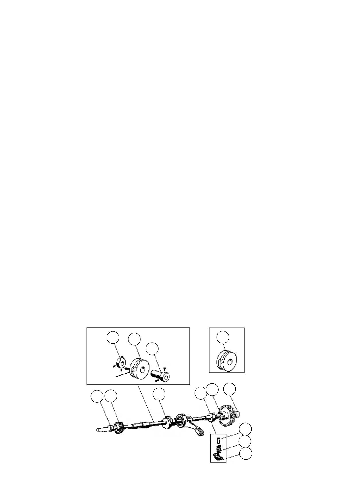
(10) Remove the thread trimmer cam (D01) with bush (R04) and thread release cam (R11).
At that time, if the installation angle of the cam and bush is recorded, re-assembly work
become easy.
(11) Loosen the screw of thread release cam (R11), and then remove the thread release cam (R11)
with bush (R04) and thread trimmer cam (D01). Exchange the thread trimmer cam (D01) for
the kit one (105). In thread trimmer cam (105) of the kit has mark "2" to the side.
Install bush (R04) in the direction of the figure below. Afterwards, install thread release cam (R11).
(12) Pass assembled the bush assembly (R04, 105, R11) through the lower shaft.
(13) Move the lower shaft left slowly.
(14) Fix the large gear (R05). (Install it in the direction of the figure below.)
(15) Fix the eccentric cam (R06).Tighten the screw in the groove of the shaft at the right of
the feed bar connecting fork beforehand.
(16) Move the lower shaft left and return it to former position.
(17) Put the first screw in the set of lower shaft, and then tighten all of the loosened screw.
(Tighten the screw of bush (R07) finally.)
R11
D01
R04
105
R06
R05
R03
R02
R01
R07
R10
R09
R08
SCREW
From the library of Superior Sewing Machine & Supply LLC - www.supsew.com
- 5 -
5.2 Installation of air cylinder assembly.
(1) Remove the snap pin (R12), remove the knee lifter connecting rod (R14) from the knee lifter
crank assy (R13).
(2) Remove the rubber plug (R15).
(3) Remove the back cover (D02).
(4) Loosen the two screw (R17) of the feed regulator cam (R16) seen when the rubber plug (R15) and
the back (D02) cover are removed. And, pull out the pin (D03).
Note do not remove screw (R17).
(5) Match the hole of the driving link (R18) and the hole of feed regulator cam (R16) and fix
the pin (119).
(Fit the hole of feed regulator cam (R16) to the hole of driving link (R18) moving driving link
up and down and back and forth. Lean arm when driving link (R18) does not move back and forth
and rotate the reverse bracket.)
(6) Match the set of pin (119) and the screw (R17) of the feed regulator cam (R16) and tighten a right screw
previously. Tighten the screw after confirming the screw fits in the set.
R15
R13
R12
R14
D02
D03
R18
R16
R17
R17
R16
R18
SET
119
From the library of Superior Sewing Machine & Supply LLC - www.supsew.com
- 6 -
(7) Match the back cover (114) to arm and tighten the screw on the left of the back cover (114) loosely.
(8) Take out the driving link (115) from the groove of the back cover (114).
(Pull the knuckle to the point in the under.)
(9) Fix the groove in the point of the driving (115) link into the pin between nylon washer and
nylon washer.
(10) Match the screw hole of the bracket (113) and the hole of the driving link (115) and tighten
the bolt (117).
(11) Take out the machine head support on the table.
(12) Tighten all the screws of the back cover (114). and, it is assembly completion.
5.3 Exchange of feed dog, fixed knife, and needle plate.
Exchange parts of the figure below which you have for the one (101, 102, 103) of the accessory.
102
103
101
GROOVE
KNUCKLE
NYLON
WASHER
115
117
114
113
From the library of Superior Sewing Machine & Supply LLC - www.supsew.com
- 7 -
5.4 Installation of solenoid valve
(1) Connect the urethane tube (104) with elbow unions of air cylinder assembly (108).
(2) Install solenoid value assembly (121) on the place where urethane tube (104) and under the table
reach.
(3) Connect the upper part of elbow unions installed on the air cylinder assembly (108)
with A port of the solenoid valve assembly (121) by the urethane tube (104).
Similarly, connect the lower side of elbow unions and B port of the solenoid
valve assembly (121) by the urethane tube (104).
(4) Connect the connector of solenoid value assembly (121) with option B of the control board.
(5) Connect the air supply source to the P port of the solenoid value.
(6) Use the regulator and the branch device which you prepared.
5.5 Exchange of stitch length indicating plate.
(1) Turn the dial left and make the stitch length indicating plate to 0 points.
(2) Loosen the screw at the center of the dial and remove the dial.
(3) Remove the stitch length indicating plate (D04) from the dial
and fix stitch length indicating plate (106) of this kit into the dial.
(4) Make 0 points of the dial just above. after that, tighten the screw to install the dial.
B-PORT
ELBOW
UNIONS
108
121
A-PORT
CONNECTOR
104
0 POINTS
106
D04
0 POINTS
From the library of Superior Sewing Machine & Supply LLC - www.supsew.com
- 8 -
6. Adjustment of thread trimmer cam
Refer to Adjusting of thread trimmer cam of instruction manual for LU2-4410.
7. Timing between rotating hook motion and needle motion
Refer to Adjusting of timing between rotating hook motion and needle motion of the instruction manual for
LU2-4410.
8. Initial position of movable knife
When you install this kit, the position need not be adjusted.
Refer to install of movable knife of the manual for the exchange of the movable knife .
However, the adjustment of the movable knife changes because
the shape of the fixed knife changed.
Adjust to hide the point of the movable knife from the point
of the blade of the fixed knife by 0-0.5 mm.
102
From the library of Superior Sewing Machine & Supply LLC - www.supsew.com
- 9 -
9. Adjusting of the stitch length before trimming
Depending on sewing conditions, the stitch immediately before trimming may not be formed correctly.
This may cause the trimmed tail length to be long.
In this case, adjust the length of the stitch immediately before the trimming position to ensure that a
proper stitch is formed. As reference, the standard stitch length is 1 to 2 mm. The length of the stitch
immediately before trimming can be adjusted by moving the position of the knuckle to the air cylinder
shaft up/down. Adjust with the following methods.
(1) Loosen the nut on the knuckle.
(2) Rotate the air cylinder shaft.
Adjust the position of the knuckle to the air cylinder shaft.
(3) The stitch immediately before trimming is as follows.
During forward stitching: Looking from above, turn the shaft clockwise to change to reverse stitching.
Too short during reverse stitching: Looking from above, turn the shaft clockwise.
Too long during reverse stitching: Looking from above, turn the shaft counterclockwise.
The stitch length changes about 1 mm when the shaft is rotated once.
In the position of the knuckle when shipping, dimension A between the lower surface of the air cylinder and
the upper surface of the knuckle is 19 mm like the below figure with the air cylinder drawn in.
10. Setting up the XC-GMFY control box
Set the control box to machine model LU2-4412 by simple setting function.
AXIS
NUT
KNUCKLE
A
From the library of Superior Sewing Machine & Supply LLC - www.supsew.com
MEMO
From the library of Superior Sewing Machine & Supply LLC - www.supsew.com
Printed in Japan
From the library of Superior Sewing Machine & Supply LLC - www.supsew.com
  • Page 1 1
  • Page 2 2
  • Page 3 3
  • Page 4 4
  • Page 5 5
  • Page 6 6
  • Page 7 7
  • Page 8 8
  • Page 9 9
  • Page 10 10
  • Page 11 11
  • Page 12 12

Mitsubishi Electric LU-ST KIT User manual

Category
Sewing machines
Type
User manual

Mitsubishi Electric LU-ST KIT is an industrial sewing machine attachment that effectively shortens tail lengths after trimming. It eliminates the need for additional hand trimming, increasing production and preventing damage to sewn parts caused by hand trimming. The Mitsubishi genuine knife mechanism ensures reliable and durable trimming. Installation is straightforward and doesn't require any machining. The kit includes all necessary parts, including a new feed dog, fixed knife, needle plate, thread trimmer cam, and air cylinder assembly.

Ask a question and I''ll find the answer in the document

Finding information in a document is now easier with AI