Page is loading ...

Reference
Manual
DOC. REV. 9/21/2016
EPM-15
(Manx)
AMD LX Based SBC with
Ethernet, Video, and PC/104-
Plus interface

EPM-15 Reference Manual ii
WWW.VERSALOGIC.COM
4211 West 11th Ave.
Eugene, OR 97402
(541) 485-8575
Fax (541) 485-5712
Copyright © 2010 VersaLogic Corp. All rights reserved.
Notice:
Although every effort has been made to ensure this document is error-free, VersaLogic makes no
representations or warranties with respect to this product and specifically disclaims any implied warranties
of merchantability or fitness for any particular purpose.
VersaLogic reserves the right to revise this product and associated documentation at any time without
obligation to notify anyone of such changes.
PC/104 and the PC/104 logo are trademarks of the PC/104 Consortium.

EPM-15 Reference manual iii
Product Release Notes
Rev 6 Release – Updated Figure 7.
Rev 5 Release – The power connector (J9) was moved slightly to match the position of the power
connector on the VL-EPM-5 (see page 18).
Rev 4 Release – New audio codec and Ethernet chips incorporated as a result of component
obsolescence.
Rev 3 Release – Commercial release.
Rev 2 Release – Beta release.
Rev 1 Release – Pre-production only. No customer releases.
Support Page
The EPM-15 support page, at http://www.versalogic.com/private/manxsupport.asp, contains additional
information and resources for this product including:
Reference Manual (PDF format)
Operating system information and software drivers
Data sheets and manufacturers’ links for chips used in this product
BIOS information and upgrades
Utility routines and benchmark software
Note: This is a private page for EPM-15 users that can be accessed only be entering this address directly.
It cannot be reached from the VersaLogic homepage.

EPM-15 Reference Manual iv
Contents
Introduction ................................................................................................................... 1
Description .......................................................................................................................... 1
Features and Construction ..................................................................................... 1
Technical Specifications ..................................................................................................... 2
EPM-15 Block Diagrams .................................................................................................... 3
RoHS Compliance .............................................................................................................. 5
About RoHS ........................................................................................................... 5
Warnings ............................................................................................................................. 5
Electrostatic Discharge .......................................................................................... 5
Lithium Battery ...................................................................................................... 5
Handling Care ........................................................................................................ 6
Technical Support ............................................................................................................... 7
Repair Service ........................................................................................................ 7
Configuration and Setup ............................................................................................... 8
Initial Configuration ........................................................................................................... 8
Basic Setup ......................................................................................................................... 8
CMOS Setup ..................................................................................................................... 11
Operating System Installation ........................................................................................... 12
Physical Details ........................................................................................................... 13
Dimensions ....................................................................................................................... 13
EPM-15 Dimensions and Mounting Holes .......................................................... 13
CBR-5010 Dimensions and Mounting Holes ...................................................... 14
Hardware Assembly ............................................................................................. 15
Stack Arrangement Example ............................................................................... 15
EPM-15 External Connectors ........................................................................................... 16
EPM-15 Connector Locations – Bottom ............................................................. 17
EPM-15 Connector Functions and Interface Cables ........................................... 18
Breakout Board Connectors .............................................................................................. 19
CBR-5010 Connector Locations .......................................................................... 19
CBR-5010 Connector Functions and Mating Connectors ................................... 19
Jumper Blocks .................................................................................................................. 20
Jumpers As-Shipped Configuration ..................................................................... 20
Jumper Summary ................................................................................................. 21
System Features .......................................................................................................... 22
Power Supply .................................................................................................................... 22
Power Connectors ................................................................................................ 22
Power Requirements ............................................................................................ 23
Lithium Battery .................................................................................................... 23
CPU ................................................................................................................................... 23
System RAM ..................................................................................................................... 23
CMOS RAM ..................................................................................................................... 24

Contents
EPM-15 Reference manual v
Clearing CMOS RAM ......................................................................................... 24
CMOS Setup Defaults ...................................................................................................... 24
Default CMOS RAM Setup Values ..................................................................... 24
Real Time Clock ............................................................................................................... 24
Setting the Clock.................................................................................................. 24
ACPI Power Management ................................................................................................ 25
The S3 Sleeping State .......................................................................................... 25
Setup .................................................................................................................... 25
Entering Standby Mode ....................................................................................... 25
Wakeup ................................................................................................................ 26
Interfaces and Connectors ......................................................................................... 27
Serial Ports ........................................................................................................................ 27
COM Port Configuration ..................................................................................... 27
COM3 and COM4 RS-485 Mode Line Driver Control ....................................... 27
IDE Hard Drive / CD-ROM Interfaces ............................................................................. 28
J8 Utility Connector .......................................................................................................... 29
USB Interface ...................................................................................................... 30
Programmable LED ............................................................................................. 30
IDE LED .............................................................................................................. 30
Internal Speaker ................................................................................................... 30
Push-Button Reset ............................................................................................... 30
Parallel Port ...................................................................................................................... 31
Video Interface ................................................................................................................. 32
Configuration ....................................................................................................... 32
Video BIOS Selection.......................................................................................... 32
SVGA Output Connector ..................................................................................... 32
LVDS Flat Panel Display Connector ................................................................... 33
Compatible LVDS Panel Displays ...................................................................... 34
Console Redirection ............................................................................................ 34
Ethernet Interface.............................................................................................................. 36
BIOS Configuration ............................................................................................. 36
Status LED ........................................................................................................... 36
Ethernet Connector .............................................................................................. 36
Audio ................................................................................................................................ 37
Software Configuration ....................................................................................... 37
CPU Temperature Monitor ............................................................................................... 37
PC/104 Expansion Bus ..................................................................................................... 38
PC/104 I/O Support ............................................................................................. 38
PC/104 Memory Support ..................................................................................... 38
IRQ Support ......................................................................................................... 38
DMA Support ...................................................................................................... 38
System Resources and Maps ..................................................................................... 39
Memory Map .................................................................................................................... 39
I/O Map ............................................................................................................................. 39
Interrupt Configuration ..................................................................................................... 40
Special Registers ........................................................................................................ 41
Special Control Register ................................................................................................... 41

Contents
EPM-15 Reference Manual vi
Revision Indicator Register .............................................................................................. 42
Jumper and Status Register ............................................................................................... 43
RS-485/422 Transmit/Receive Control Register .............................................................. 44
Appendix A – References............................................................................................ 45
Appendix B – Generated Frequencies ....................................................................... 46

EPM-15 Reference Manual 1
Introduction
Description
FEATURES AND CONSTRUCTION
The EPM-15 is a feature-packed single board computer (SBC) designed for OEM control
projects requiring fast processing and designed-in reliability and longevity (product lifespan). Its
features include:
AMD LX microcontroller
256 MB soldered on system DDR
SDRAM
CompactFlash site
10/100 Ethernet interface
Flat Panel Display support
PC/104 (ISA) and PC/104-Plus (PCI)
expansion
ATA-5 IDE controller
Four USB 2.0 ports for keyboard,
mouse, floppy, and other devices
TVS devices for ESD protection
Parallel port
Audio
CPU temperature sensor
One RS-232 COM port and two
RS422/485 COM ports
VCC sensing reset circuit
Field upgradeable BIOS with OEM
enhancements
ACPI standby mode (suspend to RAM)
Customizing available
Low-power fanless version
The EPM-15 is a PC/104-Plus-compliant single board computer with an AMD LX processor.
The board is compatible with popular operating systems such as Windows, QNX, VxWorks and
Linux.
The EPM-15 features high reliability design and construction, including friction latching I/O
connectors, voltage sensing reset circuits, and self-resetting fuses on the 5V supply to the USB
ports.
EPM-15 boards are subjected to 100% functional testing and are backed by a limited two-year
warranty. Careful parts sourcing and US-based technical support ensure the highest possible
quality, reliability, service and product longevity for this exceptional SBC.
A full complement of standard I/O ports is included on the board. Additional I/O expansion is
available through the high-speed PC/104-Plus (PCI) and PC/104 (ISA) connectors. The EPM-15
is equipped with a multifunction utility cable, CBR-5010 (breakout board), that provides
standard I/O interfaces, including three COM ports, four USB ports, two LEDs, and a pushbutton
reset, among others.
1 1

Introduction
EPM-15 Reference Manual 2
Technical Specifications
Specifications are typical at 25°C with 5.0V supply unless otherwise noted.
Specifications are subject to change without notification.
Board Size: 3.55” x 3.775” (PC/104 standard) with 0.20”
connector overhangs in designated connector areas
Storage Temperature: -40° C to 85° C
Operating Temperature:
EPM-15g, S – 0° C to +60° C free air, no airflow,
standard version
EPM-15h, E – -40° C to +85° C free air,
extended temperature version
Power Requirements: (with 256 MB soldered on
system DDR SDRAM, keyboard and mouse, Running
Windows XP)
5V 5% 1.0 A (5.0 W) typ.
+3.3V or ± 12V may be required by some
expansion modules
System Reset:
3.3Vcc sensing, resets below 2.94V typ.
DRAM: 256 to 512 MB soldered-on DDR SDRAM
Video Interface:
Up to 1280 x 1024 (24 bits)
Standard RGB analog output (VESA DDC not
supported)
LVDS output for TFT FPDs
IDE Interface:
One-channel, 44-pin, 2mm connector. Supports
up to and including ATA 100.
Supports two Parallel ATA IDE devices (hard
drive, CD-ROM, CF, etc.)
Compact Flash:
Shares IDE channel, master or slave
Ethernet Interface:
EPM-15g, hIntel 82551ER based 10BaseT /
100BaseTX Fast Ethernet Controller
EPM-15S, EIntel 82541ER based 10BaseT /
100BaseTX Ethernet Controller
COM1 Interface:
RS-232, 16C550 compatible, 115 kbps max.
COM3–4 Interface:
RS-422/485, 16C550 compatible, 460 kbps max.
LPT Interface:
Bi-directional/EPP/ECP compatible
BIOS:
General Software Embedded BIOS© 2000 with
OEM enhancements
Field-upgradeable with Flash BIOS Update Utility
Bus Speed:
PC/104-Plus (PCI): 33MHz
PC/104 (ISA): 8MHz
Compatibility:
PC/104 – Partial compliance (See PC/104
expansion bus)
Embedded-PCI (PC/104-Plus) – full compliance,
3.3V signaling
Weight:
0.254 lbs (0.115 kg)

Introduction
EPM-15 Reference Manual 3
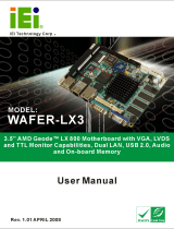
EPM-15 Block Diagrams
Figure 1. System Block Diagram
DDR
SDRAM
Address, Data, Control
SDCLKS
Analog RGB
Digital RGB
System Control
PCI, 3.3V
33 MHz
14.318 MHz
24.576 MHz
32.768 MHz
25.000 MHz
48.000 MHz
PWRBTN# (SOFT
PWR BUTTON)
ACPI DISABLE
JUMPER
PCI Connector
USB 2.0
(4 Ports)
RS-485/422
(2 Ports)
Connector
I/O Connector
Intel
10/100M
IDE
RS-232
CPLD
ISA Bridge
AMD
LX
CPU
AMD
CS5536
I/O Companion
Series
Terms
System
Clocking
(MK1491-09)
FP LVDS
National
DS90C383A
FS2 JTAG
Pads
Audio
Series
Terms
CompactFlash
Connector
BIOS
ISA Connector
ACPI Disable
PWR Control
PCI Arbitration
SMSC
LPC47N217
Super I/O

Introduction
EPM-15 Reference Manual 4
Figure 2. Power Control Block Diagram
SUSPEND TO RAM POWER
SYSTEM POWER ON
5.0V
1.2V_SB @ 1 mA
3.3V_SB @ 3 mA
2.5V_SB @ 1.5A
2.5V @ 1A
1.5V @ 2.3A
1.2V @ 200 mA
3.3V @ 1.4A
DDR VTT/REF
DDR VTT/REF2
CPU VMEM
CPU VCORE
CS5536 VCORE
CPU and CS5536 VIO
POR TO CS5536
CS5536 Standby
CS5536 & CPLD Standby
CS5536 Standby
EIRQ1_3V (EXTERNAL WAKE)
PWRBTN# (SOFT PWR BUTTON)
WORK_AUX
EN PWR
EN PWR#
LTC3412
LTC3412
LTC3412
I809
Si233DS MOSFET
RESISTOR DIVIDER
RESISTOR DIVIDER
LTC3025
PWR CONTROL
TPS79912
TPS79933

Introduction
EPM-15 Reference Manual 5
RoHS Compliance
The EPM-15 is RoHS-compliant.
ABOUT ROHS
In 2003, the European Union issued Directive 2002/95/EC regarding the Restriction of the use of
certain Hazardous Substances (RoHS) in electrical and electronic equipment.
The RoHS directive requires producers of electrical and electronic equipment to reduce to
acceptable levels the presence of six environmentally sensitive substances: lead, mercury,
cadmium, hexavalent chromium, and the presence of polybrominated biphenyls (PBB) and
polybrominated diphenyl ethers (PBDE) flame retardants, in certain electrical and electronic
products sold in the European Union (EU) beginning July 1, 2006.
VersaLogic Corporation is committed to supporting customers with high-quality products and
services meeting the European Union’s RoHS directive.
Warnings
ELECTROSTATIC DISCHARGE
Warning! Electrostatic discharge (ESD) can damage circuit boards, disk drives and other
components. The circuit board must only be handled at an ESD workstation. If an
approved station is not available, some measure of protection can be provided by
wearing a grounded antistatic wrist strap. Keep all plastic away from the board,
and do not slide the board over any surface.
After removing the board from its protective wrapper, place the board on a
grounded, static-free surface, component side up. Use an antistatic foam pad if
available.
The board should also be protected inside a closed metallic anti-static envelope
during shipment or storage.
Note: The exterior coating on some metallic antistatic bags is sufficiently conductive to
cause excessive battery drain if the bag comes in contact with the bottom-side of
the EPM-15.
LITHIUM BATTERY
Warning! To prevent shorting, premature failure or damage to the lithium battery, do not
place the board on a conductive surface such as metal, black conductive foam or
the outside surface of a metalized ESD protective pouch. The lithium battery may
explode if mistreated. Do not recharge, disassemble or dispose of in fire. Dispose
of used batteries promptly and in an environmentally suitable manner.

Introduction
EPM-15 Reference Manual 6
HANDLING CARE
Warning! Care must be taken when handling the board not to touch the exposed circuitry
with your fingers. Though it will not damage the circuitry, it is possible that small
amounts of oil or perspiration on the skin could have enough conductivity to cause
the contents of CMOS RAM to become corrupted through careless handling (such
as when changing the CompactFlash module), resulting in CMOS resetting to
factory defaults.

Introduction
EPM-15 Reference Manual 7
Technical Support
If you are unable to solve a problem after reading this manual please visit the EPM-15 Product
Support web page shown below. If you have further questions, contact VersaLogic technical
support at (541) 485-8575. VersaLogic technical support engineers are also available via e-mail
REPAIR SERVICE
If your product requires service, you must obtain a Returned Material Authorization (RMA)
number by calling (541) 485-8575.
Please provide the following information:
Your name, the name of your company, your phone number, and e-mail address
The name of a technician or engineer that can be contacted if any questions arise
Quantity of items being returned
The model and serial number (barcode) of each item
A detailed description of the problem
Steps you have taken to resolve or recreate the problem
The return shipping address
Warranty Repair All parts and labor charges are covered, including return shipping
charges for UPS Ground delivery to United States addresses.
Non-warranty Repair All non-warranty repairs are subject to diagnosis and labor charges,
parts charges and return shipping fees. Please specify the shipping
method you prefer and provide a purchase order number for invoicing
the repair.
Note: Please mark the RMA number clearly on the outside of the box before
returning.
EPM-15 Support Website
http://www.versalogic.com/private/manxsupport.asp

EPM-15 Reference Manual 8
Configuration and Setup
Initial Configuration
The following components are recommended for a typical development system.
EPM-15 Computer
ATX Power Supply
SVGA Video Monitor
Standard I/O Utility Cable (CBR-5010)
USB Keyboard
USB Floppy Disk Drive
IDE Hard Drive (optional)
IDE CD ROM Drive (optional)
The following VersaLogic cables are recommended.
CBR-1201 – Video adapter cable
CBR-5010 – Utility I/O cable (CBR-5009A) and breakout board (CBR-5010B)
CBR-4406 – IDE data cable
CBR-4405 – IDE adapter board, if you are using drives with 40-pin connectors
CBR-1008 – Power adapter cable
You will also need a Windows (or other OS) installation CD.
Basic Setup
The following steps outline the procedure for setting up a typical development system. The EPM-
15 should be handled at an ESD workstation or while wearing a grounded antistatic wrist strap.
Before you begin, unpack the EPM-15 and accessories. Verify that you received all the items you
ordered. Inspect the system visually for any damaged that may have occurred in shipping.
Contact [email protected] immediately if any items are damaged or missing.
Gather all the peripheral devices you plan to attach to the EPM-15 and their interface and power
cables.
It is recommended that you attach standoffs to the board (see Hardware Assembly) to stabilize
the board and make it easier to work with.
Figure 3 shows a typical start-up configuration (using RoHS compatible cables).
2 2

Configuration and Setup
EPM-15 Reference Manual 9
Figure 3. EPM-15 Typical Start-up Configuration
1. Attach Power
Plug the power adapter cable CBR-1008 into socket J9. Attach the motherboard
connector of the ATX power supply to the adapter.
2. Attach Cables and Peripherals
Plug the video adapter cable CBR-1201 into socket J1. Attach the video monitor
interface cable to the video adapter.
Plug the breakout cable CBR-5009A into socket J8. If necessary, attach the breakout
board CBR-5010B to the cable. (The cable and board are shipped attached.)
Plug a USB keyboard and USB floppy drive into socket J4 of the breakout board.
Plug the hard drive data cable CBR-4406 into socket J7. Attach a hard drive and CD-
ROM drive to the connectors on the cable. If the hard drive is 3.5”, use the 2mm to 0.1”
adapter CBR-4405 to attach the IDE cable.
Attach an ATX power cable to any 3.5” drive (hard drive or CD-ROM drive).
OS Installation
CD-ROM
Hard
Drive
CD-ROM
Drive
CBR –5010B
J4
J1
CBR–1008
USB Keyboard
and USB Mouse
Power
to
Drives
Analog SVGA
CBR–1201
J1
J9
J7
J8
EPM-15
“Manx”
CBR –5009A
CBR–4406
ATX
Power Supply

Configuration and Setup
EPM-15 Reference Manual 10
Set the hard drive jumper for master device operation and the CD-ROM drive jumper for
slave device operation.
3. Review Configuration
Before you power up the system, double check all the connections. Make sure all cables
are oriented correctly and that adequate power will be supplied to the EPM-15 and
peripheral devices.
4. Power On
Turn on the ATX power supply and the video monitor. If the system is correctly
configured, a video signal should be present.
5. Change CMOS Setup Settings
Enter CMOS Setup by pressing Delete during the early boot cycle.
Select Basic Configuration and set or verify the following settings:
DRIVE ASSIGNMENT ORDER | Drive C: Ide 0/Pri Master
ATA DRV ASSIGNMENT | Ide 0: 3 = AUTOCONFIG, LBA
ATA DRV ASSIGNMENT | Ide 1: 5 = IDE CDROM
BOOT ORDER | Boot 1st: CDROM
BOOT ORDER | Boot 2nd: Drive C:
Before saving the CMOS Setup settings, insert the Windows (or other OS) installation
disk in the CD-ROM drive so it will be accessed when the system reboots.
Press ESC and select the option to save the new parameters to CMOS RAM. The system
will reboot.
6. Install Operating System
Install the operating system according to the instructions provided by the OS
manufacturer. (See Operating System Installation.)
Note: If you intend to operate the EPM-15 under Windows XP or Windows XP
Embedded, be sure to use Service Pack 2 (SP2) for full support of the latest CS5536 I/O
hub and its USB 2.0 features.

Configuration and Setup
EPM-15 Reference Manual 11
CMOS Setup
The default CMOS Setup parameters for the EPM-15 are shown below.
Basic CMOS Configuration
+------------------------------------------------------------------------------+
| System BIOS Setup - Basic CMOS Configuration |
| (C) 2005 General Software, Inc. All rights reserved |
+---------------------------+--------------------+-----------------------------+
| DRIVE ASSIGNMENT ORDER: | Date:>Apr 09, 2009 | Typematic Delay : 250 ms |
| Drive A: (None) | Time: 00 : 00 : 00 | Typematic Rate : 30 cps |
| Drive B: (None) | NumLock: Disabled | Seek at Boot : None |
| Drive C: Ide 0/Pri Master +--------------------+ Show "Hit Del" : Enabled |
| Drive D: (None) | BOOT ORDER: | Config Box : Enabled |
| Drive E: (None) | Boot 1st: Drive C: | F1 Error Wait : Enabled |
| Drive F: (None) | Boot 2nd: (None) | Parity Checking : (Unused) |
| Drive G: (None) | Boot 3rd: (None) | Memory Test Tick : Enabled |
| Drive H: (None) | Boot 4th: (None) | Debug Breakpoints: (Unused) |
| Drive I: (None) | Boot 5th: (None) | Debugger Hex Case: Upper |
| Drive J: (None) | Boot 6th: (None) | Memory Test : StdLo FastHi |
| Drive K: (None) +--------------------+-----------------+-----------+
| Boot Method: Boot Sector | ATA DRV ASSIGNMENT: Sect Hds Cyls | Memory |
+---------------------------+ Ide 0: 3 = AUTOCONFIG, LBA | Base: |
| FLOPPY DRIVE TYPES: | Ide 1: 3 = AUTOCONFIG, LBA | 632KB |
| Floppy 0: Not installed | Ide 2: Not installed | Ext: |
| Floppy 1: Not installed | Ide 3: Not installed | 219MB |
+---------------------------+--------------------------------------+-----------+
Features Configuration
+------------------------------------------------------------------------------+
| System BIOS Setup - Features Configuration |
| (C) 2005 General Software, Inc. All rights reserved |
+---------------------------------------+--------------------------------------+
| ACPI 1.0 :>Enabled | System Management Mode : Enabled |
| POST Memory Manager : Disabled | Splash Screen : Disabled |
| System Management BIOS : Enabled | Primary IDE UDMA : Enabled |
| Console Redirection : Auto | Firmbase Debug Console : None |
| UsbMassStorage : Enabled | Usb20 : Enabled |
+---------------------------------------+--------------------------------------+
Custom Configuration
+------------------------------------------------------------------------------+
| System BIOS Setup - Custom Configuration |
| (C) 2005 General Software, Inc. All rights reserved |
+---------------------------------------+--------------------------------------+
| PCI INT A Assignment :>IRQ 11 | ISA IRQ 3 : Disabled |
| PCI INT B Assignment : IRQ 11 | ISA IRQ 4 : Disabled |
| PCI INT C Assignment : IRQ 11 | ISA IRQ 10 : Disabled |
| PCI INT D Assignment : IRQ 9 | Reserved : Reserved |
| Write protect BIOS : Enabled | Reserved : Reserved |
| Video buffer size : 32 MB | LPT1 (378) Enable/IRQ : No IRQ |
| Flat panel display : Disabled | Parallel Port Mode : Printer |
| Video refresh rate : 60 Hz | COM1 (3F8) RS-232 : IRQ4 |
| Video data width : 1 pix/clk | COM3 (3E8) RS-422/485 : Disabled |
| Primary video device : Auto | COM4 (2E8) RS-422/485 : Disabled |
| Memory timings : Optimal | Reserved : Reserved |
| CPU Temp threshold : 80*C | BIOS extension : Disabled |
| CPU overtemp IRQ : Disabled | Legacy USB support : Enabled |
| CPU/Memory speeds : 500/333 MHz | IDE cable type : 40-Wire |
| Periodic SMM IRQ : Enabled | |
+---------------------------------------+--------------------------------------+

Configuration and Setup
EPM-15 Reference Manual 12
Shadow Configuration
+------------------------------------------------------------------------------+
| System BIOS Setup - Shadow/Cache Configuration |
| (C) 2005 General Software, Inc. All rights reserved |
+---------------------------------------+--------------------------------------+
| Shadowing :>Chipset | Shadow 16KB ROM at C000 : Enabled |
| Shadow 16KB ROM at C400 : Enabled | Shadow 16KB ROM at C800 : Disabled |
| Shadow 16KB ROM at CC00 : Disabled | Shadow 16KB ROM at D000 : Disabled |
| Shadow 16KB ROM at D400 : Disabled | Shadow 16KB ROM at D800 : Disabled |
| Shadow 16KB ROM at DC00 : Enabled | Shadow 16KB ROM at E000 : Enabled |
| Shadow 16KB ROM at E400 : Enabled | Shadow 16KB ROM at E800 : Enabled |
| Shadow 16KB ROM at EC00 : Enabled | Shadow 64KB ROM at F000 : Enabled |
+---------------------------------------+--------------------------------------+
Note: Due to changes and improvements in the system BIOS, the information on your
monitor may differ from that shown above.
Operating System Installation
The standard PC architecture used on the EPM-15 makes the installation and use of most of the
standard x86 processor-based operating systems very simple. The operating systems listed on the
VersaLogic OS Compatibility Chart use the standard installation procedures provided by the
maker of the OS. Special optimized hardware drivers for a particular operating system, or a link
to the drivers, are available at the EPM-15 Product Support web page at
http://www.versalogic.com/private/manxsupport.asp.

EPM-15 Reference Manual 13
Physical Details
Dimensions
EPM-15 DIMENSIONS AND MOUNTING HOLES
The EPM-15 complies with all PC/104-Plus standards. Dimensions are given below to help with
pre-production planning and layout. All dimensions are in inches. Drawings are not to scale.
Figure 4. EPM-15 Dimensions
3 3
0.200
3.175
3.375
3.275
0.100
0.000
0.150
3.050
3.700
–0.550
–0.200
0.000
3.150
3.350
3.575
-0.200

Physical Details
EPM-15 Reference Manual 14
CBR-5010 DIMENSIONS AND MOUNTING HOLES
Figure 5. CBR-5010 Dimensions
1.95
1.575
1.875
1.38
0.065
5.50
5.10
1.175
/