Page is loading ...

DIGITAL HiNote
VP 700 Series
Service Quick Reference Guide
Part Number: ER-PJ1WW-SR. A01
Digital Equipment Corporation

December 1997
The information in this document is subject to change without
notice and should not be construed as a commitment by Digital
Equipment Corporation.
Digital Equipment Corporation assumes no responsibility for any
errors that might appear in this document.
The software described in this document is furnished under a
license and may be used or copied only in accordance with the
terms of such license. No responsibility is assumed for the use
or reliability of software or equipment that is not supplied by
Digital Equipment Corporation or its affiliated companies.
Restricted Rights: Use, duplication, or disclosure by the U.S.
Government is subject to restrictions as set forth in
subparagraph (c) (1) (ii) of the Rights in Technical Data and
Computer Software clause at DFARS 252.227-7013.
DIGITAL HiNote VP 700 Series Service
Quick Reference Guide
Copyright © Digital Equipment Corporation.
All Rights Reserved.
DEC, DIGITAL, ThinWire, and the DIGITAL logo are registered
trademarks of Digital Equipment Corporation
Intel and Pentium are registered trademarks of Intel Corporation
Microsoft, MS-DOS, and Windows are registered trademarks of
Microsoft Corporation.
All other trademarks and registered trademarks are the property
of their respective holders.

FCC Notice
This equipment has been tested and found to comply with the
limits for a Class B digital device, pursuant to Part 15 of the FCC
rules. These limits are designed to provide reasonable
protection against harmful interference in a residential
installation.
Any changes or modifications made to this equipment may void
the user's authority to operate this equipment.
This equipment generates, uses, and can radiate radio
frequency energy and, if not installed and used in accordance
with the instructions, may cause harmful interference to radio
communications. However, there is no guarantee that
interference will not occur in a particular installation. If this
equipment does cause harmful interference to radio or television
reception, which can be determined by turning the equipment off
and on, the user is encouraged to try to correct the interference
by one or more of the following measures:
• Reorient or relocate the receiving antenna
• Increase the separation between the equipment and
receiver
• Connect the equipment into an outlet on a circuit
different from that to which the receiver is connected
• Consult the dealer or an experienced radio/TV
technician for help
All external cables connecting to this basic unit need to be
shielded. For cables connecting to PCMCIA cards, see the
option manual or installation instructions.

i
Contents
Preface..............................................................................................................v
1
Overview
Introduction.................................................................................................1-1
System Overview.......................................................................................1-1
CPU.............................................................................................................1-1
Chip Set ......................................................................................................1-2
Memory.......................................................................................................1-3
BIOS............................................................................................................1-4
PCI Bus Devices........................................................................................1-4
Cardbus Controller ................................................................................1-4
Video Controller Chip............................................................................1-5
ISA Bus Devices ........................................................................................1-6
Audio.......................................................................................................1-6
Wavetable (Optional).............................................................................1-6
BIOS.......................................................................................................1-7
Super I/O................................................................................................1-7
Components, Controls and Indicators......................................................1-8
Front and Side Components (Panel Closed)......................................1-8
Rear View.............................................................................................1-10
Left Side Components.........................................................................1-12
Right Front View (Panel Open) ..........................................................1-14
Controlling Power.....................................................................................1-16
LCD Status Display..................................................................................1-17
Battery Charge Gauge (in LCD Status Display)....................................1-18

Contents
ii
Keyboard Hot Keys (US Keyboard)........................................................1-19
General Battery Information ....................................................................1-21
Nickel Metal Hydride Battery Care..........................................................1-21
Memory Effect......................................................................................1-21
NiMH Battery Life............................................................................1-21
Forming a Battery.....................................................................................1-22
LiIon Battery..............................................................................................1-23
Smart Battery Operation..........................................................................1-25
Power Management Modes....................................................................1-25
Standby Mode......................................................................................1-26
Suspend Mode ....................................................................................1-26
Save to Disk Mode..............................................................................1-28
Related Information..................................................................................1-29
Documentation.....................................................................................1-29
World Wide Web .................................................................................1-29
2
System Restoration
Introduction.................................................................................................2-1
Reinstalling and Installing Drivers.............................................................2-1
Reinstalling Drivers................................................................................2-1
Installing Drivers.....................................................................................2-2
Creating a Bootable Floppy.......................................................................2-3
Windows 95 System Restoration..............................................................2-4
Re-installing Windows 95..........................................................................2-5
System Restoration Using Existing Partitions..........................................2-6
Complete System Restoration..................................................................2-7
RAM Increase Over 80MB Total...............................................................2-9
Windows NT 4.0 System Restoration ....................................................2-10
Creating an Emergency Repair Disk......................................................2-10
System Recovery Using an Emergency Repair Disk ...........................2-11
Windows NT 4.0 System Restoration ....................................................2-12
NTFS Conversion................................................................................2-13
Creating a Save-to-File (FAT16 Only—Non NTFS).........................2-14
3
System BIOS
Introduction.................................................................................................3-1
BIOS Setup Program.................................................................................3-1
Navigating through the Setup Program....................................................3-2

Contents
iii
Accessing the Setup Program ..................................................................3-3
Menu Bar................................................................................................3-4
Item Specific Help..................................................................................3-4
Legend Bar.............................................................................................3-5
Launching Submenus................................................................................3-6
General Help...............................................................................................3-6
The Main Menu ..........................................................................................3-7
The Hard Disk Submenu......................................................................3-9
The System Devices Menu.....................................................................3-10
The Security Menu...................................................................................3-16
Setting System Password...................................................................3-18
Changing System Password..............................................................3-18
Deleting System Password.................................................................3-18
The Power Menu......................................................................................3-19
The Boot Menu.........................................................................................3-23
The Exit Menu ..........................................................................................3-24
4
Troubleshooting
Introduction.................................................................................................4-1
Troubleshooting Tips..................................................................................4-2
System Start Failure..............................................................................4-3
Power Supply Failure............................................................................4-4
Boot-up Failure ......................................................................................4-6
Post Failure............................................................................................4-7
LCD Panel Failure.................................................................................4-8
CRT Failure............................................................................................4-9
Notebook Computer Keyboard Failure..............................................4-10
External Keyboard or PS/2 Mouse Failure........................................4-11
HDD Failure.........................................................................................4-12
FDD Failure..........................................................................................4-13
CD-ROM Failure..................................................................................4-13
Battery Failure......................................................................................4-14
Check Points and Error Messages.........................................................4-15
Phoenix BIOS Test Points.......................................................................4-16

Contents
iv
5
FRU Replacement
Introduction.................................................................................................5-1
Required Tools...........................................................................................5-2
Removing the Battery Pack.......................................................................5-6
Removing the 20x CD/FDD Combination Module and
Supplementary Battery............................................................................5-8
Removing the HDD Assembly................................................................5-10
Removing Memory Modules (DIMMs) ...................................................5-12
Removing the Speaker Cover.................................................................5-16
Removing the Keyboard..........................................................................5-18
Removing the LCD Assembly.................................................................5-20
Shell Installation Instructions...................................................................5-24
Prior to Disassembly ...........................................................................5-25
Disassembly Instructions....................................................................5-25
A
Specifications
Base Unit.....................................................................................................A-1
Ports............................................................................................................A-3
Audio...........................................................................................................A-4
LCD Display................................................................................................A-5
PCMCIA (PCI)............................................................................................A-6
BIOS Support .............................................................................................A-6
Power..........................................................................................................A-7
Battery, Status Display, Keyboard............................................................A-8
Physical.......................................................................................................A-8
B
Device Mapping
Memory Map...............................................................................................B-1
DMA Channel Assignments......................................................................B-2
Notebook Computer Interrupt Levels........................................................B-3
I/O Address Map ........................................................................................B-4

Contents
v

v
Preface P
This Service Quick Reference Guide describes how to test,
troubleshoot, and remove and replace the DIGITAL HiNote VP
700 Series notebook computer Field Replaceable Units (FRUs).
This guide is written specifically for DIGITAL approved on-site
service engineers. On-site repair of systems beyond the
approved FRU list is prohibited and may void warranty.
CAUTION: DIGITAL recommends that only A+
certified engineers attempt to repair this
equipment. All troubleshooting and repair
procedures are detailed to support
subassembly/module level exchange. Because
of the complexity of the individual boards and
subassemblies, no one should attempt to make
repairs at the component level or make
modifications to any printed circuit board.
Improper repairs can create a safety hazard.
Any indications of component replacement or
circuit board modifications might void any
warranty or exchange allowances.

Preface
vi

1-1
1
Overview 1
Introduction
This chapter introduces the DIGITAL HiNote VP 700 series
notebook computer. It provides a system overview and
describes the controls, indicators, and hot keys.
System Overview
The DIGITAL HiNote VP 700 series notebook computer is a
high-performance portable computer designed for the mobile
professional.
CPU
The DIGITAL HiNote VP 700 series notebook computer
supports the notebook version of the P55C 166MHz and beyond
Intel Pentium processors mounted on an MMO daughter card.
The following is a list of the general features of these processors:
• Low power consumption operating at 1.8V.
• Full System Management Interrupt (SMI) support.

Overview
1-2
• Fully static - support Stop Grant and Stop Clock states.
• 32-bit address bus.
• 64-bit data bus.
• 32KB internal write-back cache (L1).
• Capable of executing two instructions per clock cycle
using two pipelined integer units.
• Multimedia extension (MMX) register set.
Chip Set
The Intel 430TX PCI chip set is used to implement the core
functions of the system.
• The 430TX System Controller, 82439TX, provides core
system functions.
− Support for all Intel Pentium processors since
P54C.
− Integrated L2 Cache Controller featuring support
for Write-Back cache policy for cache sizes 256KB
and 512KB, DIRECT Mapped Organization (Write-
Back only), Cache Hit Read/Write cycle timings @
3-1-1-1, and back-to-back Read/Write cycles @ 3-
1-1-1-1-1-1-1.
− Fully synchronous, Minimum Latency 30/33MHz
PCI bus interface supporting five PCI bus Masters,
a 10 Dword PCI-to-DRAM Read Prefetch buffer,
an 18 Dword PCI-to-DRAM Post Buffer, and a
Multiple Transaction timer to support multiple short
PCI transactions.

Overview
1-3
− 64-bit host and DRAM bus interface with an
integrated DRAM controller with 64Mbit
DRAM/SDRAM Technology and programmable-
strength for DRAM interface.
− Integrated PCI bus arbiter.
− Advanced Power Management features.
− Support for USB.
• The PCI ISA IDE Xcelerator, PIIX4, provides the PCI to
ISA bridge interface.
− Integrated IDE Controller supporting up to 4 drives,
PIO Mode 4 transfers up to 14Mbytes per second,
and integrated 8x32 buffers for IDE PCI Burst
transfers.
− Enhanced DMA Controller supporting two 8237
DMA controllers supporting PCI DMA with
3PC/PCI channels and Distributed DMA protocols.
− Interrupt Controller with support for 15 interrupts
and independently programmable for Edge/Level
sensitivity.
− Support for full Positive Decode or Subtractive
Decode.
− Advanced Power Management features.
− Support for two USB ports for serial transfers at
12Mbit/s or 1.5Mbit/s.
Memory
The system comes with 16MB of on-board SDRAM for system
memory and 256KB or 512KB of L2 cache memory depending
on the model purchased.

Overview
1-4
System memory can be upgraded to a total of 144MB. The
upgrade is performed by installing any combination of 16MB,
32MB and 64MB SDRAM SO-DIMMs. There are two slots for
additional memory. Memory can be upgraded one module at a
time. Either slot can be populated first.

Overview
1-5
BIOS
The system has a 256KB Flash ROM for system BIOS (Phoenix
BIOS 4.0 Release 6). BIOS provides support for the following:
• Suspend to RAM.
• Save to Disk
• Full APM 1.2 supported.
• Password protection (Boot and System options).
• Auto-configured with module and docking options.
• Windows 95 ready with PnP.
• 32KB ROM for 51SL keyboard controller.
• Gas-gauge for battery status information
• Various hot-keys for system control.
PCI Bus Devices
The internal PCI bus and PCI components operate at 3.3V. The
PCI bus is also available to supported docking options.
Cardbus Controller
Cardbus support is provided by the TI1131 controller. This chip
provides the following functions:
• Support for Zoomed Video.
• Support for two PC Card/Cardbus slots with hot
removal/insertion.
• Uses burst transfers to maximize data throughput on
the PCI/Cardbus bus.
• Support for serialized ISA IRQs.
• Support for 16-bit distributed DMA.

Overview
1-6
• Support for Ring Indicate.
Video Controller Chip
Video support is provided by theNeo Magic 2160 Controller
Chip. This chip provides the following functions:
• 128-bit memory interface.
• 2MB 3.3V High Speed Video DRAM.
• Support for Zoomed Video.
• Simultaneous display supported.
• VESA DDC1 support for external monitors.
• Advanced power management features minimize power
consumption during:
− Normal operation
− Standby mode
− Panel-off
• High resolution panel:
− TFT displays support XGA (1024x768) at a
maximum of 64K colors.
− DSTN displays support XGA (1024x768) at a
maximum of 64K colors.

Overview
1-7
ISA Bus Devices
The ISA bus interface is provided by the Intel 430TX PCIset
System Controller.
Audio
Audio support is provided by the Crystal CS4237B chip. This
chip provides the following functions:
• Integrated SRS 3D sound technology
• Enhanced full-duplex operation.
• Dual Type-F DMA support.
• Advanced MPC3-Compliant input/output mixer.
• Hardware master volume control
• Advanced Power Management..
• Support for 16-bit Stereo, FM Synthesizer, and MPU-
401 MIDI.
• Enhanced digital gameport.
Wavetable (Optional)
Wavetable support is provided by the Crystal CS9236 chip. This
chip provides the following functions:
• High quality MIDI sample set including 128 melodic
instruments and 47 percussion sounds.
• Receives standard serial MIDI data stream and outputs
stereo 16-bit digital audio stream at 44.1kHz.
• Independent reverb and chorus levels for each MIDI
channel.
• General MIDI (GM) compliant.

Overview
1-8
• Fully static power down capability.
BIOS
The system BIOS is implemented using the Intel 28F002BX-T
2MB Boot block Flash ROM.
Super I/O
I/O support is provided by theSMC EDC37C669FR chip. This
chip supports the following functions:
• 2.38MB Super I/O Floppy Disk controller supporting two
floppy drives and offering Japanese floppy support.
• Floppy Disk available on Parallel port pins.
• Two high speed NS 160550 compatible UARTs Serial
Ports.
• Integrated Infrared Communications controller
supporting SIR (115Kbps) and FIR (4Mbps) data
transfers.
• Multi-Mode Parallel Port – IEEE 1284 compliant.
• Full Plug-and-Play support.
• Game Port Select Logic

Overview
1-9
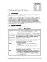
Components, Controls and Indicators
This section shows the locations and provides detailed
description of the different components, controls, and indicators
on your DIGITAL HiNote VP 700 Series notebook computer.
Front and Side Components (Panel Closed)
Component Description
➊Lid Release Slide this latch to the right to open the
LCD panel.
➋Main Battery Module Removable battery module that can be
replaced with a charged battery.
➌Expansion bay Supports the 20X CD-ROM/FDD
Combination module and optional
lithium-ion secondary battery module.
➍Minidock Locking Tab Used to secure the notebook to the
Minidock.
➎Power/Charge LED Indicates the power and charge status
of notebook.
System plugged into AC Power
• LED solid, battery is charging.
• LED blinking (fast), battery
not charging.
System running on Battery Power
• LED blinking (slow), notebook is
in suspend.

Overview
1-10
DEC01350
Figure 1-1: Right Front View (Panel Closed)
/