Page is loading ...

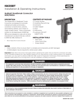
Hubbell Deadbreak Connector
600/900A
IS628BT
Installation & Operating Instructions
IS628BT Rev. D 04/23
Important: Read these instructions thoroughly before operating the system. Be sure that the connectors are rated
for the intended energized use. (See Hubbell catalog (C7) for selecting the correct mating product.) For additional
information, you may want to reference IEEE Std. 1816, Guide for Preparation Techniques of Extruded Dielectric,
Shielded Cables Rated 2.5 kV through 46 kV and the Installation of Mating Accessories.
! DANGER
The equipment covered by these instructions should be installed, operated and serviced only by competent personnel
familiar with safety practices. This instruction is written for such personnel and is not intended as a substitute for adequate
training and experience in safe procedures for this type of equipment.
Optional Capacitive Test Point- When making voltage measurements, the area of and around the voltage test point must
be dry and free of contaminants. The voltage test point is not intended for actual voltage measurements or phasing
operations and has no direct connection to the conductor. It uses an impedance capacitance tap and only voltage
indicating instruments designed for this application to establish the presence of voltage should be used. A voltage
reading will indicate the presence of voltage, but a reading of no voltage is not sucient to establish a de-energized
circuit before touching the connector. Other procedures should be implemented to establish a de-energized circuit.
Do not touch or move energized product by hand. Failure to follow this instruction may result in serious or fatal injury, as
well as damage to the product.
! WARNING
These instructions do not purport to cover all details or variations in equipment nor to provide for every possible contingency to be
met in connection with installation, operation or maintenance. Should further information be desired or should particular problems
arise which are not covered suciently for the purchaser’s purposes, the matter should be referred to Hubbell Power Systems, Inc.
hubbellpowersystems.com
DESCRIPTION
The Hubbell 600 A Deadbreak T-body
Connectors are designed to terminate
underground cables and provide a
connection to transformers, switches,
sectionalizing cabinets, and a means to
create modular splices. These components
conform to all requirements of IEEE Std.
386 and are designed to mate with all other
manufacturer’s products that also conform
to IEEE Std. 386, Interface 11.
• 15/25 kV Class 15.2 kV
NOTES
• Check contents of box to ensure that it is complete and components are NOT damaged.
• A shield adaptor may be required for certain power cables.
CONTENTS OF PACKAGE
(1) T-body Housing
(1) Insulating Plug with Cap
(1) Connector
(1) Cable Adapter
(1) Stud
(1) Instructions
(1) Lubricant (DO NOT
SUBSTITUTE)
INSTALLATION TOOLS
• Torque Wrench
• Crimp Tools & Dies
• Hand Tools
! DANGER

CABLE PREPARATION
NOTE: These instructions will cover concentric neutral cable
applications so please refer to cutback instructions from
shield adapter kits for steps on how to prepare other types of
underground power cables.
Step 1 – Train & Remove Jacket
A. Train the cable into the final assembled position using
the natural bending of the cable. Allow sucient slack
in the cable to move the T-body at least a foot from the
apparatus bushing.
B. To provide sucient length of concentric neutral
conductor for grounding after installation, measure
14 3/4”” down the cable from the centerline of the
bushing interface and remove the jacket to this distance.
Care should be taken not to damage neutral wires. (See
Figure 1.)
C. Bend neutral wires out of the way.
(See Figure 2.)
Step 2 – Cable Preparation
A. Cut the excess cable o square and 1-3/4” below the
centerline of the bushing. (See Figure 3.)
B. Remove insulation to expose bare conductor. Cut squarely
making sure not to cut or nick the conductor.
Compression lugs - “X” = 4 1/2”
Shear Bolt lugs - “X” = Depth of Lug
(See Figure 4.)
C. Remove the insulation shield 9-3/4” back from the end
of the cable. Cut squarely, making sure not to nick or
damage the insulation.
D. Apply two layers of vinyl tape onto the insulation shield
10-3/4” back from the end of the cable. This will serve as
a temporary marker for locating the cable adapter. (See
Figure 5.)
E. Bevel the insulation end 1/8” max.
Thoroughly clean the insulation.
IS628BT Rev. D 04/23
10 3/4”
Extruded
Insulation Shield
9 3/4”
Cable Insulation
Tape Marker
Fig. 5 - Shield Cutback
Tape Marker
Fig. 3 - Cable Train Dimensions
cable
1 3/4” 600 Amp
bushing
Fig. 1 - Cable Train &
Outer Jacket Removal
Fig. 2 - Concentric
Neutral Preparation
Outer
Jacket
Outer
Jacket Pigtail
600 Amp
bushing
600 Amp
bushing
14 3/4” 14 3/4”
Drain Wires
Fig. 4 - Insulation Cut Back
Tape Marker
“X”
BEVEL 1/8” MAX
“13”

INSTALLATION
NOTE: The end of the jacket should be sealed to prevent
water ingression into the housing. It is recommended to use
commercially available products to reconstruct the cable
jacket.
Step 3 - Cable Adapter Installation
A. Apply a thin, uniform coating of the supplied lubricant to
the bore of the cable adapter and the cable insulation.
DO NOT SUBSTITUTE as other lubricants may be
harmful to products
B. Slide cable adapter onto cable until it is flush with the
tape marker. (See Figure 6.)
Step 4 - Connector Installation
A. Use a wire brush to clean the exposed conductor and
immediately install the connector. Rotate the connector
to spread the inhibitor.
1. Compression Connectors
a. Verify check dimension is less than 6 1/2” prior
to crimping. (See figure 7) Refer to crimp chart
packed with connector.
b. Measure check dimension after crimping to verify
it is between 6 1/2” and 7 1/4”. ( See Figure 8)
2. Shear Bolt Connectors
a. Refer to installation instructions packed with
Shear Bolt connector.
Note: Ensure connector will sit flat against the face of
the equipment bushing before crimping or shearing
Step 5 - T-Body Installation
A. Clean and lubricate the cable entrance of the T-Body
and the outside of the cable adapter with supplied
lubricant. (See Figure 9.)
B. While holding the cable adapter in place and making
sure the connector is properly aligned. slide the T-Body
housing onto the cable assembly. The housing should
bottom out onto the connector. Verify that the cable
adapter did not move and is still flush with the tape
marker. If the adapter moves, pull it back up a few
inches, reapply silicone lubricant to the cable insulation,
and reposition until it is again flush with the tap marker.
(see Figure 10.)
C. Remove tape marker.
IS628BT Rev. D 04/23
Fig. 6 - Install Cable Adapter
tape Cable Adapter
edge
Fig. 7 - Check & Crimp
Cable Adapter
Check Dimension
Compression Lug
Fig. 8 - Final Crimp Dimensions
on this end
6 1/2” - 7 1/4”
After Crimping
Cable Adapter
Locate First Crimp
Compression Lug
Tape marker
Lubricate
Cable Adapter
Fig. 9 - Clean & Lubricate
Tape marker
Slide this direction
Cable Adapter
Flush

CONNECTION
NOTE: For kits with reducing taps or modular splice kits, please refer to
supplemental instructions packaged with those components.
Step 6 – Connection
A. Clean and lubricate the T-Body, apparatus
bushing, and insulating plug interfaces with
supplied lubricant.
B. Hand tighten the loose stud into the insulating
plug two or three turns if the mating interface
is not equipped with one.
C. Align the T-Body to the apparatus bushing
interface. Insert the insulating bushing and
hand tighten to prevent cross-threading.
Tighten the insulating bushing to 50-60 ft-
lbs of torque using a 1” socket and a torque
wrench. (See Figure 11.)
D. Clean and lubricate the test point cap and
snap it onto the insulating bushing.
Step 7 – Grounding
A. Attach a #14 AWG copper wire (or equivalent)
to the grounding eye of the T-body. Twist the
wire at least two turns to ensure it is secured
properly. Attach the free end to system
ground.
B. Twist the neutral wires into a braid and
connect to system ground with appropriate
connector. Make sure to provide sucient
slack in ground braid to provide for future
operation. (See Figure 12.)
©2023 Hubbell Incorporated.
Because Hubbell has a policy of continuous product improvement,
we reserve the right to change design and specifications without notice.
Printed in the U.S.A. | TD_03_048E
1850 Richland Ave. East • Aiken, SC 29801 | Phone: 573-682-5521
Fax: 573-682-8714 | E-mail: hpsliter[email protected]
hubbellpowersystems.com
IS628BT Rev. D 04/23
Fig. 11 - Assembly to Bushing Well
Fig. 12 - Final Steps
Insulating
Plug
Insulating
Plug Cap
Static
Drain Wire Concentric
Neutral Wires
600 Amp
Bushing
/