Page is loading ...

1
L-A2-222
REV 7 - 1305221425
Owner’s
Manual
Robert H. Peterson Co. • 14724 East Proctor Avenue • City of Industry, CA 91746
Standard Burner Systems:
G45-2-**(P)A
G45-2-**-01(M)(P)
G45-2-**-11(M)(P)
G45-2-**-15(M)(P)
G45-2-**-17(M)(P)
**Sizes:
(16/19, 18/20, 24, 30, 36)
For indoor stainless steel models;
add (-SS) to end of model #
The Real-Fyre gas log set is to be installed only in a
solid-fuel burning fi replace with a working fl ue and
constructed of noncombustible material. The installation,
including provisions for combustion and ventilation air
must conform with the National Fuel Gas Code, ANSI
Z223.1/NFPA 54, or the CSA B149.1, Natural Gas
and Propane Installation Code, and applicable local
building codes.
A damper clamp is included to maintain the minimum
permanent vent opening and to prevent full closure of
the damper blade. The chimney damper MUST be
fully opened when burning the log set. The log set is
designed to burn with yellow fl ames; thus adequate
ventilation is absolutely necessary.
To comply with certification, listings, and building
code acceptances, and for safe operation and proper
performance of this log set, use ONLY Peterson
parts and accessories. Use of other controls, parts,
and accessories that are not designed for use with
Real-Fyre gas log sets is prohibited and will void all
warranties, certifi cations, listings, and building code
approvals, and may cause property damage, personal
injury, or loss of life.
*Note: Solid-fuels shall not be burned in a fi replace
where a decorative appliance is installed.
IMPORTANT: READ THESE INSTRUCTIONS
CAREFULLY BEFORE STARTING
INSTALLATION OF THE LOG SET
Do not store or use gasoline or other
flammable vapors and liquids in the
vicinity of this or any other appliance.
WHAT TO DO IF YOU SMELL GAS:
• Open a window.
• Do not try to light any appliance.
• Do not touch any electrical switch; do
not use any phone in the building.
• Immediately call the gas supplier
from a neighbor’s phone. Follow gas
supplier’s instructions.
• If you cannot reach the gas supplier,
call the fi re department.
WARNING
If the information in this manual is not
followed exactly, a fi re or explosion may
result, causing property damage, personal
injury, or loss of life.
This appliance is only for use with the
type of gas indicated on the rating plate.
Installation and service must be
performed by a qualifi ed professional
installer, service agency, or the gas
supplier.
INSTALLER:
Leave this manual with the appliance.
CONSUMER:
Retain this manual for future reference.
G45-2 SERIES VENTED GAS LOG SETS (REGULATED)
FOR INSTALLATION IN
SEE-THRU SOLID-FUEL
BURNING FIREPLACES*
DESIGN CERTIFIED
to
Vented Decorative Appliance
ANSI Z21.60-2012
CSA 2.26-2012
11-020

3
L-A2-222
REV 7 - 1305221425
TABLE OF CONTENTS
4 NOTES PAGE
5 GENERAL INFORMATION
5 FIREPLACE SIZE REQUIREMENTS
6 REPLACEMENT BURNER PARTS LIST
7 SAFETY CONTROL SYSTEM FOR MANUAL SERIES
7 SAFETY CONTROL SYSTEM FOR 17 SERIES
8 SAFETY CONTROL SYSTEM FOR 11 SERIES
9 SAFETY CONTROL SYSTEM FOR 01 SERIES
9 SAFETY CONTROL SYSTEM FOR 15 SERIES
11 IMPORTANT PRE-INSTALLATION AND FIREPLACE SAFETY INFORMATION
12 INSTALLATION
12 INSTALLING THE BURNER
13 GRANULE, EMBER, AND GRATE PLACEMENT
14 01 VALVE MODELS ONLY
14 CONNECTING THE IGNITION PACK TO THE VALVE
14 INSTALLING OR REPLACING BATTERIES FOR IGNITION MODULE PACK
14 SWITCH BOX PLACEMENT
15 LOG PLACEMENT
17 LIGHTING INSTRUCTIONS - MANUAL PILOT AND SERIES 17 VALVE
19 LIGHTING INSTRUCTIONS - SERIES 15 VALVE
21 LIGHTING INSTRUCTIONS - SERIES 11 VALVE
23 LIGHTING INSTRUCTIONS - SERIES 01 VALVE
24 TROUBLESHOOTING
25 FLAME DESCRIPTION
26 WARRANTY

4
L-A2-222
REV 7 - 1305221425
NOTES PAGE
Please use this page to record any information about your unit that you may want to have at hand.

5
L-A2-222
REV 7 - 1305221425
The Real-Fyre
®
gas log set is to be installed only in a
fully vented, noncombustible fi replace with an open
damper. The chimney must be free of any obstructions.
The fi replace must be designed and approved to burn
wood.
The fi replace must have a gas supply line that has
been installed by a qualifi ed technician in accordance
with all local codes.
Be sure to clean the fi replace fl oor of any ashes or
other foreign materials. It is recommended that the
fi replace and chimney be inspected by a chimney
sweep or other qualifi ed person before you install the
Real-Fyre
®
gas log set.
Required Gas Pressure: The minimum inlet gas
supply pressure for the purpose of input adjustment
is 5" water column (w.c.) for natural gas and 11"
w.c. for propane gas. The maximum inlet gas supply
pressure is 10.5" w.c. for natural gas and 13" w.c. for
propane gas.
Testing the Gas Supply System: The gas log set
and its individual shut-off valve must be disconnected
from the gas supply piping system while performing
any tests of the piping system at pressures in excess of
1
/
2
psig. The gas log set must be isolated from the gas
supply piping system by closing its individual manual
shut-off valve during any pressure testing of the gas
supply piping system at test pressures equal to or less
than
1
/
2
psig. This is accomplished by closing the gas
supply line valve.
A fi replace screen must be in place when the system
is burning. Provisions for adequate combustion
air must be maintained. Unless other provisions for
combustion air are provided, the screen shall have
an opening(s) for introduction of combustion air.
Combustion air is adequate when all fl ames curl into
the fi replace and away from the screen. When a glass
fi replace enclosure (door) is used, leave the doors
fully open when the system is in operation.
Keep the area of the gas log set clear and free from combustible materials, gasoline, and other fl ammable
vapors and liquids.
Maintenance: Periodically remove the logs and examine the burner assembly. If dirty, clean with a stiff
brush. Also examine the area around the burner air shutter and pilot, removing any dirt or
lint. Occasional cleaning will ensure long life and trouble-free operation. An annual inspection
and cleaning of the vent system by a qualifi ed agency is recommended.
The minimum inlet gas supply pressure for the purpose of input adjustment is 5" water column (w.c.) for natural
gas and 11" w.c. for propane gas. The maximum inlet gas supply pressure is 10.5" w.c. for natural gas and 13"
w.c. for propane gas.
FIREPLACE SIZE REQUIREMENTS
GENERAL INFORMATION
Note: The minimum chimney height from hearth to top of chimney is 15'.
* This required width allows for centering of the log set.
Burner
size
Min. Fireplace Dimensions
BTU
Width* Depth Height
NAT. L.P.
16/19" 29" 15" 18" 50k 35k
18/20" 30" 17" 18' 85k 60k
24" 34" 17" 18" 105k 70k
30" 40" 17" 18" 110k 90k
36" 46" 22" 18" 110k 90k
Minimum Free Opening Area of Chimney Damper for Venting (sq. in.)
For Factory-Built Fireplaces For Masonry-Built Fireplaces
Chimney
16/19" 18/20"
24"
30" 36" 16/19" 18/20"
24"
30" 36"
15' (min.) 22 42 50 52 52 32 52 62 65 65
20' 19 35 45 46 46 30 47 57 59 59
25' 1630404343-----
30' 15 27 36 38 38 27 43 51 53 53

6
L-A2-222
REV 7 - 1305221425
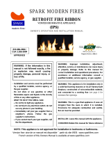
REPLACEMENT BURNER PARTS LIST
1
2
5
3
8
7
4
The log set is purchased and packaged separately. Styles and sizes will
vary depending upon the log set ordered. When ordering replacement
parts; be sure to indicate your log set and burner model.
6
16/19" model 18/20" model 24" model 30" model 36" model
Item Description Part No. Qty. Part No. Qty. Part No. Qty. Part No. Qty. Part No. Qty.
1. Grate SD-2-18 1 SX-2-18 1 SX-2-24 1 Sx-2-30 1 sx-2-36 1
2. Log locators with screws and nuts UP-8 2 UP-8 2 UP-8 2 UP-8 2 UP-8 2
3.
or
Standard burner pan
Stainless steel burner pan
GG45-2-16/19(P)
GG45-2-16/19SS(P)
1
1
GG45-2-18/20(P)
GG45-2-18/20SS(P)
1
1
GG45-2-24(P)
GG45-2-24SS(P)
1
1
GG45-2-30(P)
GG45-2-30SS(P)
1
1
GG45-2-30(P)
GG45-2-30SS(P)
1
1
4. Control valve (see inset) -- -- -- -- -- -- -- -- -- --
5. Flex connector w/ adapter CK-5-SP 1 CK-5-SP 1 CK-5-SP 1 CK-5-SP 1 CK-5-SP 1
6.
Damper clamp DC-1 1 DC-1 1 DC-1 1 DC-1 1 DC-1 1
7.
or
Sand granules (natural gas)
Vermiculite granules (propane gas)
CS-10
LF-15
1
1
CS-15
LF-15
1
1
CS-10
LF-15
2
2
CS-15
LF-15
2
2
CS-15
LF-15
2
2
8. Glowing embers EM-1 2 EM-1 2 EM-1 2 EM-1 2 EM-1 2
Replacement parts can be ordered
from your local Real-Fyre
® dealer.
Note: Photos not to scale.
(see inset)

7
L-A2-222
REV 7 - 1305221425
SAFETY CONTROL SYSTEM FOR MANUAL SERIES
SAFETY CONTROL SYSTEM FOR 17 SERIES
Pressure
tap
4
1
2
3
4
3
2
Remote
connects
here
5
6
1
DO NOT REMOVE
HEAT SHIELD
DO NOT REMOVE
HEAT SHIELD
Item Description Part No. Qty.
1. Control knob w/ extension EH-11H 1
2. Manual SPK valve SV-19 1
3. Pressure regulator, natural gas PR-3NAT 1
or Pressure regulator, propane gas PR-2LP 1
4.
or
Pilot assembly, natural gas
Pilot assembly, propane gas
PT-1NAT
PT-1LP
1
1
5. Heatshield, valve HS-32 1
6. Heatshield, regulator HS-39 1
6
5
Item Description Part No. Qty.
1. Control knob KNOB-9 1
2. Valve SV-37 1
3. Pressure regulator, natural gas PR-3NAT 1
or Pressure regulator, propane gas PR-2LP 1
4.
or
Pilot assembly, natural gas
Pilot assembly, propane gas
PT-1NAT
PT-1LP
1
1
5. remote kit (if equipped) VR-1A 1
6. Heatshield, valve HS-35 1
7. Heatshield, regulator HS-39 1
7

8
L-A2-222
REV 7 - 1305221425
SAFETY CONTROL SYSTEM FOR 11 SERIES
4
1
2
3
DO NOT REMOVE
HEAT SHIELD
Item Description Part No. Qty.
1. Heatshield HS-36 1
2 Valve assembly (natural) SV-6 1
or Valve assembly (propane) SV-6P 1
3 Pilot assembly (natural) PAC-3NAT 1
or Pilot assembly (propane) PAC-3LP 1
4.
Remote kit (if equipped)
RR-1A 1

9
L-A2-222
REV 7 - 1305221425
SAFETY CONTROL SYSTEM FOR 01 SERIES
SAFETY CONTROL SYSTEM FOR 15 SERIES
1
4
2
3
5
2
7
5
3
1
4
DO NOT REMOVE
HEAT SHIELD
DO NOT REMOVE
HEAT SHIELD
Item Description Part No. Qty.
1. Pilot assembly (natural) PAC-6 1
or Pilot assembly (propane) PAC-7 1
2. Valve assembly (natural) SV-32 1
or Valve assembly (propane) SV-33 1
3. Heat shield HS-37 1
4. Switch box assembly IMP-1 1
5 Remote kit (if equipped) RR-1A 1
Item Description Part No. Qty.
1. Pressure regulator, natural gas PR-3NAT 1
or Pressure regulator, propane gas PR-2LP 1
2. Pilot assembly (natural gas) PT-1NAT 1
or Pilot assembly (propane gas) PT-1LP 1
3.
Valve, natural gas
SV-22 1
or
Valve, propane gas
SV-23 1
4. Remote kit (if equipped) VR-1A 1
5. Heat shield, valve HS-31 1
6. Heat shield, regulator HS-41 1
7. Decorative wood chunk WC-1-5 1
6

11
IMPORTANT PRE-INSTALLATION AND FIREPLACE SAFETY INFORMATION
A. This appliance is designed as an attended appliance. Adults must be present when this gas appliance is operating.
Do not leave this unit burning when unattended or while anyone is sleeping.
B. This appliance is only for use with the type of gas indicated on the rating plate. This appliance is NOT FIELD
CONVERTIBLE for use with other gasses.
C. BE CAREFUL: If not installed, serviced, and used correctly per these instructions, this product can cause
serious personal injury, property damage, or loss of life.
D. WARNING: Before installing in a solid-fuel-burning fi replace, the chimney fl ue, damper, and fi rebox must be
thoroughly CLEANED of soot, creosote, ashes, and loose paint, and must be inspected by a qualifi ed chimney
cleaner. Some older fi replaces may need repair prior to installing this appliance.
E. CHECK GAS TYPE (natural or propane): The gas supply must be the same as stated on your burner system rating
plate. If gas supply is different, DO NOT INSTALL. Contact your dealer for immediate assistance.
F. Keep the area of the gas burner system clear and free from combustible materials, gasoline, and other fl ammable
vapors and liquids.
G. INSUFFICIENT GAS PRESSURE WILL KEEP THE PILOT (IF EQUIPPED) FROM OPERATING PROPERLY. DO NOT
USE IF GAS PRESSURE IS LOWER THAN THE MINIMUM REQUIREMENT.
H. The minimum inlet gas-supply pressure for purposes of input adjustment is 5" water column (w.c.) on natural gas
and 11" w.c. on propane gas. Insuffi cient gas pressure will affect proper operation of the pilot (if equipped). Do not
install this gas appliance if minimum pressure is not available. The maximum inlet gas-supply pressure is 10.5" w.c.
on natural gas and 13" w.c. on propane gas. The propane source must be regulated. (Do not connect this appliance
directly to an unregulated propane gas tank - this can cause an explosion.)
I. The gas piping system must be sized to provide minimum inlet pressure at the maximum fl ow rate (BTU/hr).
Undue pressure loss will occur if the pipe is too small, or the run is too long. Gas supply pipe must be
1
/
2
" minimum
interior diameter. If the gas line is longer than 20', a larger diameter line may be necessary. Refer to the NFPA 54
guidelines for further details.
J. Input ratings shown in BTU per hour are for elevations up to 2,000 ft. For elevations above 2,000 ft., refer to the National
Fuel Gas Code or contact manufacturer before installing this product.
K. This gas appliance and its main gas valve must be disconnected from the gas-supply piping system during any pressure
testing of that system at test pressures in excess of
1
/
2
psig.
L. This gas appliance must be isolated from the gas-supply piping system by closing the equipment shutoff valve connected
to the gas-supply line during any pressure testing of the gas-supply piping system at test pressures equal to or less
than
1
/
2
psig.
M. Do not use this appliance if any part has been underwater. Immediately call a qualifi ed service technician to inspect the
appliance and to replace any part of the control system and any gas control that has been underwater.
N. A fi replace screen must be in place when the system is burning. Provisions for adequate combustion air must be
maintained. Unless other provisions for combustion air are provided, the screen shall have an opening(s) for introduction
of combustion air. Combustion air is adequate when all fl ames curl into the fi replace and away from the screen. When
a glass fi replace enclosure (door) is used, leave the doors fully open when the system is in operation.
O. This appliance may be installed in an aftermarket, permanently located, manufactured (mobile) home, where not
prohibited by local codes. Installation of appliances designed for manufactured home (U.S. only) or mobile home
installation must conform with the Standard CAN/CSA Z240 MH, Mobile Housing, in Canada, or with the Manufactured
Home Construction and Safety Standard, Title 24 CFR, Part 3280, in the United States, or when such a standard is not
applicable, ANSI/NCSBCS A225.1/NFPA 501A, Manufactured Home Installations Standard.
CAUTION: Installation and repair must be done by an NFI Certifi ed or other qualifi ed professional
installer.
Installer: Carefully read these instructions before installing this gas burner system. Be sure you understand
all safety precautions and warnings contained in this manual.

12
INSTALLATION
The damper clamp with hex bolt (Fig. 12-1) is provided as a means to
prevent full closure of the damper blade. The clamp is easily attached to most
damper blades with pliers or a wrench, and must be permanently installed.
The clamp is designed to prevent accidental closure of the damper when
installed as illustrated (Fig. 12-2 and Fig. 12-3). Should the clamp not fi t, or
fail to provide the permanent vent opening listed in the table found above,
have a permanent stop installed, remove the damper
blade, or have the damper cut to provide the minimum
permanent opening required.
Note: These are minimum damper opening
specifi cations. The damper must be completely
opened when operating this gas appliance to
achieve the best ventilation possible.
Fig. 12-1
Damper clamp
Set screw
Fig. 12-2 Fig. 12-3
Open
Closed
Fig. 12-4
Gas supply
line stub
Gas line
cap
Fig. 12-5 Log locators on grate
INSTALLING THE BURNER
The Real-Fyre gas log set must be installed by a qualifi ed professional service technician. Instructions must
be followed carefully to ensure proper performance and full benefi t from the gas log set. Check to be sure the
log set is designed and labeled for the type of gas (natural or propane gas) supplied to the fi replace.
Fireplace fl oor must be level, clean, and smooth.
WARNING: Failure to position the parts in accordance with these diagrams or failure to use only parts
specifi cally approved with this appliance may result in property damage or personal injury.
REFER TO THE PARTS LIST WHEN FOLLOWING THESE INSTRUCTIONS.
1. MAKE SURE THE FIREPLACE GAS SUPPLY IS TURNED OFF.
2. Locate the gas-supply stub inside the fi replace and remove the cap, if attached (see Fig. 12-4).
CAUTION: When removing the cap, make sure the stub does not turn, loosening the connection inside the wall.
3. Locate the grate and attach the log locators to the 2 outer bars of the grate with screws and nuts. The log
locators should be positioned on the middle of the bars with screw slots facing towards fi replace side walls
(Fig. 12-5).
4. Attach the nut end of the fl ex connector to the adapter found on the valve or, if attached, on the regulator
behind the valve. Tighten securely.
5. Place the burner pan into the fi replace so that it is centered.
6. Be sure gas to the fi replace is off. Attach the large adapter end of the fl ex connector to the gas-supply stub
using a pipe compound resistant to all gases. Ensure adapter (and nut) are tightened securely. Ensure the
pan rests level on the fi replace fl oor after connection. Adjust the pan if necessary.

13
INSTALLATION (cont.)
7. LEAK TEST: Turn on the fi replace gas supply, and test at all connections for leaks using the appropriate soapy
water solution. If bubbles appear, a leak is present. Turn off the gas and tighten at all connections. Repeat
until no leaks are present. If a leak persists, turn off the gas supply and contact the local gas company or
dealer. NEVER USE A FLAME TO CHECK FOR LEAKS.
Turn off the gas supply prior to proceeding.
8. Place the heatshield over the regulator and/or valve.
Important: Heatshields must be in place during operation of the gas log set. Overheating of the valve
will cause shut down of the gas log set or other operating problems.
9. If this unit was shipped with a remote, read and follow the separate remote instructions (packed with remote)
for complete remote installation.
GRANULE, EMBER, AND GRATE PLACEMENT
GRANULE PLACEMENT
The granules supplied with the unit are specially selected for use with
either propane gas or natural gas. They maximize fl ame distribution
and reduce carbon buildup.
1. Fill the burner pan completely with the granules*. See Fig. 13-1.
Avoid spilling the granules on the pilot kit.
*Note: Use only select sand for natural gas burners and vermiculite
for propane gas burners.
2. Slope the granules at the same angle as the burner pan. This is
important to ensure quiet lighting and even fl ame distribution.
EMBER PLACEMENT
Sprinkle the glowing embers lightly and evenly over the entire surface of the granules. Break up any clumps that
may have developed during shipment.
Important: Do not add any additional embers to this log set. Any additional embers may cause unsafe
operation.
GRATE PLACEMENT
Center the grate over the burner pan.
Fig. 13-1 Granule placement
Burner pan
Granules

14
01 VALVE MODELS ONLY
CONNECTING THE IGNITION PACK TO THE VALVE
The 01valve comes complete with the wiring harness connected to the switch box. You may wish to ensure it is correctly
connected before fi nally connecting the three wires to the valve, as below.
TO CHECK THE WIRING ASSEMBLY:
A. Check that the wiring harness is fi tted tightly into the connector on the
green ignitor pack inside the switch box (Fig. 14-1).
B.
Check that the female connectors on the two black wires from the pilot
assembly (wires marked "I" and "S") are inserted fully into the male
connectors on the ignitor pack (Fig. 14-2).
C.
Check the connection of the red and black wires of the wire harness to
the respective counterpart wires from the battery holder (red-red and
black-black). The two brown wires should be connected to the switch.
Note: The two spare brown wires with coated male connectors are used
to connect a remote system (if equipped).
D. Connect the wires to the valve in the following order (see Fig. 14-2):
Orang
e wire marked THTP - to THTP connector on valve
Black wire marked TP - to TP connector on valve
Green wire marked TH - to TH connector on valve
The diagram below shows the wiring layout for the complete unit.
INSTALLING OR REPLACING BATTERIES FOR IGNITION
MODULE PACK
Two 1.5-volt (D-cell) alkaline batteries are supplied with the burner system.
To install or replace batteries, remove any old batteries (if applicable) and
install new batteries according to the diagram illustrated on the battery holder
mounted inside the switch box (Fig. 14-3).
Note:
For the system to work properly, it is suggested that you replace
the batteries annually with fresh batteries. Always replace all the
batteries at the same time.
2x D cells
(Black) to
Battery
holder
(Red) to
battery holder
Rear of control panel
w
ires
(inside
box)
Remote
receiver
(optional)
Wire harness
Remote valve
Valve magnet wire
(black)
(do not remove)
Orange (THTP)
Black (TP)
Green (TH)
I
Ignitor pack
S
Ignitor
Sensor
S
I
To pilot assembly
probes
Brown 2
wires to
switch
(inside of
switch box)
Fig. 14-5
Consult this wiring diagram to ensure correct connection of wires.
Switch
Switch box
Wiring diagram for 01 Valve
"S" wire
Fig. 14-2
Orange wire marked THTP
Black wire marked TP
Green wire
marked THTP
"I" wire
B
Check Connections
Wire harness
connector
Ignitor pack
Fig. 14-1
Battery
pack
Ignitor
pack
Switch
box
ON/OFF switch
A
D
Fig. 14-3
SWITCH BOX PLACEMENT
Place the switch box outside of the fi rebox and a minimum of 6" from the burner/fl ame. If the switch box is in the fi rebox, the
switch box must only be oriented as shown in Fig. 14-4. The switch box must not be placed in the rear of the fi replace, or in
any other manner than shown in Fig. 14-4. Set the box on its side and place the bottom of the box toward the right fi rebox wall
(box must be a minimum of 6" from the burner/fl ame). Be sure that the pilot and valve wire bundles remain clear of the burner,
valve, and heat shield at all times.
Note: Coil excess wire within the switch box.
CAUTION: THE SWITCH BOX MAY BE HOT DURING AND AFTER OPERATION.
Wire bundles go around the valve
and away from the burner. Coil
excess wire under switch box.
Fig. 14-4
Valve
wire
bundle
Pilot wire
bundle
Switch box
Valve and heat shield
Burner pan
6"
min
(FIREBOX)
IF SWITCH BOX IS INSIDE FIREBOX; ORIENT ONLY AS SHOWN
BELOW:
(FIREBOX)
BOX ON ITS SIDE
Bottom

15
LOG PLACEMENT
Fig. 15-1
CAUTION: Burn hazard. Logs will remain hot for some time after use. You must maintain the
log layout as shown to ensure proper operation of your log set. If you need to
reposition any log to maintain the proper layout, use heat-resistant gloves or allow
logs adequate time to cool before handling.
The log set is purchased and packaged separately. Styles and
sizes will vary depending upon the log set ordered. If the log set
ordered includes placement instructions; follow those instructions.
When ordering replacement parts; be sure to indicate your log
set and burner model.
Log placement is very important for the proper operation
and performance of the Real-Fyre
®
gas log set. Although you
have some fl exibility in the log arrangement, it is necessary to
follow the log placement instructions carefully to fully enjoy the
log set.
1. Place the bottom logs on the grate. The log locators ensure
that adequate space between the logs is maintained for a
clean burn (Fig. 15-1).
2. Place the middle/top logs diagonally with space betw
een the
logs so that the fl ames are not choked off. Adjust the middle/
top logs until desired look, and fl ame pattern are achieved.
Flexibility is possible provided excessive sooting does not
result from fl ames striking the logs too directly. Reference
Fig. 15-2 for some examples.
Fig. 15-2

The Real-Fyre
®
burner system has a pilot that can be lit by hand using a match or lighter. When lighting the pilot, follow these
instructions exactly.
BEFORE LIGHTING, smell all around the burner area for gas. Be sure to smell next to the fl oor, as some gas is heavier than
air and will settle on the fl oor. IF YOU SMELL GAS, FOLLOW THE INSTRUCTIONS ON P. 1.
Use only your hand to push in or turn the gas control knob. Never use tools. If the knob will not push in or turn by hand, don't try
to repair it. Call a qualifi ed professional service technician. Excessive force or attempted repair may result in fi re or explosion.
WARNING
If you do not follow these instructions exactly, a fi re or explosion may result, causing property
damage, personal injury, or loss of life.
Do not use this appliance if any part has been underwater. Immediately call for a qualifi ed professional service technician to
inspect the appliance and to replace any part of the control system and any gas control that has been underwater.
FOR YOUR SAFETY, READ BEFORE LIGHTING
LIGHTING THE PILOT
1. Push in the gas control knob slightly and turn
clockwise
to OFF (Fig. 17-1). Refer to
the PARTS LIST for the location of the burner
control valve knob.
Note: The burner control knob cannot be turned
from PILOT to OFF unless the knob is
pushed in slightly. Do not force.
Wait fi ve minutes to clear out any gas. If you then
smell gas, STOP! Notify your gas supplier or the
fi re department immediately. If you don’t smell gas,
go on to step 2.
2. Turn the burner control knob counter-clockwise
to PILOT (Fig. 17-1). Push the control
knob fi rmly and fully in and hold. Hold a long
fi replace match or lighter near the thermocouple
to light the pilot. Continue to hold the control
knob in for approximately 30 seconds after the
pilot is lit, then release the knob. The pilot will
remain lit.
• If the pilot will not light, repeat steps 1 and 2.
• If the pilot will not stay lit after several tries,
turn the gas control knob to OFF and call your
service technician or gas supplier.
IGNITING THE MAIN BURNER
1. Make sure the pilot is burning.
2. Turn the gas control knob counterclockwise
to ON (Fig. 17-1) to ignite the burner. The burner
will ignite
.
Note: Periodically check the pilot fl ame for the
proper fl ame pattern (Fig. 17-1).
MAKE SURE
THE THERMOCOUPLE AND PILOT
ASSEMBLY ARE IN CORRECT ALIGNMENT WITH
EACH OTHER (Fig. 17-1).
TURNING OFF
THE MAIN BURNER
1. From the ON position, turn the control knob
clockwise
to the PILOT position. The burner
will extinguish, and the pilot will remain lit.
EXTINGUISHING THE PILOT
1. If complete shutdown is desired, from the PILOT
position, push in the control knob slightly and
turn clockwise
to the OFF position. Do not
force the knob. This will require the pilot to be
relit before using the burner again.
17
Thermocouple
Pilot
1. Turn the knob
clockwise to OFF
only when
complete shutdown
is desired or prior to
lighting the pilot.
Fig. 17-1
1. Lighting -Turn the burner control knob
to OFF
and wait 5 minutes before
lighting.
2. Turn knob
counterclockwise
to PILOT position. With
match ready, press
knob in and hold for 60
seconds while lighting
pilot.
3. Turn the knob
counterclockwise
to ON to light the
burner.
PILO T
ON
OFF
OFF
ON
PILOT
OFF
ON
PILOT
OFF
ON
PILOT
Pilot Assembly
LIGHTING INSTRUCTIONS - MANUAL PILOT AND SERIES 17 VALVE
The series 17 valve is capable of remote operation. If this
unit was shipped with a remote, or if a remote system
was installed later, read and follow the separate remote
instructions to operate the burner remotely.
(Manual valve shown)

WARNING
If you do not follow these instructions exactly, a fi re or explosion may result, causing property
damage, personal injury, or loss of life.
LIGHTING INSTRUCTIONS - SERIES 15 VALVE
Do not use this appliance if any part has been underwater. Immediately call for a qualifi ed professional service technician
to inspect the appliance and to replace any part of the control system and any gas control that has been underwater.
Gas valve operating positions
OFF IGNITION PILOT ON
Fig. 19-1
Flame-height control knob
Fig. 19-4
Fig. 19-3
LIGHTING THE PILOT
1. Turn the ignitor control knob (Fig. 19-1) on the burner
control valve assembly to the side of the burner pan
counterclockwise so that the narrowing part of the
knob moves from the OFF position, slightly toward IGN,
until reaching the stop.
2. Press the ignitor control knob in and hold in for fi ve (5)
seconds (only pilot gas will fl ow).
3. Continue pressing in while turning the ignitor control knob
further counterclockwise toward the PILOT position
until you hear a click. The click is an indication that the
piezo ignitor has been activated.
Note: If the spark from the piezo ignitor does not
light the pilot, repeat steps 2 & 3 until the pilot
lights.
4. Continue to hold the ignitor control knob in the PILOT
position for 60 seconds after the pilot has been lit to allow
the thermocouple to detect the pilot fl ame.
Note: The pilot fl ame should always be present when
the burner system is in operation, and should just
envelop the tip of the thermocouple.
IGNITING THE MAIN BURNER
1. When the pilot fl ame is stable, release the ignitor control
knob and turn counterclockwise to the ON position
to enable the main burner.
2. Turn the flame-height control knob (Fig. 19-3)
countercloc
kwise
to the fully ON position
(Fig. 19-4) to ignite the burner at maximum BTUs.
After the main burner ignites, adjust the fl ame height
as indicated below.
ADJUSTING THE FLAME HEIGHT
1. To adjust the fl ame, turn the fl ame-height control knob
(Fig. 19-3) counterclockwise to increase the fl ame
height, or clockwise to decrease the fl ame height,
until the fl ames have the desired characteristics.
2. When you are fi nished enjoying your fi re, turn the fl ame-
height control knob to OFF. The pilot will remain lit. The
burner system can be relit by rotating the fl ame-height
control knob toward ON.
SHUTTING OFF THE PILOT
If you do not plan on using your burner system for an
extended period, you may elect to extinguish the pilot. To do
this, rotate the fl ame-height control knob to the OFF position
and then rotate the ignitor control knob to the OFF position
(Fig. 19-1).
Important: When shutting the burner system down
completely, turn the control/ignition knob to
the OFF position (Fig. 19-1). If you desire to
turn the unit back on, wait a minimum of one
(1) minute before starting the relight procedure
(LIGHTING THE PILOT). This allows the safety
valve to reset in preparation for relighting.
If this unit was shipped with a remote, or if a remote
system was installed later, read and follow the separate
remote instructions to operate the burner remotely.
FOR YOUR SAFETY, READ BEFORE LIGHTING
Control/
ignition
knob
Flame-height
control knob
OFF ON
19
Fig. 19-2
Thermocouple
The Real-Fyre
®
burner system has a pilot. When starting the pilot, follow these instructions exactly.
BEFORE LIGHTING, smell all around the gas burner system area for gas. Be sure to smell next to the fl oor, as some gas
is heavier than air and will settle on the fl oor. IF YOU SMELL GAS, FOLLOW THE INSTRUCTIONS ON P. 1.
Use only your hand to push in or turn the gas control knob. Never use tools. If the knob will not push in or turn by hand, don't
try to repair it. Call a qualifi ed professional service technician. Force or attempted repair may result in fi re or explosion.
Fig. 19-2
Thermocouple

IN
TH
TP
TH
TP
IN
OUT
ADJUSTING THE PILOT
a. The pilot fl ame should encircle the generator tip,
and is preset at the factory (Fig. 21-2).
b. If adjustment is necessary (Fig.21-1), turn the gas
adjustment screw counterclockwise
to increase
the pilot fl ame, or clockwise
to decrease the
pilot fl ame.
MAINTENANCE
Your pan burner is equipped with a safety pilot that will
shut off the gas supply in the event that the pilot is not
functioning properly. Make sure the pilot is adjusted
properly and that the generator spade clips are tightly
connected to the terminal screws on the valve. If the
pilot will not stay lit, call your local gas utility or gas
supplier.
A periodic check of the following should be performed
at least annually by a qualifi ed professional service
representative:
1. Valves and toggle switch control for proper
operation.
2.
Flue system for rust, damage, or leaks.
3. Damper operation.
4. Orifi ces for dirt or other foreign matter.
5. Visual check on the burner.
If this unit was shipped with a remote, or if a remote
system was installed later
, read and follow the
separate remote instructions to operate the burner
remotely.
WARNING
If you do not follow these instructions exactly, a fi re or explosion may result, causing property
damage, personal injury, or loss of life.
Do not use this appliance if any part has been underwater. Immediately call for a qualifi ed professional service technician
to inspect the appliance and to replace any part of the control system and any gas control that has been underwater.
FOR YOUR SAFETY, READ BEFORE LIGHTING
LIGHTING THE PILOT
To read the safety valve control knob (Fig. 21-1),
read the marking nearest the teardrop-shaped metal
pointer
.
1. If the safety valve control knob is in the PILOT
position, push in slightly on the knob and rotate it
clockwise
to the OFF position.
2. Release knob and wait fi ve (5) minutes.
3. Turn safety valve knob counterclockwise to the
PILOT position. (Only the pilot gas will fl ow when
the knob is pushed in.)
4. Place a long match or a butane lighter at the pilot
burner, and at the same time, push the safety valve
knob fully in. The pilot will light.
5. Hold the safety valve knob in for approximately 60
seconds before releasing.
6. If the pilot does not stay lit, turn the safety valve
knob clockwise
to the full OFF position. Wait fi ve
(5) minutes, then repeat steps 3 through 5.
IGNITING THE MAIN BURNER
With the pilot lit, turn the safety valve knob counterclockwise
to the ON position. Switch the toggle switch control
to the ON position, and the burner will light. Refer to the
P
ARTS LIST for the toggle switch location.
SHUTTING OFF THE MAIN BURNER
Switch the toggle switch control to the OFF position. The
pilot will remain lit.
SHUTTING OFF THE PILOT
Be sure the toggle switch control is OFF and depress
and turn the safety valve knob clockwise
to the OFF
position.
Fig. 21-1
Wiring harness
Toggle switch
Pilot screw
Pilot gas
port
control
knob
Safety
valve
To remote
(if applicable)
21
LIGHTING INSTRUCTIONS - SERIES 11 VALVE
The Real-Fyre
®
burner system has a pilot that can be lit by hand using a match or lighter. When lighting the pilot, follow
these instructions exactly.
BEFORE LIGHTING, smell all around the burner area for gas. Be sure to smell next to the fl oor, as some gas is heavier than
air and will settle on the fl oor. IF YOU SMELL GAS, FOLLOW THE INSTRUCTIONS ON P. 1.
Use only your hand to push in or turn the gas control knob. Never use tools. If the knob will not push in or turn by hand, don't
try to repair it. Call a qualifi ed professional service technician. Force or attempted repair may result in fi re or explosion.
Generator
Pilot
Note: Pilot fl ame should encircle top of the generator.
Fig. 21-2 Lighting the pilot

23
1. STOP! Read the safety information above.
2. Turn off any electrical appliance used with the
burner system.
3. Verify the switch (marked I = IGNITE; O = OFF)
located on the front of the switch box is set to
"O" (OFF). Do not force.
4. Wait fi ve (5) minutes to clear out any gas. If
you then smell gas, STOP! Follow the safety
information above. If you don't smell gas, go to
the next step.
5. Depress the "I" (IGNITE) switch on the front of
the switch box. This transmits a rapid series of
sparks at the pilot head. These sparks cease
when the pilot fl ame is lit and stable. The pilot is
located at the rear right corner of the burner.
After a short time, the pilot will light the main
burner.
CAUTION: IF THE GAS SET DOES NOT
IGNITE WITHIN 20 SECONDS,
STOP, PRESS "O" (OFF), WAIT
FIVE (5) MINUTES, THEN REPEAT
STEPS 3-6.
• The pilot should remain lit. If it goes out, repeat
steps 3 through 6.
• If the pilot will not stay lit after several tries, turn the
switch box to "O" (OFF) (Fig. 23-1) and call your
service technician or gas supplier.
6. To turn the set OFF, press the "O" (OFF) switch
on the front of the switch box. The gas fl ow will
cease, and all fl ames will go out.
If this unit was shipped with a remote, or if a
remote system was installed later, read and follow
the separate remote instructions to operate the
burner remotely.
1. Put the switch in the OFF position. The burner will extinguish, and the pilot will go out.
1. LIGHTING - Verify the switch (marked I = IGNITE; O =
OFF) located on front of the switch box is set to O. Wait
fi ve (5) minutes for the gas to clear out.
LIGHTING INSTRUCTIONS - SERIES 01 VALVE
WARNING: If you do not follow these instructions exactly, a fi re or explosion may
result, causing property damage, personal injury, or loss of life.
BEFORE LIGHTING,
smell all around the gas burner area for gas. Be sure to smell next to the fl oor,
because some gas is heavier than air and will settle on the fl oor. IF YOU SMELL GAS, FOLLOW THE
INSTRUCTIONS ON P. 1.
Fig. 23-1
1. Press O (OFF) when
complete shutdown
is desired.
2. Press I (IGNITE)
After a series of rapid
sparks, the pilot will
light. When the pilot is
stable, the main burner
will ignite.
SHUT-OFF INSTRUCTIONS - SERIES 01 VALVE
FOR YOUR SAFETY, READ BEFORE LIGHTING

24
POSSIBLE CAUSE SOLUTIONS
BURNER SHUTTING DOWN DURING OPERATION
A. Insuffi cient or excessive gas
pressure
A1. Check gas pressure (Read G.- I. of IMPORTANT PRE-INSTALLATION AND
FIREPLACE SAFETY INFORMATION section, & check with local gas company).
A2. Other gas appliances may be on the same gas line, dropping gas pressure
to log set. Check pressures with everything operating to ensure adequate
pressure.
B. Log placement B. Reference the LOG PLACEMENT section in this manual for recommended
log positioning.
C. Flue area, fireplace, or
damper dirty from soot
C. Clean around, above, and under damper thoroughly. Clean fi replace, removing
loose material, including soot and creosote.
D. Fireplace too small for unit D. Ensure minimum requirements are met. (See FIREPLACE SIZE
REQUIREMENT section in this owner’s manual.)
E. Pilot flame lifting off
thermocouple/generator
E. Check gas pressure (see section A1).
F. Pilot (remote compatible) F. Contact your dealer for instructions on replacement.
G. Blockages on burner G. Vacuum any lava granules or material that may have fallen onto burner pipe area.
PILOT WILL NOT LIGHT
A. Pilot flame lifting off
thermocouple/generator
A. Check gas pressure (see Section 1, A1 of this table).
B. Electronic spark not lighting
pilot
B. Check to assure sparking when activated.
Note: You may need to turn or press ignitor several times to ignite pilot. See
LIGHTING INSTRUCTIONS for your control valve.
C. Ignitor electrode wire loose C. Check wiring and reconnect any loose wiring.
D. Gas supply off/manual
shutoff valve closed
D. Turn on gas supply or open manual shutoff valve.
E. Air in gas line E. Bleed the gas supply line and repeat LIGHTING INSTRUCTIONS until air is
removed.
F. Pilot hood blocked F. Check for debris or dirt / Clean pilot
G. Dead batteries (electronic
pilots only)
G. Replace batteries as needed.
TROUBLESHOOTING
2
1
LOW FLAME HEIGHT
A. Gas pressure A. Check gas pressure (see Section 1, A1 of this table).
B. Propane tank running low B. Fill tank completely.
BURNER NOT BURNING EVENLY
A. Burner orifi ce clogged A. Clean burner orifi ce.
B. Top burner lights; bottom
burner has delayed ignition.
B1. Check gas pressure. Can be caused by too small of a gas line (see Section
1, A1 of this table).
B2. Low propane tank level. Vacuum burner tube for soot blockage and fi ll propane
tank.
ODORS
A. Gas leak A. Shut off gas, if possible. Follow instructions on front page. Have a qualifi ed
professional installer or the gas company correct all leaks.
B. New home, new carpet, or
new paint
B. When these odors are drawn into the fi replace, this may cause objectionable
odors. Thoroughly ventilate the area before restarting your log set.
3
4
5

25
POSSIBLE CAUSE SOLUTIONS
SOOTING
A. On logs, in fi rebox, or room A. Check gas pressure (see Section 1, A1 of this table).
B. Drafts in room B. Eliminate drafts by closing heating and air conditioning
vents, returns, and outside air vents. Fans blowing directly
into fi replace should be turned off when set is operating.
C. Air shutters blocked (if applicable) C. Air shutters are blocked with debris. Vacuum debris away
from air shutter.
D. Log placement D. See solution in Section 1, B.
E. Using natural-gas burner on propane gas or
propane burner on natural gas
E. If the gas listed on the nameplate does not match the gas
you are burning, shut down the burner system immediately
and completely (including pilot) following the steps in
the LIGHTING INSTRUCTIONS section. Then call your
dealer.
F. Adding any accessories to log sets F. Shut down log set and take off any logs or accessories that
do not belong with the set.
PILOT WILL NOT STAY LIT
A. Valve won’t hold A. Contact your dealer for instructions on replacement.
B. Pilot hood not aimed at thermocouple B. Pilot hood bent; replace pilot or angle pilot hood properly so
pilot fl ame hits thermocouple.
C. Pilot line bent C. Replace pilot line.
D. Thermocouple is loose D. Tighten thermocouple nut at gas control valve.
E. Thermocouple cracked or worn out E. Replace thermocouple.
F. Excessive down draft F. Install chimney cap / Outside chimney too close to other
peaks / Check chimney fl ue for proper height / Poorly
designed chimney
6
7
TROUBLESHOOTING (Cont.)
Observe the fl ames. The main burner fl ames should
be blue at the base and a combination of blue/
yellow at the body and at the tips. They should be
5"(127mm) to 8"(203mm) above the logs, with the
center fl ame being the tallest (see cover photo).
The ember fl ames should be
1
/
4
" (6mm) above
the embers.
FLAME DESCRIPTION

26
PLEASE KEEP A COPY OF YOUR SALES SLIP FOR PROOF OF PURCHASE
This warranty applies to the original purchaser and to single family residential use only. It commences from date of purchase, and is valid only with
proof of purchase.
This warranty does not cover parts becoming defective through misuse, accidental damage, electrical damage, improper handling, lack of routine
maintenance, storage, and/or installation. Product must be installed (and gas must be connected) as specifi ed in the instructions or operator’s
manual, by a qualifi ed professional installer. Accessories, parts, valves, remotes, etc., when used must be Peterson Co. product.
This warranty does not apply to rust, corrosion, oxidation, or discoloration, unless the affected component becomes inoperable. It does not cover
labor or labor-related charges.
This warranty specifi cally excludes liability for indirect, incidental, or consequential damages. Some states do not allow the exclusion or limitation of
incidental or consequential damages, so the above exclusion may not apply to you. This warranty gives you specifi ed legal rights, and you may have
other rights that may vary from state to state.
For additional information regarding this warranty, or to place a warranty claim, contact the R.H. Peterson dealer where the product was purchased.
TO REGISTER YOUR PRODUCT ONLINE GO TO: WWW.RHPETERSON.COM,
AND CLICK ON PRODUCT REGISTRATION. THANK YOU FOR YOUR PURCHASE.
PETERSON VENTED DECORATIVE GAS APPLIANCE
LIMITED WARRANTY
All Peterson gas logs are WARRANTED for as long as you own them (lifetime).
All Peterson burner assemblies are WARRANTED for TEN (10) YEARS.
All Peterson glass is WARRANTED for FIVE (5) YEARS.
SPK-26 controls are covered by a THREE (3) YEAR “All Parts” Warranty.
APK-17 controls are covered by a TWO (2) YEAR “All Parts” Warranty.
All other Peterson valves, pilots, and controls are covered by a ONE (1) YEAR Limited Warranty (excluding batteries).
Robert H. Peterson Co. • 14724 East Proctor Avenue • City of Industry, CA 91746
WARRANTY
FOR USE IN THE COMMONWEALTH OF MASSACHUSETTS
INSTALLATION OF THIS APPLIANCE MUST BE PERFORMED BY A MASSACHUSETTS
LICENSED PLUMBER OR GAS FITTER ONLY.
CONNECTOR KITS USED FOR INSTALLATION AND OPERATION OF THIS APPLIANCE MUST
NOT BE MORE THAN 36" IN LENGTH.
FIREPLACE DAMPER MUST BE REMOVED OR PERMANENTLY
FIXED/WELDED IN FULL OPEN POSITION PRIOR TO
INSTALLING THIS PRODUCT.
Quality Check Date:_________________
Burner Orifi ces Nat. L.P. Leak Test: ___________ Model#: ___________________
Main: ____ ____ Burn Test: ___________ Serial#: ___________________
Other: ____ ____ Gas Type:
Nat. / L.P. Air Shutter: ___________________
Inspector: ___________________
/