SERVICE BULLETIN
Concerning 6000 Series English
Rark
Dart Gases
June 6, 1988
WARNING--DISCONNECT ELECTRICAL POWER BEFORE
ATTEBPTING
SERVICE
A problem has arisen concerning the location rhere the target inter-
face board ribbon cable connects into the
sain
P.C.board on the 6000
and
Super 6 Plus games.
Apparently, the trace that runs the control-
ling voltage for the target
lasps
is located directly beneath the
area where this ribbon cable Is plugged in.
There is a thin coating of
insulating film covering this trace,
but after a period of
tiae
this
coating can rear off, leaving the copper trace exposed. Due to the
construction of the Target Interface ribbon cable, vhen the coating is
no longer present, the rav edges of the ribbon say make contact vith
this copper trace,
vhich
can cause target
lamp
flicke'ring,
sinulate a
stuck segment, or simulate a throvn dart. A stuck segment simulation
locks up the
gaee
if the ribbon sakes constant contact, but
sany
tises
the ribbon
vi11
short momentarily vhen a vibration occurs to the P.C.
board, such as vhen throving a dart or touching the Select or Player
Change buttons. This type of short say result In the game shoving an
extra dart throvn In a round, or the gase nay reset during play.
What to do:
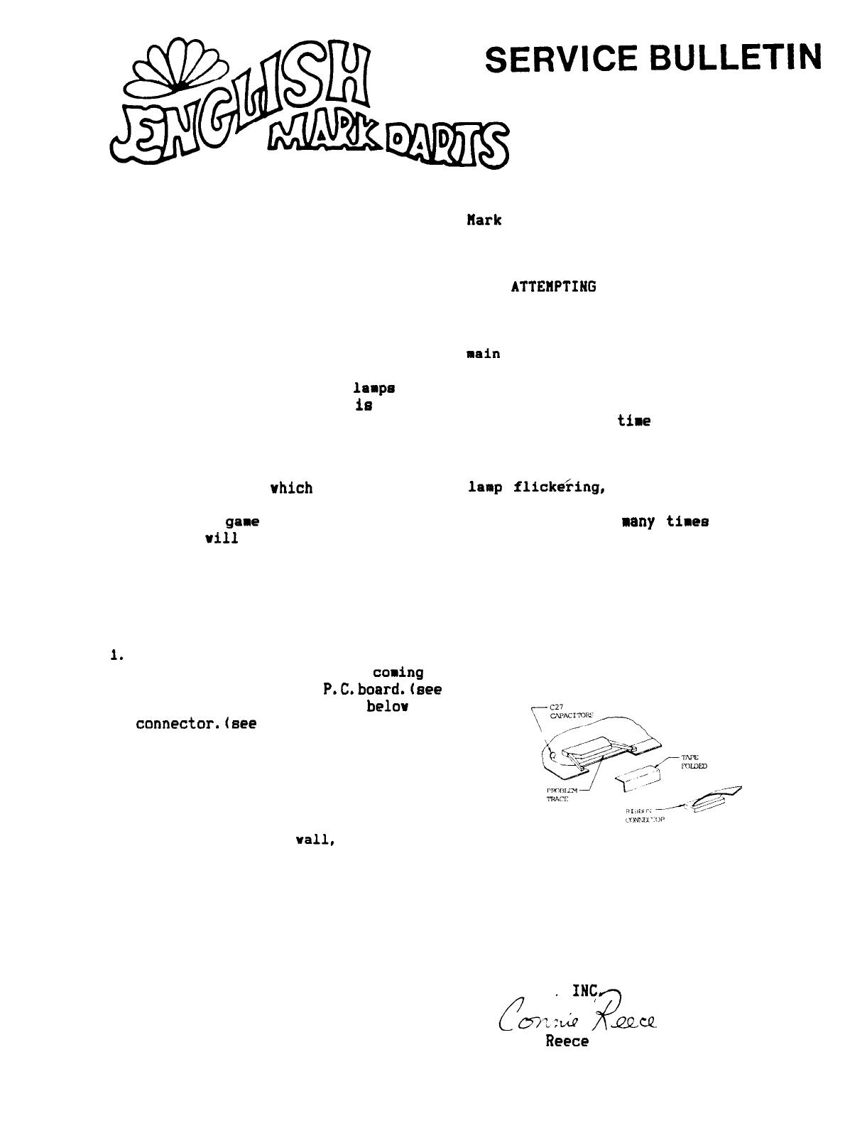
1.
Turn off gane, and unplug fros wall outlet!
2. Disconnect the ribbon cable
casing
from the
T.I.board to the main
P.C.board.(see
fig.11
3. Locate the trace that runs
belov
the ribbon
connector.(see
fig.11
4. Using a piece of electrical tape, cover the
trace completely at the connector location,
and fold tape down over the P.C. board edge
(to keep connector from catching on tape).
5. Re-insert the ribbon cable into the header
on the main P.C.board.
6. Plug game into the
vail,
and turn it on.
7. When servicing the game in the future,
periodically check the placement of the
tape, to be sure it has not shifted.
FIG.1
If there are any questions regarding this or any other service problem,
please call ARACHNID, INC. at 800-435-8319 (in Illinois; 815-654-0212).
ARACHNID.
INCfi
Connie
Reece
Design Engineering Tech.