
d–fence
Electronic invisible fence
Service instructions

2
Thank you for purchasing the product DOGtrace™ d–fence
from VNT electronics s.r.o., Czech Republic.
We would like to ask you for reading this manual carefully before using the unit
and keeping it for future use.
EC Declaration of Conformity ● Guideline R&TTE 1999/5/CE
The manufacturer: VNT electronics s.r.o. declares that the below mentioned product:
The electronic invisible fence for dogs DOGtrace™ d–fence
Complies to all Europe Council guidelines, under No. 1999/5/CE of 7. 4. 1999
And corresponds to the following standards:
EN 300 230-2, ETS 300 683 Ed. 97, EN 60335-1
CE
Preface . . . . . . . . . . . . . . . . . . . . . . . . . . . . . . . . . . . . . . . . . . . . . . . . . . . . . . . . . . . . . . . . . . . . . . . . . . . . . . 3
Scope of delivery . . . . . . . . . . . . . . . . . . . . . . . . . . . . . . . . . . . . . . . . . . . . . . . . . . . . . . . . . . . . . . . . . . . . 3
Optional accessories . . . . . . . . . . . . . . . . . . . . . . . . . . . . . . . . . . . . . . . . . . . . . . . . . . . . . . . . . . . . . . . . . 3
Principle of DOGtrace™ d–fence operation . . . . . . . . . . . . . . . . . . . . . . . . . . . . . . . . . . . . . . . . . . . 4
System installation . . . . . . . . . . . . . . . . . . . . . . . . . . . . . . . . . . . . . . . . . . . . . . . . . . . . . . . . . . . . . . . . . . 5
Turning ON/OFF . . . . . . . . . . . . . . . . . . . . . . . . . . . . . . . . . . . . . . . . . . . . . . . . . . . . . . . . . . . . . . . . . . . . . 7
Zone width setting (”warning“ and ”correcting“ zones) . . . . . . . . . . . . . . . . . . . . . . . . . . . . . . . 8
Correction pulse intensity setting . . . . . . . . . . . . . . . . . . . . . . . . . . . . . . . . . . . . . . . . . . . . . . . . . . . . 9
Three functions of the safety system . . . . . . . . . . . . . . . . . . . . . . . . . . . . . . . . . . . . . . . . . . . . . . . . 10
Replacement of electrodes . . . . . . . . . . . . . . . . . . . . . . . . . . . . . . . . . . . . . . . . . . . . . . . . . . . . . . . . . 10
Checking your DOGtrace™ d–fence . . . . . . . . . . . . . . . . . . . . . . . . . . . . . . . . . . . . . . . . . . . . . . . . . 10
Training method . . . . . . . . . . . . . . . . . . . . . . . . . . . . . . . . . . . . . . . . . . . . . . . . . . . . . . . . . . . . . . . . . . . . 11
Tips and information . . . . . . . . . . . . . . . . . . . . . . . . . . . . . . . . . . . . . . . . . . . . . . . . . . . . . . . . . . . . . . . 11
Warranty . . . . . . . . . . . . . . . . . . . . . . . . . . . . . . . . . . . . . . . . . . . . . . . . . . . . . . . . . . . . . . . . . . . . . . . . . . . 13
Characteristics . . . . . . . . . . . . . . . . . . . . . . . . . . . . . . . . . . . . . . . . . . . . . . . . . . . . . . . . . . . . . . . . . . . . . . 13
Contents
VNT electronics s.r.o. ● Němčice 23 ● 561 18 Němčice u České Třebové
Czech Republic ● Phone: +420 461 310 762 ● www.dogtrace.com

3
Preface
Do you have a wandering pet not paying attention to your protests who likes traveling
nearby and far from your house? Or is it a garden lover who likes your garden patches
or a swimmer who loves swimming in your pool? Are you afraid of the fact that your pet
may cause a road accident or it may become its victim? The electronic invisible DOGtrace™
d–fence, consisting of the transmitting generator, the antenna wire, and the collar will help
you limit the range of movement of your dog, create the “prohibited zones“, without
depriving it of its freedom of movement.
The d–fence is a modern and highly effi cient system enabling one or more dogs to run
freely in the area, fenced or fenceless, which you will provide it.
● Collar
● Electrodes
● CR2 3V lithium battery
● Neon test discharge lamp
● Transmitting generator
● Power adapter
● 100 m insulated wire 1 mm
2
(does not contain d–fence 400)
● Antenna connector
● Service instructions and Certifi cate of Warranty
● 2 connectors for connecting wires
● Transmitting generator holder
● Magnet with a neck string
● Other collars (fore more dogs)
● Dummy collars
● Varicolored woven belts
● Spare electrodes
● Spare battery
● 100 m of insulated wire 1–2,5 mm
2
● Connectors for connecting wires
● Plastic targets for marking zones
● Spare seals
● Spare screws
Scope of delivery
Optional accessories

4
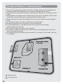
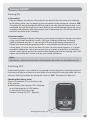
● The unit in the emergency mode is waiting for the dog coming to the prohibited zone
border (formed by an insulated wire as an antenna), divided into two zones.
● If the dog crosses the border of the fi rst (warning) zone, the collar starts emitting sound
signals.
● If the dog does not respond to the sound warning and crosses the border of the second
(correction) zone, the collar emits a signal and adds an electric pulse.
● After the dog returns from the prohibited zone, the system switches to the emergency
mode.
● It is possible to adjust the widths of both zones in defi ned limits.
● The dog will quickly learn to move only in the restricted area.
● To increase effi ciency, it is possible to mark the restricted area with targets
(refer to Optional accessories).
● The number of dogs with collars is not restricted.
● The antenna (a loop of insulated wire) is fed by the transmitting generator and it must
not be interrupted anywhere.
● The voltage within the antenna does not exceed 12 V so there is no risk even if the wire
is interrupted.
Principle of DOGtrace™ d–fence operation
1
Warning zone
2
Correction zone

5
Transmitter
● The transmitter must be located in a safe place protected against water and moisture.
It withstands temperature variations (within technical conditions), however, the penetra-
tion of water would destroy it.
● Fix the transmitter onto the internal wall near to a power socket (220 V).
● Connect the transmitter to the power adapter by plugging the adapter cable
in the transmitter and by plugging the adapter in the mains socket outlet.
System installation
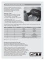
1
Loop interruption LED
2
Unit status LED
3
Correcting zone setting
4
Warning zone setting
5
Antenna wire connector
6
Adapter connector
7
Power ON/OFF
1
2
4
3
5 6
7
Transmitter description

6
Antenna wire
To make the system work, the wire must be connected to the transmitter and it must form
an uninterrupted wire loop of 1 mm
2
to 2,5 mm
2
cross section, depending on the loop
length. Unreel the wire from the transmitter round your piece of land. To take the wire out
of the garage, your house, or any other covered location where the transmitter is located,
pull it through the window, door or do it in another suitable way. The wire can be laid on
the ground, slightly buried (max. 5 cm deep), or it can be fi xed to the existing fence or wall
(in this case max. up to 30 cm above the ground). The wire must not be tight or it might
get broken due to changes in temperature.
If you need more than 100 m of the antenna wire, you must extend it with another wire of
necessary length using vampire connectors or in any other suitable and reliable way.
However, the point of connection (nor any other portion of wire) must not be left uninsu-
lated. With the vampire connectors delivered by us, it is not necessary to remove the insu-
lation from the end of the wire. If you wish your dog to pass freely across a certain location
in your piece of land where the wire must be led (e.g. between the transmitter located in
the garage and the wire installed round your piece of land), coil the outgoing wire round
the incoming one: the wires twisted round each other result in extinction of emitted waves.
Do not shape the wire at right angles, but make preferably wider curves if possible.
After you have made the loop and you are back with the other end at the transmitter,
remove insulation from both ends of the wire and fi x them to the transmitter connector
using two screws.
Insert the connector in the appropriate port of the transmitter (the connector is shaped
and it can be inserted in one way only).
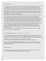
Restricting targets (refer to Optional accessories)
They enable your dog to see the zone where it can freely move as well as the boundaries
it may not get over (if the wire is laid across the place where the boundary is not restricted
in a natural way, such as a hedge). It is recommended to place the marks along the internal
edge of the acoustic warning zone, close enough to one another.
As soon as your dog is familiar with its borderline, the marks can be removed.
Before installing your DOGtrace™ d–fence system, it is useful to make a small sketch of
your piece of land and indicate the layout of your antenna wire, especially its connectors
(refer to the diagram).
Antenna wire
By winding the outgoing wire round the incoming one the wave emissions are mutually
suppressed and the animal can freely move within this location.

7
Turning ON
● Transmitter
Plug the adapter connector in the socket on the back of the transmitter unit and plug
in the power outlet. You can power up the transmitter by the setting the switch to ”ON“.
The green LED on the front panel will be lit and in the case that the antenna wire is not
connected, the red LED (Loop error) starts fl ashing on and off and the transmitter starts
sounding intermittently. After the antenna wire is connected, the LED will be steadily lit
and the transmitter stops sounding.
● Receiver (collar)
Insertion (replacement) battery: Remove 4 screws from the receiver housing cover plate
using a cross-head screwdriver. Install a CR2 type 3V battery following the proper
polarity, indicated with the ”+“ sign on the PCB next to the battery compartment.
A beep will sound indicating that the collar is active. Make sure that the seal is in its
correct place, i.e. in the slot on the housing cover. To retain water-tightness, it is recom-
mended to replace this seal at least once a year, or in order to extend its serviceability,
spread it with silicone grease from time to time. Replace the receiver housing cover and
tighten reasonably the 4 screws with the cross-head screwdriver.
Note:
After battery replacement the collar will remember the mode you selected previously.
Turning ON/OFF
Switching OFF
If the receiving collar is not used for a long period of time, the battery should be removed.
If you want to take your dog out of your piece of land, take off its receiving collar. You can
also turn off the transmitter by setting the switch to ”OFF“. The green LED goes out.
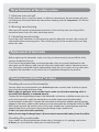
Checking the battery status
There is an indicator LED on the front side
of the receiver.
● Weak battery: the indicator LED is blinking
in red. Exchange the 3V CR2 battery
as described in the user guide
(chapter Turning ON/OFF – Receiver)
Battery polarity sign

8
With your transmitter you can extend and reduce the width of the warning and correcting
zones, depending on conditions in your piece of land and upon how the wire is laid.
a) The warning zone (sound signal)
It is infi nitely adjustable from 0,40 m to 5 m (the detection distance is approximate, depen-
ding on the loop length and location of the wire) along both sides of the wire using the
knob located on the transmitter panel. Steps 0 to 10 will help you defi ne the zone width
according to your needs, whereas it approximately holds true that 0 = 0,40 m and 10 = 5 m.
b) The correcting zone (pulses)
It is infi nitely adjustable from 0,30 m to 1,50 m (the detection distance is approximate,
depending on the loop length and location of the wire) along both sides of the wire. Steps
0 to 10 will help you defi ne the one width according to your needs, whereas it approxi-
mately holds true that 0 = 0,30 m and 10 = 1,5 m.
c) Checking and setting the zones
Before you let your dog enter its restricted area, you should physically check the surface
and boundaries of your piece of land assigned to your pet. For this purpose, fi rst place the
leads of the testing discharge lamp under the electrodes of the receiving collar; release
them slightly and then fasten them slightly again so that they can press down the testing
lamp wires. Install a battery in the receiving collar and then power up the transmitter by
setting the switch to the left to “ON“. Set both potentiometer knobs to ”0“ position.
Correcting zone setting
Select a distance from the antenna wire where you wish to defi ne the correcting zone for
your dog, stand up on that place and hold the receiving collar by the strap about 30 cm
above ground with the logo facing to the antenna wire.
Then, turn slowly the potentiometer to adjust the correcting zone as long as the test LED is
regularly on in given intervals (approximately after 1 second) along with audible sound signal.
Warning zone setting
The procedure is the same as the previous one. Select a distance from the antenna wire
where you wish to defi ne the warning zone for your dog, stand up on that place and hold
the receiving collar by the strap about 30 cm above ground with the logo facing to the
antenna wire. Then, turn slowly the potentiometer to adjust the warning zone as long as
a rapid intermittent sound signal is heard.
Important:
The zone width is changed according to the length and location of the antenna wire
in your piece of land. The longer the antenna wire is, the narrower are the zones.
The longer the antenna wire is, the narrower the zones are. The width may also be
diff erent at the bends (in the corners) compared to straight sections.
Zone width setting (”warning“ and ”correcting“ zones)

9
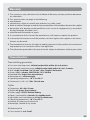
Correction pulse intensity setting
There are 8 modes for setting a correction
pulse level and 1 mode for testing intensity
of interference signals. You can adjust
correction level according to size and
sensitivity of your dog.
Changing a mode
● Turn the receiver on (battery inserted).
● Place the magnet, to a target marked
on the receiver – see picture X.
● A certain number of beeps are emitted
indicating a mode (1–9).
● After the required mode is set, remove
the magnet from the receiver. The receiver
saves the mode confi guration into its memory.
The table below shows how d–fence works in diff erent modes and recommends the right
mode according to dog breeds sizes.
Interference Signal Intensity Test (ISIT)
The unique and patented ISIT function enables the
detection of interference signal intensity where the wire is
being laid. This helps avoid potential functionality problems
of the d–fence system. In the ISIT mode (mode no. 9),
the receiver detects intensity of interference signals.
A red LED diode starts blinking when an interference signal
is detected. The blinking frequency increases with increasing
intensity of interference signals. If the LED diode shines
permanently, the interference signal intensity is very high.
It is not recommended to lay a wire in an area where
an interference signal is detected. It could signifi cantly
infl uence correct functionality of the d–fence.
Note: The device is set to mode 4 by default.
No. of beeps
1
2
3
4
5
6
7
8
9
Dog breed size
small
small
small
medium
medium
large
large
large
Level of correction
very low
low
medium
higher
high
very high
extremely high
maximum
Mode
1
2
3
4
5
6
7
8
9
Interference signal intensity test (ISIT)

10
Before replacing the electrodes, make sure that you have correctly turned off the collar
(remove the battery from it).
If you have a longwooled dog, use long electrodes (they are typically delivered as the
accessories to the delivery) and vice versa (for short electrodes, refer to Optional accesso-
ries). Electrodes should be slightly tightened by hand. Do not use pliers or any other tools
to tighten the electrodes as you can cause an irreparable damage to the product.
Replacement of electrodes
Checking the correct functionality
You can check any time whether your d–fence operates correctly and visualize its opera-
tion using the testing discharge lamp.
Before you are going to carry out this check, make sure that the receiving collar is
turned off (the battery is removed from it).
Connect the testing discharge lamp to the electrodes and ensure a reliable contact (you can
pull in the lamp wires under the electrodes or to make a loop round the electrodes).
Install a battery in the collar. Connect the transmitter to the power adapter (plug the power
adapter in the mains socket outlet) and turn on the transmitter by setting the switch to ”ON“.
Walk slowly towards the antenna wire. At fi rst you should hear a warning beep and after
approaching closer to the wire, the testing discharge lamp should be lit.
In this case your unit works perfectly.
Before the testing discharge lamp is disconnected, remove the battery from the collar!
Checking the preset mode
If you need it or when the behavior of your dog is changing as it is getting used to the
d–fence, you can check the mode you set some time ago.
Checking your DOGtrace™ d–fence
1. Antenna wire cut-off
If the antenna wire is cut off (or there is a failure in connection), the transmitter will warn
you about the functional failure by intermittent beeping and the “Loop error” LED fl ashes
on and off .
2. Warning zone leaving
After some 20 seconds of permanent presence in the warning zone, your dog will be
warned to leave it by a few short correcting pulses.
3. Correcting zone leaving
If your dog stays motionless in the correcting zone for about 20 seconds, the system will
stop emitting the correcting pulses. The correcting cycle will be restored, after your dog
leaves this zone.
Three functions of the safety system

11
We are starting to use the collar
The initial period of use can start when the young dog is at the age of 6 months after its
elementary training is fi nished. Do not put the receiving collar on a pet being in poor state
of health (heart problems, epilepsy, etc.) or to a dog that has problems with its behavior.
The dog will need to get used to wearing the collar: let him wear it for a few days without
applying to it.
Proceed gradually and slowly
It is necessary to draw attention of your dog so that it can create quickly a link between its
incorrect behavior and its correction, fi rstly by the sound signal: “sound warning zone“ fol-
lowed by the ”correcting zone“ pulse. The marks can help it visualize the beginning of the
warning zone.
Encourage it by patting and stroking
After being admonished by a pulse, when the pet has already learned to obey and return,
it should be encouraged. The pet will understand it much more quickly and its eff orts to
obey will be growing. When it is fully aware of the link between the pulse and its wrong
behavior, you can devote to your own work, but never forget to encourage it for its good
behavior in order to strengthen its ability to understand the ”conception of obedience“.
Training method
For the best results
Adjustment and positioning of the collar
It is very important to adjust the collar around dog’s neck properly. Its positioning permits
to detect the dog’s breakaway from the permitted area and makes the electric correcting
pulses to be effi cient. If you want to obtain the best results from your unit, you must
ensure a good contact between the collar and the dog’s skin by careful adjustment of
the belt; when the belt is too loose, it will not work properly; when it will be too tight, the
dog may have problems with breathing or it will be uncomfortable for it.
If it is necessary, replace the long electrodes with short ones (refer to the section about the
replacement of electrodes).
Battery check
Make sure that the battery is in order; its state may infl uence the correct operation of the
receiving collar. When the temperatures are below zero, the battery is less effi cient than at
room temperature.
Checking the attachment of the electrodes
Make sure before every mounting that the electrodes are properly attached (by hand).
Tips and information

12
Basic requirements
● Never lay the antenna wire close to electric and telephone cables, television or satellite
antenna leads. If you are unable to avoid crossing these conductors, try to cross them at
the right angles if it is possible (avoid parallel running of the antenna cable along them).
● Disconnect the power adapter of the transmitter from the mains during a thunderstorm,
namely unplug the antenna connector.
Safety measures
● Keep the d–fence transmitter and the receiver out of children’s reach.
● Avoid water penetration in the collar when it is open (namely when batteries are being
changed), in the transmitter unit or in the power adaptor.
● Remove the batteries from the collar if you will not use it for 3 months or longer.
● Never leave a fl at battery in the collar; it may leak and damage your receiving belt.
● If you did not use the collar for a long time, check it carefully whether it works properly.
● Before every application check the attachment of the electrodes (by hand).
● Do not put the collar in places that are exposed to high temperatures, e.g. at the car window.
● Before the collar is to be attached for the fi rst time, you should have your dog examined
by your vet to be sure that it is capable of wearing the receiving collar.
● The system is automatically activated as soon as your pet enters the restricted zone,
however, despite the excellent reliability of the product, it might be activated uninten-
tionally in certain circumstances. Therefore, you should never leave your dog unattended
while it is wearing this collar.
● Repeated friction of electrodes against the pet’s skin can cause skin irritation. If this
happens, take off the collar and do not use it until all traces of skin irritation disappear.
● Do not let the dog wear the collar for more than 12 hours a day and take it off when
taking your pet home.
Maintenance
Do not use volatile substances such as thinners and petrol to clean your d–fence. Clean the
receiver regularly with a damp cloth and dry it with a soft cloth. To retain water-tightness,
we recommend you to replace the rubber seal under the receiver’s cover once a year.
Troubleshooting
● Before turning to your supplier with a problem, re-read carefully this Service Instructions
manual and make sure it is not caused by a low battery voltage or due to incorrect use.
● If there is a problem with operation, reinitialize the system by removing the battery from
the receiving collar. Wait a few minutes and then reinstall the battery, minding the correct
polarity. Check the function as per the description in section ”Checking your d–fence“.
● Check to see if the collar is duly attached to and adjusted round the god’s neck; make
sure that the electrodes are in contact with its skin. If necessary, replace short electrodes
with long ones.
● Check the state of battery.
● Make sure that the antenna wire is properly connected to the transmitter, the loop is not
cut off , and that its resistance is not too high (the loop resistance must be below 10 Ω).
● Make sure that the power adapter is correctly connected to the transmitter and to the
mains power supply.
● Make sure that the switch on the rear side of the transmitter is set to ”ON“ (and if the
green LED is on).
● Make sure that there is no strong source of radio interference in the neighborhood.
● If the problem persists, contact your supplier.

13
1. This warranty is only valid when the Certifi cate of Warranty and your purchase document
are submitted.
2. This warranty does not apply to the following:
● new batteries
● components subject to normal wear-and-tear (e.g. collar strap)
● direct or indirect damage caused during transportation of the product back to the supplier
● destruction of or damage to the product by user’s misuse or negligence (e.g. masticated
by dog, breakage, disruption, etc.)
● unauthorized intervention or repair
3. If a manufacture fault is found, the manufacturer shall repair or replace the product.
4. In the event of incorrect use of the product, no claims against the supplier or the manu-
facturer can be made.
5. The manufacturer reserves the right to modify properties of the product due to technical
improvement or in connection with a new legislation.
6. The information presented in this manual can be subject to alterations without prior notice.
Warranty
Transmitting generator
● First zone (warning zone): infi nitely adjustable within 0,4 to 5 meters
● Second zone (correction zone): infi nitely adjustable within 0,3 to 1,5 meters
● Wire: single, insulated 1 to 2,5 mm
2
, max. length 1200 meters
● Power supply: adapter 230 V/50 Hz, 15 V/100 mA
● Bounded area: larger than nine hectare
● Watertightness: not watertight
● Operating temperature: -10 °C to +50 °C
● Dimensions (L × W × H): 150 × 120 × 40 mm
Collar
● Dimensions: 62 × 40 × 32 mm
● Weight: 65 grams (box, battery)
● Power supply: CR2 3V lithium battery
● Battery serviceability: 6 months in standby mode
● Adjustable neck circumference: 20 to 70 centimeters
● Operating temperature: -10 °C to +50 °C
● Number of intensity pulse levels: 8
● Watertight, reliable in any mode
Antenna wire
● Cross-section: 1 or 2,5 mm
2
Characteristics
-
 1
1
-
 2
2
-
 3
3
-
 4
4
-
 5
5
-
 6
6
-
 7
7
-
 8
8
-
 9
9
-
 10
10
-
 11
11
-
 12
12
-
 13
13


Ask a question and I''ll find the answer in the document
Finding information in a document is now easier with AI
Other documents
-
 Oriental Furniture WD99080-4x5 Operating instructions
-
HQ W9-EP-21-22B Datasheet
-
-
-
-
COX HomeLife Thermostat Centralite CCR150243 Battery Replacement Operating instructions
-
Sunnydaze Decor HMI-622 Installation guide
-
Motorola WIRELESSFENCE25 User manual
-
 Dogtrace 640 Electronic Vibration Training Collar User manual
-
Sunsky EF168 User guide

