Page is loading ...
I,
Millerfi
November
1990
FORM:
OM-1558A
Effective
With
Style
No.
KB-8
MODEL:
MT-24-12-1
MT-24-25-1
MT-24F-1
2-1
MT-24
F-25-1
MT-24VF-12-1
MT-24VF-25-1
OWNERS
MANUAL
IMPORTANT:
Read
and
understand
the
entire
contents
of
both
this
manual
and
the
power
source
manual
used
with
this
unit,
with
special
emphasis
on
the
safety
material
throughout
both
manuals,
before
installing,
operating,
or
maintaining
this
equipment.
This
unit
and
these
instructions
are
for
use
only
by
persons
trained
and
experienced
in
the
safe
operation
of
welding
equip
ment.
Do
not
allow
untrained
persons
to
install,
operate,
or
maintarn
this
unit.
Contact
your
distributor
if
you
do
not
fully
understand
these
instructions.
MILLER
ELECTRIC
Mfg.
Co.
A
Miller
Group
Ltd.,
Company
P.O.
Box
1079
Appleton,
WI
54912
USA
Tel.
414-734-9821
..,,n~
SA-120
672
PRINTED
IN
U.S.A.

LIMITED
WARRANTY
EFFECTIVE:
AUGUST
6,
1990
lii
This
warranty
supersedes
all
previous
MILLER
warranties
and
is
exclusive
with
no
dther
guarantees
or
warranties
expressed
or
implied.
LIMITED
WARRANTY
Subject
to
the
terms
and
conditions
hereof,
MILLER
Electric
Mfg.
Co.,
Appleton,
Wisconsin
war
rants
to
its
Distributor/Dealer
that
all
new
and
unused
Equipment
furnished
by
MILLER
is
free
from
defect
in
workmanship
and
material
as
of
the
time
and
place
of
delivery
by
MILLER.
No
warranty
is
made
by
MILLER
with
respect
to
engines,
trade
accessories
or
other
items
manufactured
by
others,
Such
engines,
trade
accessories
and
other
items
are
sold
subject
to
the
warranties
of
their
respective
manufacturers,
if
any.
All
engines
are
warrant
ied
by
their
manufacturer
for
two
years
from
date
of
original
purchase,
except
Deutz
engines
which
have
a
one
year,
2000
hour
warranty.
Except
as
specified
below,
MILLERs
warranty
does
not
apply
to
components
having
normal
useful
life
of
less
than
one
(1)
year,
such
as
spot
welder
tips,
relay
and
contactor
points,
MILLERMATIC
parts
that
come
in
contact
with
the
welding
wire
including
nozzles
and
nozzle
insulators
where
failure
does
not
result
from
defect
in
workmanship
or
material.
MILLER
shall
be
required
to
honor
warranty
claims
on
war
ranted
Equipment
in
the
event
of
failure
resulting
from
a
defect
within
the
following
periods
from
the
date
of
delivery
of
Equipment
to
the
original
user;
1.
Arc
welders,
power
sources,
robots,
and
1
year
components
2.
Load
banks
1
year
3.
Original
main
power
rectifiers
3
years
(labor
1
year
only)
4.
All
welding
guns,
feeder/guns
and
torches
.
.
.
90
days
5.
All
other
MILLERMATIC
Feeders
1
year
6.
Replacement
or
repair
parts,
exclusive
of
labor
60
days
7.
Batteries
6
months
provided
that
MILLER
is
notified
in
writing
within
thirty
(30)
days
of
the
date
of
such
failure.
As
a
matter
of
general
policy
only,
MILLER
may
honor
claims
submitted
by
the
original
user
within
the
foregoing
periods.
In
the
case
of
MILLERs
breach
of
warranty
or
any
other
duty
with
respect
to
the
quality
of
any
goods,
the
exclusive
remedies
therefore
shall
be.
at
MILLERs
option
(1)
repair
or
(2)
replace
ment
or,
where
authorized
in
writing
by
MILLER
in
appropriate
cases.
(3)
the
reasonable
cost
of
repair
or
replacement
at
an
authorized
MILLER
service
station
or
(4)
payment
of
or
credit
for
the
purchase
price
(less
reasonable
depreciation
based
upon
actual
use)
upon
return
of
the
goods
at
Customers
risk
and
expense.
MILLERs
option
of
repair
or
replacement
will
be
FOB..
Factory
at
Appleton.
Wisconsin.
or
F.O.B.
at
a
MILLER
authorized
service
facility,
therefore,
no
compensation
for
transportation
costs
of
any
kind
will
be
allowed.
Upon
receipt
of
notice
of
apparent
defect
or
failure,
MILLER
shall
instruct
the
claimant
on
the
warranty
claim
procedures
to
be
followed.
ANY
EXPRESS
WARRANTY
NOT
PROVIDED
HEREIN
AND
ANY
IMPLIED
WARRANTY,
GUARANTY
OR
REPRE
SENTATION
AS
TO
PERFORMANCE,
AND
ANY
REMEDY
FOR
BREACH
OF
CONTRACT
WHICH,
BUT
FOR
THIS
PROVISION,
MIGHT
ARISE
BY
IMPLICATION,
OPERATION
OF
LAW,
CUSTOM
OF
TRADE
OR
COURSE
OF
DEALING,
INCLUDING
ANY
IMPLIED
WARRANTY
OF
MERCHAN
TABILITY
OR
OF
FITNESS
FOR
PARTICULAR
PURPOSE,
WITH
RESPECT
TO
ANY
AND
ALL
EQUIPMENT
FURNISHED
BY
MILLER
IS
EXCLUDED
AND
DISCLAIMED
BY
MILLER.
EXCEPT
AS
EXPRESSLY
PROVIDED
BY
MILLER
IN
WRITING,
MILLER
PRODUCTS
ARE
INTENDED
FOR
ULTIMATE
PURCHASE
BY
COMMERCIAL/INDUSTRIAL
USERS
AND
FOR
OPERATION
BY
PERSONS
TRAINED
AND
EXPERIENCED
IN
THE
USE
AND
MAINTENANCE
OF
WELDING
EQUIPMENT
AND
NOT
FOR
CONSUMERS
OR
CONSUMER
USE.
MILLERS
WARRANTIES
DO
NOT
EXTEND
TO,
AND
NO
RESELLER
IS
AUTHORIZED
TO
EXTEND
MILLERS
WARRANTIES
TO,
ANY
CONSUMER.
I
ii
I
OM-1558A
11/90
RECEIVING-HANDLING
Before
unpacking
equipment,
check
carton
for
any
dam-
Use
the
following
spaces
to
record
the
Model
Designa
age
that
may
have
occurred
during
shipment.
File
any
tion
and
Serial
or
Style
Number
of
your
unit.
The
infor
claims
for
loss
or
damage
with
the
delivering
carrier.
mation
is
located
on
the
data
card
or
the
nameplate.
Assistance
for
filing
or
settling
claims
may
be
obtained
from
the
distributor
and/or
the
equipment
manufactur-
Model
_________________________________________
ers
Transportation
Department.
Serial
or
Style
No.
____________________________
When
requesting
information
about
this
equipment,
al
ways
provide
the
Model
Description
and
Serial
or
Style
Date
of
Purchase
_______________________________
Number.
TABLE
OF
CONTENTS
Section
No.
Page
No.
SECTION
1
SAFETY
RULES
1-1.
Prevent
Electric
Shock
1
1-2.
Provide
Protection
From
Fumes
And
Gases
1
1-3.
Protect
Eyes
And
Skin
From
Arc
Rays;
Protect
Ears
From
Noise
1
1-4.
Prevent
Fires
And
Burns
1
1-5.
Protect
Compressed
Gas
Cylinders
1
1-6.
Provide
Protection
For
Speial
Situations
1
1-7.
Provide
Proper
Equipment
Maintenance
2
1
-8.
Additional
Safety
Information
2
SECTION
2
SAFETY
PRECAUTIONS
AND
SIGNAL
WORDS
2-1.
General
Information
And
Safety
3
2-2.
Safety
Alert
Symbol
And
Signal
Words
3
SECTION
3
SPECIFICATIONS
3-1.
Duty
Cycle
3
3-2.
Description
3
SECTION
4
INSTALLATION
4-1.
Torch
Body
4
4-2.
Gas
Hose
Connections
And
Gas
Valve
(If
Applicable)
5
4-3.
Power
Cable Connection
6
SECTION
5
SEQUENCE
OF
OPERATION
5-1.
Gas
Tungsten
Arc
Welding
(GTAW)
6
5-2.
Shutting
Down
6
SECTION
6
MAINTENANCE
6-1.
Routine
M~intenance
7
6-2.
Tungsten
Electrode
7
SECTION
7
PARTS
LIST
Figure
7-1.
Complete
Torch
Assembly
9
Figure
7-2.
Consumable
Parts
And
Cross
Reference
Chart
10
LIST
OF
CHARTS
AND
TABLES
Table
3-1.
Specifications
3
Table
6-1.
Maintenance
Schedule
7
Table
6-2.
Tungsten
Size
8

SECTION
1
SAFETY
RULES
a
WARNING:
UNSAFE
PROCEDURES
OR
1-3.
PROTECT
EYES
AND
SKIN
FROM
ARC
PRACTICES
can
cause
serIous
personal
in-
RAYS;
PROTECT
EARS
FROM
NOISE
jury
or
death.
Arc
rays
from
the
welding
process
produce
intense
heat
Read,
understand,
and
follow
ALL
of
these
and
strong
ultraviolet
rays
that
can
burn
eyes
and
skin.
safety
rules
before
installing,
operating,
or
servicing
this
equipment.
Noise
from
some
processes
can
damage
hearing.
Be
sure
that
all
end
users
of
this
equipment,
1.
Wear
a
welding
helmet
fitted
with
a
proper
filter
the
operator
and
helpers,
read
and
under-
lens
(see
ANSI
Z49.1
for
detailed
information).
stand
these
safety
rules.
2.
Wear
a
welding
helmet
fitted
with
a
proper
filter
lens
(see
ANSI
Z49.1
for
detailed
information).
3.
Use
protective
screens
or
barriers
to
protect
0th-
1-1.
PREVENT
ELECTRIC
SHOCK
ers
from
flash
and
glare.
Touching
live
electrical
parts
can
cause
severe
burns
to
~
Wear
protective
clothing
and
foot
protection.
the
body
or
fatal
shock.
Severity
of
electrical
shock
is
de
1-4.
PREVENT
FIRES
AND
BURNS
term
med
by
the
path
and
amount
of
current
through
the
body.
Therefore:
The
hotworkpiece,
hot
equipment,
other
hot
metal,
spat
ter,
and
arc
sparks
can
cause
fires
and
burns.
1.
Do
not
touch
live
electrical
parts.
1.
Wear
correct
eye,
face,
and
body
protection
in
the
2..
Do
not
work
in
wet
or
damp
areas.
work
area.
3.
Wear
dry
insulating
gloves
and
body
protection.
2.
Allow
work
and
equipment
to
cool
before
han
dling.
4.
Disconnectallpowerbeforeinstallingorservicing
3.
Do
not
weld
near
flammable
material.
this
equipment.
4.
Watch
for
fire,
and
keep
a
fire
extinguisher
5.
Turn
off
all
equipment
when
not
in
use.
nearby.
6.
Properly
install
and
ground
the
welding
power
5.
For
additional
information,
refer
to
NFPA
Stan-
source
according
to
its
Owners
Manual
and
all
dard
51
B,
Fire
Prevention
in
Use
of
Cutting
and
applicable
codes.
Welding
Processes,
available
from
the
National
Fire
Protection
Association,
Batterymarch
Park,
7.
Do
not
use
worn
or
damaged
cables
or
cables
that
Quincy,
MA
02269.
are
too
small
or
poorly
spliced.
1-5.
PROTECT
COMPRESSED
GAS
CYLINDERS
8.
Do
not
wrap
cables
around
your
body.
Since
gas
cylinder
are
normally
part
of
the
welding
proc
9.
Do
not
touch
electrode
and
any
grounded
object
ess,
be
sure
to
treat
them
carefully.
or
circuit
at
the
same
time.
1.
Protect
compressed
gas
cylinders
from
exces
10.
,
Use
only
well-maintained
equipment.
Repair
or
sive
heat,
mechanical
shocks,
and
arcs.
replace
damaged
parts
at
once.
2,
Install
and
secure
cylinder
so
that
they
cannot
fall
~r
tip
over
by
fastening
them
to
a
mounting
1-2.
PROVIDE
PROTECTION
FROM
FUMES
AND
bracket,
wall,
or
other
stationary
support.
GASES
3.
Keep
cylinders
away
from
any
welding
or
other
electrical
circuits.
Breathing
welding
fumes
and
gases
can
be
hazardous
to
your
health.
4.
Never
allow
a
welding
electrode
to
touch
any
cyl
inder.
1.
Keep
your
head
out
of
the
fumes.
1-6.
PROVIDE
PROTECTION
FOR
SPECIAL
SITU-
2.
Use
adequate
ventilation
in
the
work
areato
keep
ATIONS
fumes
and
gases
from
your
breathing
zone
and
the
general
work
area.
1.
Do
not
weld
or
cut
containers
or
materials
which
have
held
or
been
in
contact
with
hazardous
sub
3.
If
ventilation
is
inadequate,
use
an
approved
stances
unless
they
are
properly
cleaned
and
in
breathing
device.
spected.
4.
Read
the
Material
Safety
Data
Sheets
(MSDSs)
2.
Do
not
weld
or
cut
painted
or
plated
parts
unless
and
the
manufacturers
instructions
for
any
mate-
special
ventilation
is
provided
to
remove
highly
rials
used.
toxic
fumes
or
gases.
OM-1558
Page
1

3.
Since
welding
can
affect
pacemakers,
keep
all
pacemaker
wearers
out
of
the
work
area.
Have
them
consult
a
doctor
before
coming
near
a
weld
ing
operation.
1-7.
PROVIDE
PROPER
EQUIPMENT
MAINTE
NANCE
improperly
maintained
equipment
can
result
in
poor
work,
but
most
importantly
it
can
cause
physical
injury
or
death
through
fires
or
electrical
shock.
Therefore:
1.
Always
have
qualified
personnel
perform
the
in
stallation,
troubleshooting,
and
maintenance
work.
Do
not
perform
any
electrical
work
unless
you
are
fully
qualified.
2.
Before
performing
any
maintenance
work
inside
a
power
supply,
disconnect
the
power
supply
from
the
electrical
power
source.
3.
Maintain
cables,
grounding
wire,
connections,
power
cord,
and
power
supply
in
a
safe
working
order.
Do
not
operate
any
equipment
in
question
able
condition.
4.
Do
not
abuse
any
equipment
or
accessories.
Keep
equipment
away
from
heat
sources
such
as
furnaces,
wet
conditions
such
as
water
puddles,
oil
or
grease,
corrosive
atmospheres,
and
inclem
ent
weather.
5.
Keep
all
safety
devices,
guards,
panels,
and
cov
ers
in
position
and
in
good
repair.
6.
Use
equipment
for
its
intended
purpose.
Do
not
modify
it
in
any
manner.
1-8.
ADDITIONAL
SAFETY
INFORMATION
For
more
information
on
safe
practices
for
setting
up
and
operating
electric
welding
and
cutting
equipment
and
on
good
working
habits,
ask
your
welding
equipment
sup
plier.
For
your
protection,
read
and
comply
with
the
latest
editions
of
the
following
standards:
1.
ANSI
Standard
Z49.t
available
from
the
Ameri
can
Welding
Society,
550
N.W.
LeJeune
Rd,
Mi
ami,
FL
33126.
2.
AWS
Standard
A6.1,
Recommended
Safe
Prac
tices
for
Gas
Shielded
Arc
Welding,
available
from
the
American
Welding
Society,
550
N.W.
LeJeune
Rd,
Miami,
FL
33126.
3.
AWS
Standard
F4.1,
Recommended
Safe
Prac
tices
for
the
Preparation
for
Welding
and
Cutting
of
Containers
and
Piping
That
Have
Held
Hazard
ous
Substances,
available
from
the
American
Welding
Society,
550
N.W.
LeJeune
Rd,
Miami,
FL
33126.
4.
NFPA
Standard
51B,
Fire
Prevention
in
Use
of
Cutting
and
Welding
Processes,
available
from
the
National
Fire
Protection
Association,
Bat
terymarch
Park,
Quincy,
MA
02269.
5.
NFPA
Standard
70,
National
Electrical
Code,
available
from
the
National
Fire
Protection
Asso
ciation,
Batterymarch
Park,
Quincy,
MA
02269.
6.
ANSI
Standard
Z87.
1,
Safe
Practice
for
Occupa
tion
and
Educational
Eye
and
Face
Protection,
available
from
the
American
National
Standards
Institute,
1430
Broadway,
New
York,
NY
10018.
7.
OSHA
Standard
29
CFR,
Part
1910,
Subpart
0,
Welding,
Cutting,
and
Brazing,
available
from
the
Superintendent
of
Documents,
U.S.
Govern
ment
Printing
Office,
Washington,
DC
20402.
8.
CSA
Standard
Wi
17.2,
Code
for
Safety
in
Weld
ing
and
Cutting,
available
from
the
Canadian
Standards
Association,
178
Rexdale
Blvd.,
Rex
dale,
Ontario,
Canada
M9W
1
R3.
9.
See
also
the
Standards
Booklet
Index
in
the
weld
ing
power
source
Owners
Manual.
I
OM-1558
Page
2
SECTION
2
SAFETY
PRECAUTIONS
AND
SIGNAL
WORDS
2-1.
GENERAL
INFORMATION
AND
SAFETY
A.
General
Information
presented
in
this
manual
and
on
various
la
bels,
tags,
and
plates
on
the
unit
pertains
to
equipment
design,
installation,
operation,
maintenance,
and
troubleshooting
which
should
be
read,
understood,
and
followed
for
the
safe
and
effective
use
of
this
equipment.
B.
Safety
The
installation,
operation,
maintenance,
and
trouble
shooting
of
arc
welding
equipment
requires
practices
and
procedures
which
ensure
personal
safety
and
the
safety
of
others.
Therefore,
this
equipment
is
to
be
in
stalled,
operated,
and
maintained
only
by
qualified
per
Sons
in
accordance
with
this
manual
and
all
applicable
codes
such
as,
but
not
limited
to,
those
listed
at
the
end
of
Section
1
Safety
Rules.
2-2.
SAFETY
ALERT
SYMBOL
AND
SIGNAL
WORDS
The
following
safety
alert
symbol
and
signal
words
are
used
throughout
this
manual
to
call
attention
to
and
iden
tify
different
levels
of
hazard
and
special
instructions.
a
This
safety
alert
symbol
is
used
with
the
signal
words
WARNING
and
CAUTION
to
call
atten
tion
to
the
safety
statements.
a
WARNING
statements
identify
procedures
or
practices
which
must
be
followed
to
avoid
seri
ous
personal
injury
or
loss
of
life.
4~
CAUTION
statements
identify
procedures
or
practices
which
must
be
followed
to
avoid
minor
personal
injury
or
damage
to
this
equipment.
IMPORTANT
statements
identify
special
instructions
necessary
for
the
most
efficient
operation
of
this
equip
ment.
SECTION
3
SPECIFICATIONS
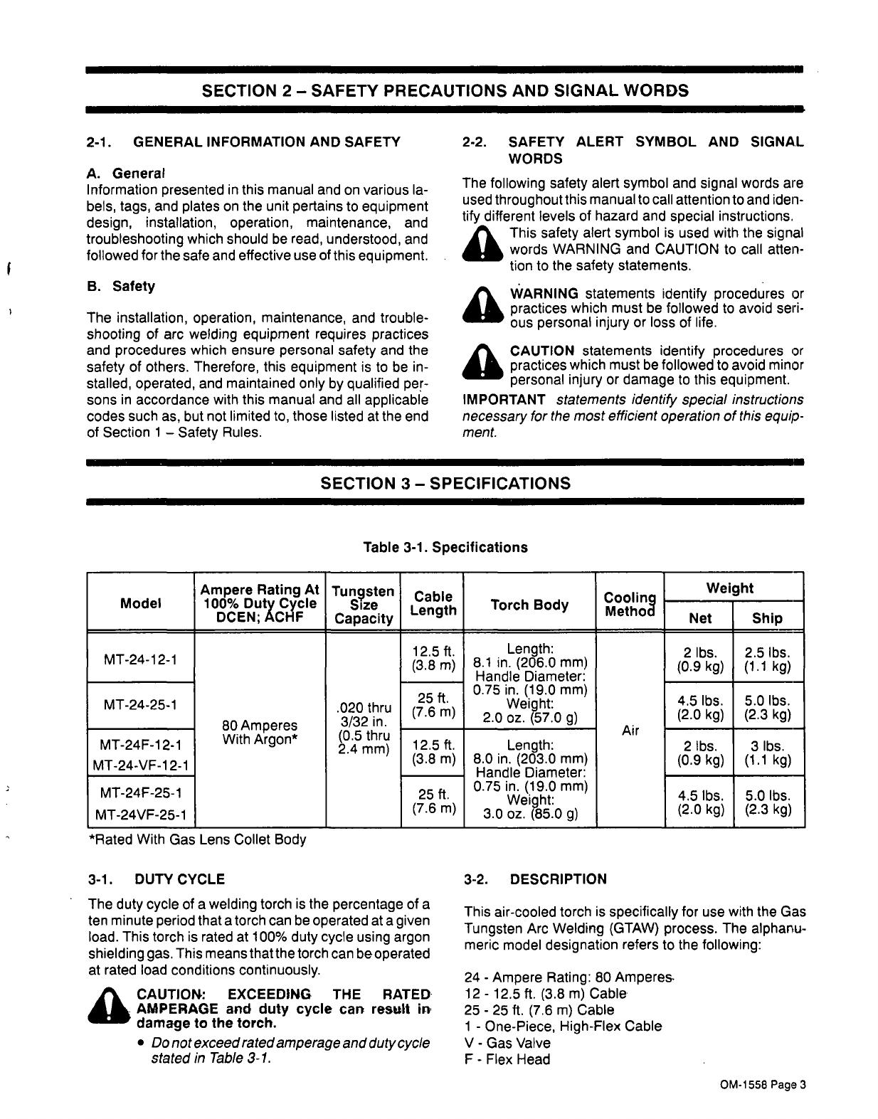
Table
3-1.
Specifications
Model
Ampere
Rating
At
100%
Duty
Cycle
DCEN;
ACHF
Tun9sten
Size
Capacity
Cable
Length
Torch
Body
Cooling
Method
Wei
ght
Net
Ship
MT-24-12-1
MT-24-25-1
MT-24F-1
2-1
MT-24-VF-12-1
MT-24F-25-1
MT-24VF-25-1
80
Amperes
With
Argon*
.020
thru
3/32
in.
(0.5
thru
2.4
mm)
12.5
ft.
(3.8
m)
25
ft
(7.6
m)
Length:
8.1
in.
(206.0
mm)
Handle
Diameter:
0.75
in.
(19.0
mm)
Weight:
2.0
oz.
(57.0
g)
Air
2
lbs.
(0.9
kg)
2.5
lbs.
(1.1
kg)
4.5
lbs.
(2.0
kg)
5.0
lbs.
(2.3
kg)
12.5
ft.
(3.8
m)
25
ft.
(7.6
m)
Length:
8.0
in.
(203.0
mm)
Handle
Diameter:
0.75
in.
(19.0
mm)
Weight:
3.0
oz.
(85.0
g)
2
lbs.
(0.9
kg)
3
lbs.
(1.1
kg)
4.5
lbs.
(2.0
kg)
5.0
lbs.
(2.3
kg)
*Rated
With
Gas
Lens
Collet
Body
3-1.
DUTY
CYCLE
The
duty
cycle
of
a
welding
torch
is
the
percentage
of
a
ten
minute
period
that
a
torch
can
be
operated
at
a
given
load.
This
torch
is
rated
at
100%
duty
cycle
using
argon
shielding
gas.
This
means
that
the
torch
can
beoperated
at
rated
load
conditions
continuously.
CAUTION:
EXCEEDING
THE
RATED
AMPERAGE
and
duty
cycle
can
result
in
damage
to
the
torch.
Do
not
exceed
rated
amperage
and
duty
cycle
stated
in
Table
3-1.
3-2.
DESCRIPTION
This
air-cooled
torch
is
specifically
for
use
with
the
Gas
Tungsten
Arc
Welding
(GTAW)
process.
The
alphanu
meric
model
designation
refers
to
the
following:
24
-
Ampere
Rating:
80
Amperes.
12-
12.5
ft.
(3.8
m)
Cable
25
-
25
ft.
(7.6
m)
Cable
1
-
One-Piece,
High-Flex
Cable
V
-
Gas
Valve
F
-
Flex
Head
a
OM-1
558
Page
3
SECTION
4
INSTALLATION
*Cup
~Tungsten
Electrode
Heat
Shield
Torch
Body
(Neck
Portion)
*POwer
Cable
Adapter
Gas
Valve
(If
Applicable)
0-Ring
Handle
>
SA-120
671
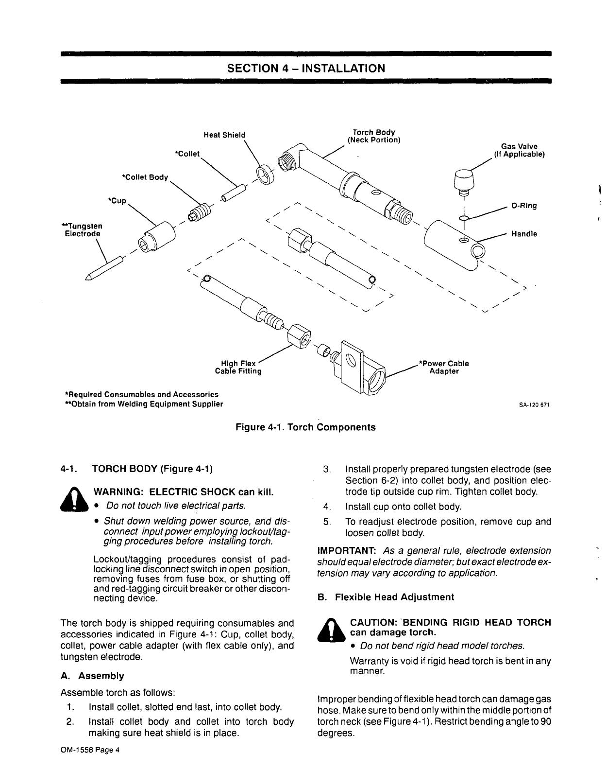
Figure
4-1.
Torch
Components
4-1.
TORCH
BODY
(Figure
4-1)
a
WARNING:
ELECTRIC
SHOCK
can
kill.
Do
not
touch
live
electrical
parts.
Shut
down
welding
power
source,
and
dis
connect
input
power
employing
lockout/tag
ging
procedures
before
installing
torch.
Lockoutltagging
procedures
consist
of
pad
locking
line
disconnect
switch
in
open
position,
removing
fuses
from
fuse
box,
or
shutting
off
and
red-tagging
circuit
breaker
or
other
discon
necting
device.
The
torch
body
is
shipped
requiring
consumables
and
accessories
indicated
in
Figure
4-1:
Cup,
collet
body,
collet,
power
cable
adapter
(with
flex
cable
only),
and
tungsten
electrode.
A.
Assembly
Assemble
torch
as
follows:
1.
Install
collet,
slotted
end
last,
into
collet
body.
2.
Install
collet
body
and
collet
into
torch
body
making
sure
heat
shield
is
in
place.
3.
Install
properly
prepared
tungsten
electrode
(see
Section
6-2)
into
collet
body,
and
position
elec
trode
tip
outside
cup
rim.
Tighten
collet
body.
4.
Install
cup
onto
collet
body.
5.
To
readjust
electrode
position,
remove
cup
and
loosen
collet
body.
IMPORTANT:
As
a
general
rule,
electrode
extension
should
equal
electrode
diameter;
but
exact
electrode
ex
tension
may
vary
according
to
application.
B.
Flexible
Head
Adjustment
a
CAUTION:
BENDING
RIGID
HEAD
TORCH
can
damage
torch.
Do
not
bend
rigid
head
model
torches.
Warranty
is
void
if
rigid
head
torch
is
bent
in
any
manner.
Improper
bending
of
flexible
head
torch
can
damage
gas
hose.
Make
sureto
bend
onlywithin
the
middle
portion
of
torch
neck
(see
Figure
4-1).
Restrict
bending
angle
to
90
degrees.
*Collet
*ColIet
Body
-~
High
Flex
Cable
Fitting
*Required
Consumables
and
Accessories
**Obtain
from
Welding
Equipment
Supplier
OM-1
558
Page
4

4-2.
GAS
HOSE
CONNECTIONS
AND
GAS
VALVE
(If
Applicable)
(Figures
4-1
Thru
4-3)
IMPORTANT:
lfpower
source
is
not
equipped
with
a
gas
valve,
a
torch
gas
valve
is
required
(see
Figure
4-2).
A.
High
Flex
Cable
Assembly
The
high
flex
cable
assembly
contains
the
power
cable
within
the
gas
hose.
The
high
flex
cable
has
a
3/8-24
fe
male
right-hand
fitting
(see
Figure
4-1).
Torch
To
install
high
flex
cable,
connect
high
flex
cable
fitting
to
power
cable
adapter.
If
torch
includes
a
gas
valve,
connect
a
suitable
length
of
gas
hose
(extra
hose
not
supplied)
from
power
cable
adapter
to
regulator/flowmeter
(see
Figure
4-2).
If
torch
is
without
gas
valve,
connect
a
suitable
length
of
gas
hose
(not
supplied)
from
power
cable
adapter
to
gas
valve
outlet.
Connect
extra
gas
hose
(not
supplied)
from
gas
valve
inlet
to
regulator/flowmeter
(see
Figure
4-3).
Torch
Work
Clamp
Figure
4-3.
GTAW
Torch
Connection
Diagram
For
Models
Without
Gas
Valve
Gas
Cylinder
Ref.
SA.120
909
Regulator!
Flowmeter
Work
Clamp
Power
Cable
Adapter
Figure
4-2.
GTAW
Torch
Connection
Diagram
For
Models
With
Gas
Valve
Rot.
SA.120
909
Power
Cable
Adapter
Gas
Valve
OM-1
558
Page
5
B.
Torch
Gas
Valve
Operation
(If
Applicable)
The
gas
valve
allows
gas
flow
control
at
the
torch.
A
one-
half
turn
counterclockwise
opens
the
gas
valve,
and
a
one-half
turn
clockwise
closes
the
valve.
The
gas
valve
allows
control
of
gas
postflow
time,
or
the
length
of
time
gas
flows
after
the
arc
is
extinguished.
In
sufficient
gas
postflow
results
in
an
oxidized
(black)
elec
trode
surface.
If
an
oxidized
electrode
were
used,
the
black
surface
would
contaminate
the
weld
and
cause
poor
arc
direction.
IMPORTANT:
As
a
general
rule,
allow
10
seconds
of
gas
postflow
time
per
100
amperes
of
weld
current
be
fore
closing
valve.
4-3.
POWER
CABLE
CONNECTION
(Figures
4-1
Thru
4-3)
a
WARNING:
ELECTRIC
SHOCK
can
kill.
Do
not
touch
live
electrical
parts.
Shut
down
welding
power
source,
and
dis
connect
in
put
power
employing
lockout/tag
ging
procedures
before
installing
torch.
Lockout/tagging
procedures
consist
of
pad
locking
line
disconnect
switch
in
open
position,
removing
fuses
from
fuse
box,
or
shutting
off
and
red-tagging
circuit
breaker
or
other
discon
necting
device.
The
power
cable
is
part
of
the
high
flex
cable
assembly.
For
connection
of
both
power
cable
and
gas
hose
to
power
cable
adapter,
see
Section
4-2A.
Connect
power
cable
adapter
to
weld
output
terminal
(see
Figures
4-2
and
4-3).
SECTION
5
SEQUENCE
OF
OPERATION
a
WARNING:
ELECTRIC
SHOCK
can
kill.
Do
not
touch
live
electrical
parts.
Keep
all
covers
and
handle
in
place
while
operating.
ARC
RAYS,
SPARKS,
AND
HOT
SURFACES
can
burn
eyes
and
skin;
NOISE
can
damage
hearing.
Wear
correct
eye,
ear,
and
body
protection.
FUMES
AND
GASES
can
seriously
harm
your
health.
Keep
your
head
out
of
the
fumes.
Ventilate
to
keep
from
breathing
fumes
and
gases.
If
ventilation
is
inadequate,
use
approved
breathing
device.
HOT
METAL,
SPATTER,
AND
SLAG
can
cause
fire
and
burns.
Watch
for
fire.
Keep
a
fire
extinguisher
nearby,
and
know
how
to
use
it.
Do
not
use
near
flammable
material.
Allow
work
and
equipment
to
cool
before
handling.
MAGNETIC
FIELDS
FROM
HIGH
CURRENTS
can
affect
pacemaker
operation.
Wearers
should
consult
their
doctor
before
going
near
arc
welding,
gouging,
or
spot
weld
ing
operations.
See
Section
1
-
Safety
Rules
for
additional
information.
5-1.
GAS
TUNGSTEN
ARC
WELDING
(GTAW)
1.
Install
and
connect
torch
according
to
Section
4.
2.
Make
sure
collet
body,
cup,
and
all
gas
connec
tions
are
securely
tightened.
3.
With
regulator/flowmeter
valve
closed,
open
gas
cylinder
valve.
4.
Set
power
source
for
desired
welding
amperage.
5.
Wear
dry
insulating
gloves
and
clothing,
and
wear
welding
helmet
with
proper
filter
lens
according
to
ANSI
Z49.1.
6.
Energize
welding
power
source.
7.
Set
gas
flow
to
desired
level
(requires
open
gas
valve).
IMPORTANT:
Purge
gas
hose
to
clear
hose
of
air,
mois
ture,
or
any
other
contaminants.
Allow
gas
to
flow
2
to
3
minutes
on
new
torch;
5
to
6
seconds
thereafter.
8.
Begin
welding.
5-2.
SHUTTING
DOWN
1.
Stopwelding.
IMPORTANT:
As
a
general
rule,
allow
10
seconds
of
gas
postflow
time
per
100
amperes
of
weld
current
be
fore
closing
valve.
2.
Turn
off
welding
power
source.
3.
Turn
off
the
shielding
gas
at
the
source.
a
WARNING:
HIGH
CONCENTRATION
OF
SHIELDING
GAS
can
harm
health
or
kill.
Shut
off
gas
supply
when
not
in
use.
OM-1558
Page
6

SECTION
6
MAINTENANCE
6-1.
ROUTINE
MAINTENANCE
(Table
6-1)
a
WARNING:
ELECTRIC
SHOCK
can
kill;
HOT
SURFACES
can
cause
severe
burns.
Do
not
touch
live
electrical
parts.
Shut
down
welding
power
source
and
discon
nect
input
power
before
working
on
torch.
Disconnect
torch
from
we/ding
power
source
before
inspecting,
maintaining,
or
servicing.
Allow
a
cooling
period
before
servicing.
Table
6-1.
Maintenance
Schedule
Frequency*
Maintenance
Every
Week
Inspect
and
clean
torch,
cables,
and
hoses
(see
Sections
6-IA
thru
6-iC).
Check
and
replace
torch
parts
or
weld
cables
as
necessary
(see
Sections
6-lA
thru
6-iC).
*Frequency
of
service
is
based
on
units
operated
40
hours
per
week.
Increase
frequency
of
maint
enance
if
usage
exceeds
40
hours
per
week.
A.
Inspection
And
Cleaning
a
WARNING:
Read
and
follow
safety
informa
tion
at
beginning
of
entire
Section
6-1
before
proceeding.
Inspect
torch
for
broken
areas,
cracks
and
loose
parts;
tighten,
repair
and
replace
as
required.
Remove
grease
and
dirt
from
components,
and
mois
ture
from
electrical
parts
and
cables.
B.
Torch
Body
a
WARNING:
Read
and
follow
safety
informa
tion
at
beginning
of
entire
Section
6-1
before
proceeding.
Once
a
week
inspect
condition
of
torch
body
compo
nents.
Replace
cup,
heat
shield,
arid
0-ring
if
cracked.
Main
tain
tight
fit
of
torch
components
to
ensure
good
weld
quality.
C.
Hoses,
Connections,
And
Cables
a
WARNING:
Read
and
follow
safety
informa
tion
at
beginning
of
entire
Section
6-1
before
proceeding.
Once
a
week
inspect
hoses
and
connections.
1.
Gas
Gas
leaks
may
result
in
poor
weld
quality.
Inspect
hoses
for
breaks.
Keep
connections
clean
and
tight.
2.
Power
Cable
Inspect
cables
for
breaks
in
insulation,
and
ensure
that
all
connections
are
clean
and
tight.
Repair
or
replace
cables
if
insulation
breaks
are
present.
Clean
and
tight
en
connections
at
each
inspection.
6-2.
TUNGSTEN
ELECTRODE
(Table
6-2
And
Figures
6-1
And
6-2)
Use
Table
6-2
to
select
the
correct
size
and
type
tung
sten
electrode.
Prepare
the
tungsten
electrode
using
the
following
guidelines.
A
properly
prepared
tungsten
elec
trode
is
essential
in
obtaining
a
satisfactory
weld.
A.
For
AC
or
DC
Electrode
Positive
Welding
(Figure
6-1)
Ball
the
end
of
tungsten
electrodes
used
for
ac
or
dc
electrode
positive
welding
before
beginning
the
welding
operation.
Weld
amperage
causes
the
tungsten
elec
trode
to
form
the
balled
end.
The
diameter
of
the
end
should
not
exceed
the
diameter
of
the
tungsten
elec
trode
by
more
than
1-1/2
times.
For
example,
the
end
of
a
1/8
in.
(3.2
mm)
diameter
tungsten
electrode
should
not
exceed
a
3/16
in.
(4.8
m)
diameter
end.
Figure
6-1.
Properly
Prepared
Tungsten
Electrodes
B.
For
DC
Electrode
Negative
Welding
(Figures
6-1
And
6-2)
a
CAUTION:
HOT
FLYING
METAL
PARTICLES
can
injure
personnel,
start
fires,
and
dam
age
equipment;
TUNGSTEN
CONTAMINA
TION
can
lower
weld
quality.
Shape
tungsten
electrode
only
on
grinder
with
proper
guards
in
a
safe
location
wearing
proper
face,
hand,
and
body
protection.
Do
not
use
same
wheel
for
any
other
job,
or
the
tungsten
will
become
contaminated.
Shape
tungsten
electrodes
on
a
fine
grit,
hard
abrasive
wheel
used
only
for
tungsten
shap
ing.
Grind
tungsten
electrodes
so
that
grind
ing
marks
run
lengthwise
with
the
electrode.
These
procedures
reduce
the
possibility
of
the
tungsten
electrode
transferring
foreign
matter
into
the
weld
and
help
reduce
arc
wander.
~
I-4-1-1/2
Times
I
Electrode
~
Diameter
I.
>J.
AC
And
DC
Electrode
Positive
A
]~_
2-1/2
Times
Electrode
Diameter
DC
Electrode
Negative
S-0161
OM-1
558
Page
7

Grind
the
end
of
the
tungsten
electrode
to
a
taper
for
a
distance
of
2
to
2-1/2
electrode
diameters
in
length.
For
example,
the
ground
surface
for
a
1/8
in.
(3.2
mm)
di
ameter
tungsten
electrode
should
be
1/4
to
5/16
in.
(6.4
to
8.0
mm)
long.
TUNGSTEN
PREPARATION:
IDEAL
Stable
Arc
Straight
~
Fiat
(The
Dia.
Of
This
Fiat
Governs
Amperage
Capacity)
For
additional
information,
see
your
distributor
for
a
handbook
on
the
Gas
Tungsten
Arc
Welding
(GTAW)
process.
TUNGSTEN
PREPARATiON:
WRONG
Arc
Wander
Point
S-0162
Figure
6-2.
Tungsten
Preparation
Table
6-2.
Tungsten
Size
Electrode
Diameter
Amperage
Range
-
Polarity
-
Gas
Type
Pure
Tungsten
(Green
Band)
DC-Argon
Electrode
Negative/Straight
Polarity
DC-Argon
Electrode
Positive/Reverse
Polarity
AC-Argon
Using
High
Frequency
AC-Argon
Balanced
Wave
Using
High
Freq.
.010
.020
Uptol5
5-20
*
*
Uptol5
5-20
UptolO
10-20
.040
15-80
*
10-60
20-30
1/16
70-150
10-20
50-100
30-80
3/32.
125-225
15-30
100-160 60-130
1/8
225-360
25-40
150-210
100-180
5/32
360-450
40-55
200-275
160-240
3/16
450-720
55-80
250-350
190-300
1/4
720-950
80-1
25
325-450 250-400
2%
ThorIum
Alloyed
Tungsten
(Red
Band)
.010
Upto25
*
Upto2O
Uptol5
.020
15-40
*
15-35
5-20
.040
25-85
*
20-80 20-60
1/16
50-160
10-20
50-150
60-120
3/32
135-235
15-30
130-250 100-180
1/8
250-400
25-40
225-360
160-250
5/32
400-500
40-55
300-450
200-320
3/16
500-750
55-80
400-500 290-390
1/4
750-1000
80-125
600-800
340-525
Zirconium
Alloyed
Tungsten
(Brown
Band)
.010
.020
.040
1/16
3/32
1/8
5/32
3/16
1/4
*
*
*
*
*
~
*
*
*
*
*
*
*
*
*
~
*
*
Upto2O
15-35
20-80
50-150
130-250
225-360
300-450
400-550
600-800
Uptol5
5-20
20-60
60-120
100-180
160-250
200-320
290-390
340-525
*NOT
RECOMMENDED
The
figures
listed
are
intended
as
a
guide
and
are
a
composite
of
recommendations
from
American
Welding
Society
(AWS)
and
electrode
manufacturers.
S-000gf888
Radial
Ground
OM-1558
PageS
Fig
7-2
2
1N>2
Figure
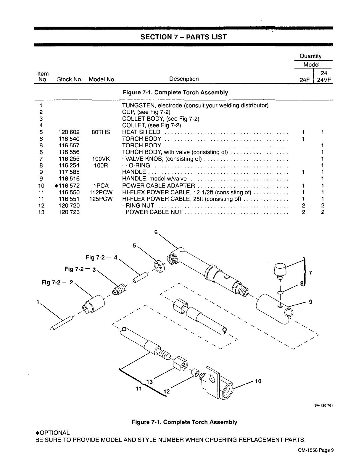
7-1.
Complete
Torch
Assembly
SA120
761
OPTIONAL
BE
SURE
TO
PROVIDE
MODEL
AND
STYLE
NUMBER
WHEN
ORDERING
REPLACEMENT
PARTS.
OM-1
558
Page
9
.
SECTION
7
PARTS
LIST
Quantity
Model
Item
24
No.
Stock
No.
Model
No.
Description
24F
24VF
Figure
7-1.
Complete
Torch
Assembly
1
2
3
4
5
120602
8OTHS
TUNGSTEN,
electrode
(consult
your
welding
distributor)
CUP,
(see
Fig
7-2)
COLLET
BODY,
(see
Fig
7-2)
COLLET,
(see
Fig
7-2)
HEAT
SHIELD
1 1
6
116540
TORCH
BODY
1
6
116557
TORCH
BODY
1
6
7
8
116
556
116
255
116254
100VK
100R
TORCH
BODY,
with
valve
(consisting
of)
VALVE
KNOB,
(consisting
of)
~0-RING
1
1
1
9
117585
HANDLE
1
1
9
118
516
HANDLE,
model
w/valve
1
10
116572
1PCA
POWERCABLEADAPTER
1
1
11
11
12
116
550
116
551
120720
112PCW
125PCW
HI-FLEX
POWER
CABLE,
12-1/2ft
(consisting
of)
HI-FLEX
POWER
CABLE,
25ft
(consisting
of)
.
RING
NUT
1
1
2
1
1
2
13
120
723
.
POWER
CABLE
NUT
2
2
5
Fig
7-2
4
Fig
7-2
3
7
9
>
11
10
CONSUMABLE
PARTS
SELECTOR
in
.020
.040
1/16
3/32
(mm)
(0.5)
(1.0)
(1.6)
(2.4)
ACHF
5-20
10-80
50-150
100-235
_____________
DCSP
5-20
15-80
70-150
150-250
ModelNo.
8C20
8C40
8C116
8C332
StockNo.
119419
119418
119417
119416
ModelNo.
8CB20
8CB40
8CB116
8CB332
Stock
No.
119883
119884
119885
119886
Stock/Model
No.
Cup
Orifice
Ceramic
Cup
119411
(8C1)
165
119410(8C4)
1/4
119
409
(8C5)
5/16
11940818C6)
3/8
Ceramic
Cup
~
119
421
(8C4L)
1/4
1
1/8
Long
119
420
(8C6L)
3/8
CROSS
REFERENCE
TO
COMPETITIVE
MODEL
STOCK
NO.
MODEL
NO.
COMPETITIVE
119419
8C20
53N15
119418
8C40
53N16
119417
8C116
53N14
119416
8C332
24C332
119883
8CB20
53N17
119884
8CB40
53N18
119885
8CB116
53N19
119886
8CB332
24CB332
119411
8C1
53N23
119410
8C4
53N24
119409
8C5
53N25
119408
8C6
53N27
119421
.8C4L
53N28
119420
8C6L
53N26
Shaded
Areas
Indicate
Recommended
Usage
Ga.
Len.
Ga~
lena
Collat
Collat
Body
8CG
Sane,
2GL
Sari.,
Use
8G1IS
heat
shield
Stock
No.
119
887
For
Gas
Lens
Alumina
Cup
1
Long
~
Stock/Model
No.
Cup
Orifice
119
893
(2AG4)
1/4
119
894
(2AG5)
5/16
119
895
(2AG6)
3/8
119896(2AG7)
7/16
CROSS
REFERENCE
TO
COMPETITIVE
MODEL
STOCK
NO.
MODEL
NO.
COMPETITIVE
120
231
8CG20
53N62
120232
8CG40
53N63
120233
8CG116
53N64
120
234
8CG332
24GLC332
119897
2GL20
45V41
119
898
2GL40
45V42
119899
2GL116
45V43
119900
2GL332
45V44
119893
2AG4
53N58
119894
2AG5
53N59
119895
2AG6
53N60
119896
2AG7
53N61
Tungsten
Diameter
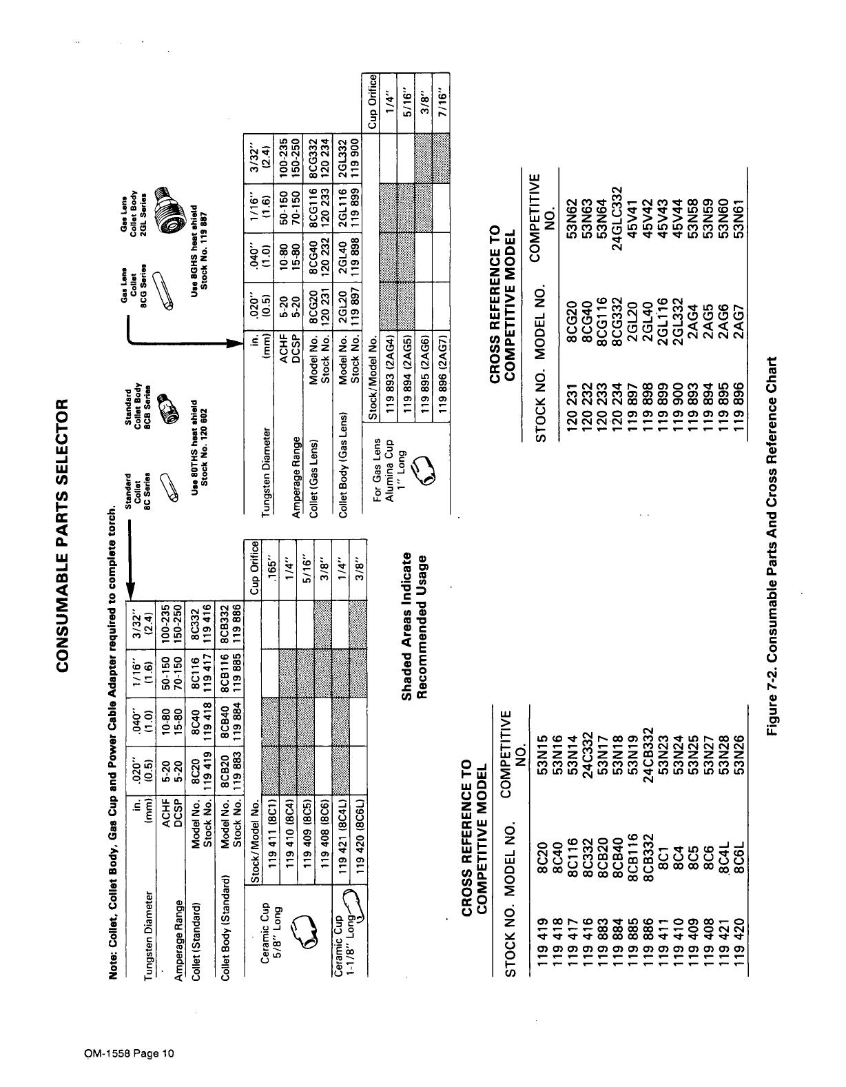
Note:
Collet.
Collet
Body,
Gas
Cup
and
Power
Cable
Adapter
required
to
complete
torch.
Amperage
Range
Collet
(Standard)
Collet
Body
(Standard)
Standard
Collet
8C
Series
Standard
Coliat
Body
8C8
Sari..
U.e
BaTHS
heat
shield
Stock
No.
120
602
Tungsten
Diameter
Amperage
Range
Collet
(Gas
Lens)
Collet
Body
(Gas
Lens)
in
.020
.040
1/16
3/32
(mm)
(0.5)
(1.0)
(1.6)
(2.4)
ACHF
5-20
10-80
50-150
100-235
DCSP
5-20
15-80
70-150
150-250
ModelNo.
8CG20
8CG40
8CG116
8CG332
Stock
No.
120
231
120
232
120
233
120
234
ModelNo.
2GL20
2GL40
2GL116
2GL332
Stock
No.
119897
119898
119899
119900
Figure
7-2.
Consumable
Parts
And
Cross
Reference
Chart

OPTIONS
AND
ACCESSORIES
POWER
CABLE
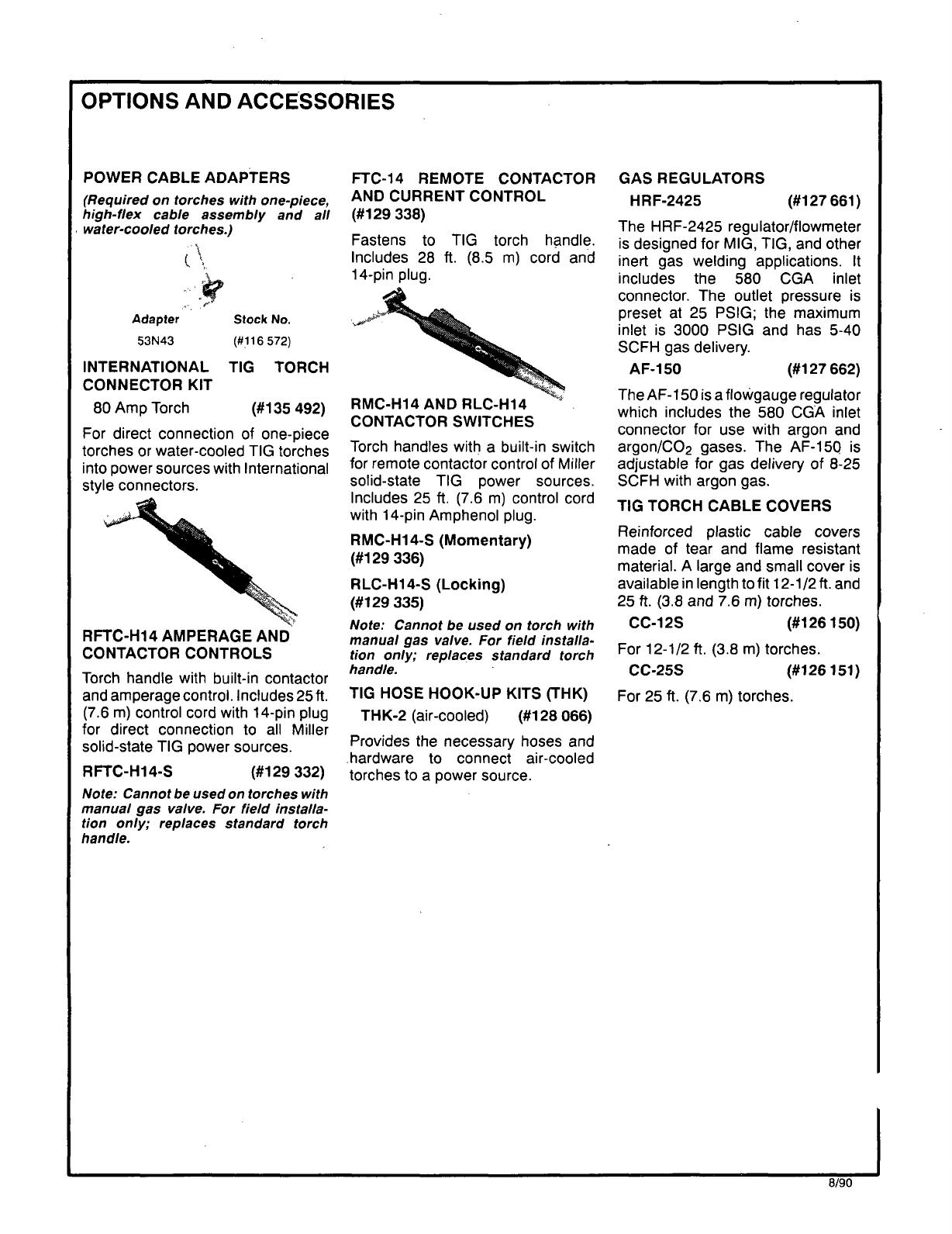
ADAPTERS
(Required
on
torches
with
one-piece,
high-flex
cable
assembly
and
all
water-cooled
torches.)
Adapter
53N43
:q
Stock
No.
(#116
572)
INTERNATIONAL
TIG
TORCH
CONNECTOR
KIT
80
Amp
Torch
(#135
492)
For
direct
connection
of
one-piece
torches
or
water-cooled
TIG
torches
into
power
sources
with
International
style
connectors.
Torch
handle
with
built-in
contactor
and
amperage
control.
Includes
25
ft.
(7.6
m)
control
cord
with
14-pin
plug
for
direct
connection
to
all
Miller
solid-state
TIG
power
sources.
RFTC-H14-S
(#129
332)
Note:
Cannot
be
used
on
torches
with
manual
gas
valve.
For
field
installa
tion
only;
replaces
standard
torch
handle.
FTC-14
REMOTE
CONTACTOR
AND
CURRENT
CONTROL
(#129
338)
Fastens
to
TIG
torch
handle.
Includes
28
ft.
(8.5
m)
cord
and
14-pin
plug.
Torch
handles
with
a
built-in
switch
for
remote
contactor
control
of
Miller
solid-state
TIG
power
sources.
Includes
25
ft.
(7.6
m)
control
cord
with
14-pin
Amphenol
plug.
RMC-H14-S
(Momentary)
(#129
336)
RLC-H14-S
(Locking)
(#129
335)
Note:
Cannot
be
used
on
torch
with
manual
gas
valve.
For
field
installa
tion
only;
replaces
standard
torch
handle.
TIG
HOSE
HOOK-UP
KITS
(THK)
THK-2
(air-cooled)
(#128
066)
Provides
the
necessary
hoses
and
hardware
to
connect
air-cooled
torches
to
a
power
source.
GAS
REGULATORS
HRF-2425
(#127
661)
The
HRF-2425
regulator/flowmeter
is
designed
for
MIG,
TIC,
and
other
inert
gas
welding
applications.
It
includes
the
580
CGA
inlet
connector.
The
outlet
pressure
is
preset
at
25
PSIG;
the
maximum
inlet
is
3000
PSIG
and
has
5-40
SCFH
gas
delivery.
AF-150
(#127
662)
The
AF-
150
is
a
flowgauge
regulator
which
includes
the
580
CGA
inlet
connector
for
use
with
argon
and
argon/CO2
gases.
The
AF-150
is
adjustable
for
gas
delivery
of
8-25
SCFH
with
argon
gas.
TIG
TORCH
CABLE
COVERS
Reinforced
plastic
cable
covers
made
of
tear
and
flame
resistant
material.
A
large
and
small
cover
is
available
in
length
to
fit
12-1/2
ft.
and
25
ft.
(3.8
and
7.6
m)
torches.
CC-i
2S
(#126
150)
For
12-1/2
ft.
(3.8
m)
torches.
CC-25S
For
25
ft.
(7.6
m)
torches.
(#126
151)
RMC-H14
AND
RLC-Hi4
CONTACTOR
SWITCHES
RFTC-H14
AMPERAGE
AND
CONTACTOR
CONTROLS
8/90
/