Abit AX8 Series Owner's manual
- Category
- Motherboards
- Type
- Owner's manual
This manual is also suitable for

AX8 Series
(AX8-3
rd
Eye/AX8/AX8-V)
AMD Athlon 64
(FX) System Board
Socket 939
User’s Manual
4200-0431-01
Rev. 1.00

Copyright and Warranty Notice
The information in this document is subject to change without notice and does not
represent a commitment on part of the vendor, who assumes no liability or
responsibility for any errors that may appear in this manual.
No warranty or representation, either expressed or implied, is made with respect to the
quality, accuracy or fitness for any particular part of this document. In no event shall
the manufacturer be liable for direct, indirect, special, incidental or consequential
damages arising from any defect or error in this manual or product.
Product names appearing in this manual are for identification purpose only and
trademarks and product names or brand names appearing in this document are the
property of their respective owners.
This document contains materials protected under International Copyright Laws. All
rights reserved. No part of this manual may be reproduced, transmitted or transcribed
without the expressed written permission of the manufacturer and authors of this
manual.
If you do not properly set the motherboard settings, causing the motherboard to
malfunction or fail, we cannot guarantee any responsibility.
AX8 Series

Table of Contents
Chapter 1. Introduction .......................................................................... 1-1
1-1. Features & Specifications ........................................................................1-1
1-2. Layout Diagram .......................................................................................1-3
Chapter 2. Hardware Setup.................................................................... 2-1
2-1. Install The Motherboard...........................................................................2-1
2-2. Install CPU and Heatsink.........................................................................2-2
2-3. Install System Memory ............................................................................2-3
2-4. Connectors, Headers and Switches ..........................................................2-5
(1). ATX Power Input Connectors........................................................2-5
(2). FAN Power Connectors .................................................................2-6
(3). CMOS Memory Clearing Header ..................................................2-7
(4). Wake-up Header.............................................................................2-8
(5). Front Panel Switches & Indicators Headers ..................................2-9
(6). Additional USB Port Headers......................................................2-10
(7). Additional IEEE1394 Port Headers (AX8-3
rd
Eye/AX8)..............2-11
(8). Front Panel Audio Connection Header ........................................2-12
(9). Internal Audio Connectors ...........................................................2-13
(10). GURU Clock Connection Header................................................2-13
(11). PCI Express x16 Slot ...................................................................2-14
(12). PCI Express x1 Slots....................................................................2-14
(13). Floppy and IDE Disk Drive Connectors......................................2-15
(14). POST Code Display.....................................................................2-16
(15). Serial ATA Connectors .................................................................2-17
(16). Status Indicators...........................................................................2-17
(17). Back Panel Connectors ................................................................2-18
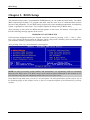
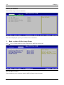
Chapter 3. BIOS Setup............................................................................ 3-1
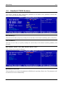
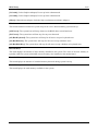
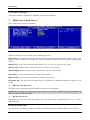
3-1. µGuru Utility............................................................................................3-2
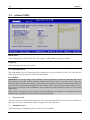
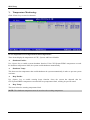
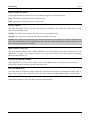
3-2. Standard CMOS Features.........................................................................3-9
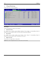
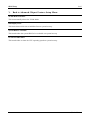
3-3. Advanced BIOS Features.......................................................................3-12
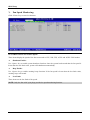
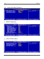
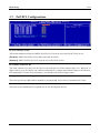
3-4. Advanced Chipset Features....................................................................3-14
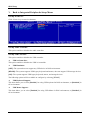
3-5. Integrated Peripherals ............................................................................3-16
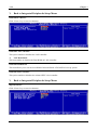
3-6. Power Management Setup .....................................................................3-20
3-7. PnP/PCI Configurations.........................................................................3-23
3-8. Load Fail-Safe Defaults .........................................................................3-24
User’s Manual

3-9. Load Optimized Defaults .......................................................................3-24
3-10. Set Password ..........................................................................................3-24
3-11. Save & Exit Setup ..................................................................................3-24
3-12. Exit Without Saving...............................................................................3-24
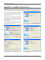
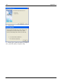
Appendix A. Install VIA 4-in-1 Driver ................................................................. A-1
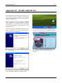
Appendix B. Install Audio Driver ......................................................................... B-1
Appendix C. Install LAN Driver ........................................................................... C-1
Appendix D. Install VIA USB 2.0 Driver .............................................................D-1
Appendix E. Install VIA South Bridge SATA RAID Driver ............................... E-1
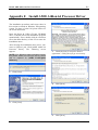
Appendix F. Install AMD Athlon 64 Processor Driver ....................................... F-1
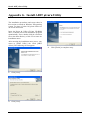
Appendix G. Install ABIT µGuru Utility ..............................................................G-1
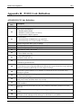
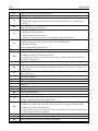
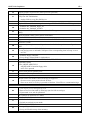
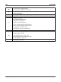
Appendix H. POST Code Definition .....................................................................H-1
Appendix I. Troubleshooting (Need Assistance?)................................................ I-1
Appendix J. How to Get Technical Support .........................................................J-1
AX8 Series

Introduction 1-1
Chapter 1. Introduction
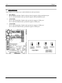
1-1. Features & Specifications
1. CPU
• Supports AMD Socket 939 Athlon 64/64FX Processor with 2GHz system bus using Hyper
Transport
™
Technology
• Supports AMD K8 CPU Cool ‘n’ Quiet Technology
2. Chipset
• VIA K8T890 + VT8237
3. CPU Integrated Dual Channel Memory Controller
• Four 184-pin DIMM slots (Un-buffered, Non-ECC DIMM)
• Supports 2 DIMM Single Channel DDR 400/333/266 (Max. 2GB)
• Supports 4 DIMM Dual Channel DDR 400/333/266 (Max. 4GB)
4. PCI Express X16 Graphics
• PCI Express X16 graphics delivers up to 8GB/s bandwidth
5. SATA RAID
• Supports SATA RAID 0/1 (Connectors SATA1~SATA2)
6. Second SATA RAID (AX8-3
rd
Eye/AX8)
• Supports SATA RAID 0/1 (Connectors SATA3~SATA4)
• Supports SATA RAID 0/1/0+1 (Connectors SATA1~SATA4)
• Supports RAID 0/1/JBOD (Connector IDE3)
• Supports RAID JBOD (Connectors SATA1~SATA4 and IDE3)
7. Gigabit LAN
• Onboard Gigabit PCI Ethernet Controller
8. IEEE 1394
• Supports IEEE 1394 at 100/200/400 Mb/s transfer rate (AX8-3
rd
Eye/AX8)
9. Audio
• Onboard 5.1-channel Audio CODEC
• Optical S/PDIF Input/Output (AX8-3
rd
Eye/AX8)
10. ABIT Engineered
• ABIT µGuru
™
Technology
• ABIT GuruClock
™
Technology (AX8-3
rd
Eye)
• ABIT CPU ThermalGuard
™
Technology
User’s Manual

1-2 Chapter 1
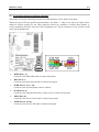
11. Internal I/O Connectors
• 1x PCI Express x16 slot
• 3x PCI Express x1 slots
• 2x PCI slots
• 1x Floppy port supports up to 2.88MB
• 2x Ultra DMA 33/66/100/133 connectors (AX8-V)
• 3x Ultra DMA 33/66/100/133 connectors (AX8-3
rd
Eye/AX8)
• 4x SATA 150 Connectors (AX8-3
rd
Eye/AX8)
• 2x SATA 150 Connectors (AX8-V)
• 2x USB 2.0 headers
• 1x IEEE 1394 header (AX8-3
rd
Eye/AX8)
• 1x FP-Audio header
• 1x CD-IN header
12. Back Panel I/O
• 1x PS/2 keyboard, 1x PS/2 mouse
• 1x Serial port connector, 1x Parallel port connector
• 1x S/PDIF In connector (AX8-3
rd
Eye/AX8)
• 1x S/PDIF Out connector (AX8-3
rd
Eye/AX8)
• 1x AUDIO1 connector (Rear-Left / Rear-Right, Center/Subwoofer)
• 1x AUDIO2 connector (Mic-In, Line-In, Front-Left/Front-Right)
• 4x USB 2.0 Connectors
• 1x IEEE 1394 Connector (AX8-3
rd
Eye/AX8)
• 1x RJ-45 LAN Connector
13. Miscellaneous
• ATX form factor: 305 x 245 mm
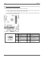
14. Order Information
Model Features
AX8-3
rd
Eye
4x SATA RAID 0/1/0+1 ports, 3x PATA ports, IEEE1394, S/PDIF,
GuruClock
AX8 4x SATA RAID 0/1/0+1 ports, 3x PATA ports, IEEE1394, S/PDIF
AX8-V 2x SATA RAID 0/1 ports, 2x PATA ports
Specifications and information contained herein are subject to change without notice.
AX8 Series

Introduction 1-3
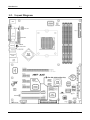
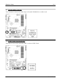
1-2. Layout Diagram
User’s Manual

1-4 Chapter 1
AX8 Series

Hardware Setup 2-1
Chapter 2. Hardware Setup
Before the Installation: Turn off the power supply switch (fully turn off the +5V standby power), or
disconnect the power cord before installing or unplugging any connectors or add-on cards. Failing to do
so may cause the motherboard components or add-on cards to malfunction or damaged.
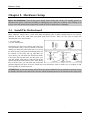
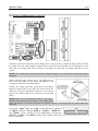
2-1. Install The Motherboard
Most computer chassis have a base with many mounting holes to allow motherboard to be securely
attached on and at the same time, prevented from short circuits. There are two ways to attach the
motherboard to the chassis base:
1. use with studs
2. or use with spacers
In principle, the best way to attach the board is to
use with studs. Only if you are unable to do this
should you attach the board with spacers. Line up
the holes on the board with the mounting holes on
the chassis. If the holes line up and there are
screw holes, you can attach the board with studs.
If the holes line up and there are only slots, you
can only attach with spacers. Take the tip of the
spacers and insert them into the slots. After doing
this to all the slots, you can slide the board into
position aligned with slots. After the board has been positioned, check to make sure everything is OK
before putting the chassis back on.
ATTENTION: To prevent shorting the PCB circuit, please REMOVE the metal studs or spacers if they
are already fastened on the chassis base and are without mounting-holes on the motherboard to align with.
User’s Manual

2-2 Chapter 2
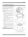
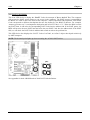
2-2. Install CPU and Heatsink
This motherboard provides a ZIF (Zero Insertion
Force) Socket 939 to install AMD Socket 939
CPU. The CPU you bought should contain with a
kit of heatsink, cooling fan, retention frame and
blackplate. If that’s not the case, buy one specially
designed for Socket 939.
Please refer to the figure shown here to install
CPU and heatsink. (For reference only. Your
Heatsink & Fan Assembly may not be exactly the
same as this one.)
1. Locate the Socket 939 on this motherboard.
Pull the CPU release lever sideways to
unlatch and then raise it all the way up.
2. Drop the processor with its pin side down into
the CPU socket. Do not use extra force to
insert CPU; it only fits in one direction. Close
the CPU release lever.
3. Align the Backplate Standoffs with the
mounting holes on motherboard. Position the
backplate onto motherboard.
4. Place the Retention Frame onto the
motherboard and align it with the Backplate
Standoffs.
5. Place heatsink on top of CPU, and make sure
the heatsink fits properly on the retention
frame.
6. Hook both sides of the Spring Clip onto the
Mounting Tabs of Retention Frame. Tighten
screws until the Spring Clip is fully installed.
7. Attach the fan connector of Heatsink & Fan
Assembly with the CPU-FAN connector on
the motherboard.
ATTENTION: Do not forget to set the correct
bus frequency and multiple for your processor.
AX8 Series

Hardware Setup 2-3
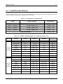
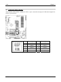
2-3. Install System Memory
This motherboard provides four 184-pin DDR DIMM slots for Single/Dual Channel DDR 400/333/266
memory modules with memory expansion size up to 4GB.
Table 2-1. Valid Memory Configurations
Bank Memory Module Total Memory
Bank 0, 1 (DIMM1) 256MB, 512MB, 1GB 256MB ~ 1GB
Bank 2, 3 (DIMM2) 256MB, 512MB, 1GB 256MB ~ 1GB
Bank 4, 5 (DIMM3) 256MB, 512MB, 1GB 256MB ~ 1GB
Bank 6, 7 (DIMM4) 256MB, 512MB, 1GB 256MB ~ 1GB
Total System Memory 256MB ~ 4GB
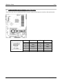
Table 2-2. Unbuffered DIMM Support For AMD 939-pin Processor
Data Bus DIMM1 DIMM2 DIMM3 DIMM4
Maximum
DRAM Speed
Single rank N/A Empty N/A DDR400
Double rank N/A Empty N/A DDR400
Empty N/A Single rank N/A DDR400
Empty N/A Double rank N/A DDR400
Single rank N/A Single rank N/A DDR400
Single rank N/A Double rank N/A DDR400
Double rank N/A Single rank N/A DDR400
64-bits
(Single
Channel)
Double rank N/A Double rank N/A DDR333
Single rank Single rank Empty Empty DDR400
Double rank Double rank Empty Empty DDR400
Empty Empty Single rank Single rank DDR400
Empty Empty Double rank Double rank DDR400
Single rank Single rank Single rank Single rank DDR400
Single rank Single rank Double rank Double rank DDR400
Double rank Double rank Single rank Single rank DDR400
128-bits
(Dual
Channel)
Double rank Double rank Double rank Double rank DDR333
User’s Manual

2-4 Chapter 2
To reach the performance of Dual Channel DDR, the following rules must be obeyed:
• When installing TWO DIMM modules: Install DIMM modules of the same type and size for
slots [DIMM1]+[DIMM2] or slots [DIMM3]+[DIMM4].
• When installing FOUR DIMM modules: Install DIMM modules of the same type and size for
slots [DIMM1]+[DIMM2], and slots [DIMM3]+[DIMM4].
NOTE: Usually there is no hardware or BIOS setup requires after adding or removing memory modules,
but you will have to clear the CMOS memory first if any memory module related problem occurs.
Power off the computer and unplug the AC power cord before installing or removing memory modules.
1. Locate the DIMM slot on the board.
2. Hold two edges of the DIMM module
carefully, keep away of touching its
connectors.
3. Align the notch key on the module with the
rib on the slot.
4. Firmly press the module into the slots until
the ejector tabs at both sides of the slot
automatically snaps into the mounting notch.
Do not force the DIMM module in with extra
force as the DIMM module only fit in one direction.
5. To remove the DIMM modules, push the two ejector tabs on the slot outward simultaneously, and
then pull out the DIMM module.
ATTENTION: Static electricity can damage the electronic components of the computer or optional
boards. Before starting these procedures, ensure that you are discharged of static electricity by touching a
grounded metal object briefly.
AX8 Series

Hardware Setup 2-5
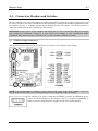
2-4. Connectors, Headers and Switches
Here we will show you all of the connectors, headers and switches, and how to connect them. Please read
the entire section for necessary information before attempting to finish all the hardware installation inside
the computer chassis. A complete enlarged layout diagram is shown in Chapter 1 for all the position of
connectors and headers on the board that you may refer to.
WARNING: Always power off the computer and unplug the AC power cord before adding or removing
any peripheral or component. Failing to so may cause severe damage to your motherboard and/or
peripherals. Plug in the AC power cord only after you have carefully checked everything.
ATX Power Input Connectors
(1).
This motherboard provides two power connectors to connect to an ATX12V power supply.
NOTE: It is recommended to connect to a power supply with 350W, 20A +5VDC capacity at least for
heavily loaded system, and a 2A +5VSB capacity at least for supporting wake-up features.
The auxiliary 12V power connector [POWER1]
p
rovides an additional power
source for devices added on PCI Express slots. It is highly recommended to
attach 12V power from the power supplier for the best system stability.
User’s Manual

2-6 Chapter 2
(2). FAN Power Connectors
These connectors each provide power to the cooling fans installed in your system.
• CPUFAN1: CPU Fan Power Connector
• NBFAN1: Chipset Fan Power Connector
• SYSFAN1: System Fan Power Connector
• AUXFAN1: Auxiliary Fan Power Connector
WARNING: These fan connectors are not jumpers. DO NOT place jumper caps on these connectors.
AX8 Series

Hardware Setup 2-7
(3). CMOS Memory Clearing Header
This header uses a jumper cap to clear the CMOS memory.
• Pin 1-2 shorted (default): Normal operation.
• Pin 2-3 shorted: Clear CMOS memory.
WARNING: Turn the power off first (including the +5V standby power) before clearing the CMOS
memory. Failing to do so may cause your system to work abnormally or malfunction.
User’s Manual

2-8 Chapter 2
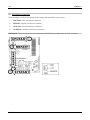
(4). Wake-up Header
These headers use a jumper cap to enable/disable the wake-up function.
• PS2-PWR1:
Pin 2-3 shorted (default): Enable wake-up function support at Keyboard/Mouse port.
Pin 1-2 shorted: Disable wake-up function support at Keyboard/Mouse port.
• USB-PWR1:
Pin 2-3 shorted (default): Enable wake-up function support at USB1 port.
Pin 1-2 shorted: Disable wake-up function support at USB1 port.
• USB-PWR2:
Pin 2-3 shorted (default): Enable wake-up function support at USB2 port.
Pin 1-2 shorted: Disable wake-up function support at USB2 port.
AX8 Series

Hardware Setup 2-9
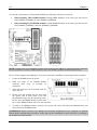
(5). Front Panel Switches & Indicators Headers
This header is used for connecting switches and LED indicators on the chassis front panel.
Watch the power LED pin position and orientation. The mark “+” align to the pin in the figure below
stands for positive polarity for the LED connection. Please pay attention to connect these headers. A
wrong orientation will only cause the LED not lighting, but a wrong connection of the switches could
cause system malfunction.
• HLED (Pin 1, 3):
Connects to the HDD LED cable of chassis front panel.
• RST (Pin 5, 7):
Connects to the Reset Switch cable of chassis front panel.
• SPKR (Pin 13, 15, 17, 19):
Connects to the System Speaker cable of chassis.
• SLED (Pin 2, 4):
Connects to the Suspend LED cable (if there is one) of chassis front panel.
• PWR (Pin 6, 8):
Connects to the Power Switch cable of chassis front panel.
• PLED (Pin 16, 18, 20):
Connects to the Power LED cable of chassis front panel.
User’s Manual

2-10 Chapter 2
(6). Additional USB Port Headers
These headers each provide 2 additional USB 2.0 ports connection through an USB cable designed for
USB 2.0 specifications.
Pin Pin Assignment Pin Pin Assignment
1 VCC 2 VCC
3 - Data 0 4 - Data 1
5 + Data 0 6 + Data 1
7 Ground 8 Ground
10 NC
AX8 Series

Hardware Setup 2-11
Additional IEEE1394 Port Headers (AX8-3
rd
Eye/AX8) (7).
This header provides one additional IEEE1394 port connection through an extension cable and bracket.
Pin Pin Assignment Pin Pin Assignment
1 TPA0 + 2 TPA0 -
3 GND 4 GND
5 TPB0 + 6 TPB0 -
7 +12V 8 +12V
9 NC 10 GND
User’s Manual

2-12 Chapter 2
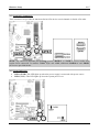
(8). Front Panel Audio Connection Header
This header provides the connection to audio connector at front panel.
• To use the audio connector at front panel, remove all the jumpers on this header, and then connect
to front panel by the extension cable provided with the chassis.
• To use the audio connector at rear panel, disconnect the extension cable, attach the jumpers back at
pin 5-6, and pin 9-10 (default setting).
Pin Pin Assignment Pin Pin Assignment
1 Audio Mic. 2 Ground
3 Audio Mic. Bias 4 VCC
5
Speaker Out Right
Channel
6
Speaker Out Right
Channel Return
7 X 8 NC
9
Speaker Out Left
Channel
10
Speaker Out Left
Channel Return
AX8 Series
Page is loading ...
Page is loading ...
Page is loading ...
Page is loading ...
Page is loading ...
Page is loading ...
Page is loading ...
Page is loading ...
Page is loading ...
Page is loading ...
Page is loading ...
Page is loading ...
Page is loading ...
Page is loading ...
Page is loading ...
Page is loading ...
Page is loading ...
Page is loading ...
Page is loading ...
Page is loading ...
Page is loading ...
Page is loading ...
Page is loading ...
Page is loading ...
Page is loading ...
Page is loading ...
Page is loading ...
Page is loading ...
Page is loading ...
Page is loading ...
Page is loading ...
Page is loading ...
Page is loading ...
Page is loading ...
Page is loading ...
Page is loading ...
Page is loading ...
Page is loading ...
Page is loading ...
Page is loading ...
Page is loading ...
Page is loading ...
Page is loading ...
Page is loading ...
Page is loading ...
Page is loading ...
Page is loading ...
Page is loading ...
Page is loading ...
Page is loading ...
Page is loading ...
Page is loading ...
Page is loading ...
Page is loading ...
Page is loading ...
Page is loading ...
Page is loading ...
Page is loading ...
Page is loading ...
Page is loading ...
-
 1
1
-
 2
2
-
 3
3
-
 4
4
-
 5
5
-
 6
6
-
 7
7
-
 8
8
-
 9
9
-
 10
10
-
 11
11
-
 12
12
-
 13
13
-
 14
14
-
 15
15
-
 16
16
-
 17
17
-
 18
18
-
 19
19
-
 20
20
-
 21
21
-
 22
22
-
 23
23
-
 24
24
-
 25
25
-
 26
26
-
 27
27
-
 28
28
-
 29
29
-
 30
30
-
 31
31
-
 32
32
-
 33
33
-
 34
34
-
 35
35
-
 36
36
-
 37
37
-
 38
38
-
 39
39
-
 40
40
-
 41
41
-
 42
42
-
 43
43
-
 44
44
-
 45
45
-
 46
46
-
 47
47
-
 48
48
-
 49
49
-
 50
50
-
 51
51
-
 52
52
-
 53
53
-
 54
54
-
 55
55
-
 56
56
-
 57
57
-
 58
58
-
 59
59
-
 60
60
-
 61
61
-
 62
62
-
 63
63
-
 64
64
-
 65
65
-
 66
66
-
 67
67
-
 68
68
-
 69
69
-
 70
70
-
 71
71
-
 72
72
-
 73
73
-
 74
74
-
 75
75
-
 76
76
-
 77
77
-
 78
78
-
 79
79
-
 80
80


Abit AX8 Series Owner's manual
- Category
- Motherboards
- Type
- Owner's manual
- This manual is also suitable for
Ask a question and I''ll find the answer in the document
Finding information in a document is now easier with AI
Related papers
Other documents
-
Gigabyte Superb 550P User manual
-
SPARKLE GEFORCE 210 SXG210256D2L-NM - PCI User manual
-
BCM BC845DL User's Quick Start Card
-
HP Brio 83xx Online Manual
-
Dynex DX-FC202 User manual
-
Kmart 43191062 User manual
-
ECS RD480-A939 User manual
-
Foxconn NF4XK8MC User manual
-
-
Albatron K8X890 Series User manual