Page is loading ...

Instruction handbook
Washer-extractors
WS4250H – WS4350H – WS4500H – WS4650H
WSB4250H – WSB4350H – WSB4500H – WSB4650H
01201138/GB
14.10

.

0907
0
0
Notice
Date
Page
01201138
INSTRUCTION
HANDBOOK
General instructions
General ................................................... 1/1
Precautions for use ................................. 1/2
Environmental information ...................... 1/3
Preliminary instructions ........................... 1/4
Locking and tagging procedure .............. 1/5
Handling/Weight
Handling .................................................. 1/6
Packing - Weight ..................................... 1/7
Technical characteristics
Technical characteristics ......................... 1/8
Sound level ............................................ 17/8
Label of energetic performances ........... 17/8
Installation/Putting into service
Installation ............................................... 1/9
Working place lighting ............................. 2/9
Supplies .................................................. 2/9
Mechanical installation ............................ 3/9
Fitting of the safety fl anges ..................... 4/9
Fitting of the fi lling angles ....................... 5/9
Assembling of the partition for
barrier machine ....................................... 6/9
Water connections .................................. 7/9
Steam connection ................................... 8/9
Indirect steam heating .............................. 9/9
Drain connection .................................... 10/9
Air vent connection ................................ 11/9
Installation of the gas exchanger ........... 11/9
Connection of the evacuation pipe of
the gas exchanger ................................. 13/9
Gas connection ...................................... 15/9
Liquid detergents connection ................. 22/9
Electrical connection .............................. 25/9
Remove of the transport locks fi tted ...... 30/9
Operating inspection
Manual operation ................................... 1/10
Automatic operation ............................... 2/10
Machine operation
Auxiliary control .................................... 1/11
Automatic operation ............................... 3/11
Detergent dispenser .............................. 5/11
To run a wash program .......................... 6/11
The "move back" key ............................. 6/11
To start the wash program ..................... 7/11
To start a wash program from the
program library ...................................... 10/11
To change parameters in the current
program step ......................................... 13/11
Pages/Chapters
The manufacturer reserves the right to modify construction and equipment characteristics.
Table of contents
Pages/Chapters
Rapid advance ...................................... 14/11
Show weight ......................................... 15/11
Pause .................................................... 17/11
Manual operation during a program ...... 18/11
Text ....................................................... 24/11
To change the wash program after
program operation has commenced ..... 25/11
To change temperature scale °C/ °F ..... 26/11
Auto restart ........................................... 27/11
Manual operation
To select a manual operation ................ 28/11
Motor/door ............................................ 29/11
Water/drain ........................................... 30/11
Heating ................................................. 31/11
Detergent signals and water fl ushing .... 32/11
At the end of the wash .......................... 33/11
Statistics
To select "statistics" .............................. 35/11
Resetting statistic registers ................... 37/11
Automatic weighing
Scale adjustments ................................ 42/11
ON/OFF and pause
On/off and pause by exterior signals .... 53/11
Memory card
General introduction ............................. 54/11
To select the "Memory card" function .... 55/11
To run a wash program straight from
a memory card ..................................... 58/11
To copy a program from a memory card
to the machine's program control unit ... 59/11
To copy a program from the program
control unit to a memory card ............... 61/11
To delete a program on a
memory card ......................................... 63/11
To delete all programs on a
memory card ......................................... 64/11
Weighing equipment .............................. 65/11
Safety
Safety ..................................................... 1/12
Maintenance
Operating incidents ................................ 1/13
Preventive maintenance ........................ 1/14
Electric diagrams
Electric diagrams ................................... 1/15
Appendices
Convertion measurement units .............. 1/16
Washing symbols ................................... 2/16

D0630A/434
0107 1
1
Notice
Date
Page
01201138
INSTRUCTION
HANDBOOK
1. General
Identifi cation
plate
General instructions
The machines described in this handbook have a washing capacity of 229, 338, 467 or 668
litres according to their type.
They are washer-extractors designed to meet the most severe requirements.
They are designed to be installed in hotels, laundries, hospitals or collectivities.
The suspension device mounted with springs and shock absorbers limits to the maximum
ground vibrations.
A important G factor guarantees the highest extraction quality for your linen.
These machines also exist in barrier version allowing the respect of linen's hygiene rules.
Adjustment label
GAS EXCHANGER

4221A
0107 2
1
Notice
Date
Page
01201138
INSTRUCTION
HANDBOOK
1. General
This washer extractor is controlled by a microprocessor-based program control unit placed on
the loading side. There are many advantages to this equipment, including :
• Timing, levels and temperatures are controlled with great precision and fl exibility.
• The large display screen means that detailed information on wash programs, machine status
and operations, wash times and temperatures can be accessed in plain language
• It is possible for the user to create new wash programs, and to adapt programs with great
precision, on the basis of experience and to suit various types of textile, degrees of soiling
etc.
• a very high level of machine safety through continuous monitoring and built-in safety inter-
locks.
• The program control unit has a reader for "smart cards". These are cards the size of a credit
card which contain a memory chip. Smart cards allow the user to :
- transfer wash programs between a PC and the washer extractor, or from one washer
extractor to another
- run programs straight from a card
• Great fl exibility during program operation :
- rapid advance both forwards and backwards in the program
- the user can change temperatures, program module lengths and extraction speeds direct-
ly, during program operation
- change to running a different wash program, at any time during program operation of the
washer extractor.
During a wash : "Pause" key.
Before and after a wash, and during programming : "Move back key".
By pressing this key repeatedly you can move backwards through the menus you have navigated through. This will
always bring you back to the menu shown on the display in this illustration.
Function keys.
The functions of these
keys change, depending
on which menu or part of a
menu you are using. Their
current functions at any time
are shown on the display
immediately above each key.
Card reader for
memory cards
Display screen
Numeric keyboard
SELECT
GO TO THE MENU
MAKE YOUR CHOICE WITH
OR PRESS SELECT
WEIGHT, KG 000,0
RUN A WASH PROGRAM

0107 3
1
0107 3
1
Notice
Date
Page
01201138
INSTRUCTION
HANDBOOK
1. General
A very high working safety level of the machine is achieved thanks to a continuous monitoring
and built-in safety devices.
Even the compound textile fabrics can be washed at a high temperature with no crumpling risk
thanks to a special cooling process before the rinsing cycle.
In order to avoid an excessive mechanical fatigue during the hydro-extraction process, the
machine is equipped with an unbalance detector. If the latter detects the least unbalance of the
load, the hydro-extraction cycle is interrupted and the machine fi lls with water to make a new
distribution of the linen possible.
The machine then resumes the distribution speed and another hydro-extraction cycle begins.
The machine can also be controlled sequence by sequence and is equipped with a keyboard
for the manual control of certain functions.
Note about the A.C. power
• According to the EN 60204-1:1997 standard, the machine is provided for AC supplies
corresponding to the extracted caracteristics below :
4.3.2 AC supplies
Voltage:
Steady state voltage : 0,9…1,1 of nominal voltage.
Frequency:
0,99…1,01 of nominal frequency continuously.
0,98…1,02 short time.
Harmonics:
Harmonic distorsion not to exceed 10 % of the total r.m.s. voltage between live conductors for
the sum of the second through to the fi fth harmonic. An additional 2 % of the total r.m.s. voltage
between live conductors for the sum of the sixth through to the 30th harmonic is permissible.
Voltage unbalance:
Neither the voltage of the negative sequence component nor the voltage of the zero sequence
component in three-phase supplies shall exceed 2 % of the positive sequence component.
Voltage interruption:
Supply interrupted or at zero voltage for not more than 3 ms at any random time in the supply
cycle. There shall be more than 1s between successive interruptions.
Voltage dips:
Voltage dips shall not exceed 20 % of the peak voltage of the supply for more than one cycle.
There shall be more than 1 s between successive dips.

0107 1
2
Notice
Date
Page
01201138
INSTRUCTION
HANDBOOK
2. Precautions for use
Precautions for use
The machine should not be used by children.
The machine is designed for "water washing" of textile only.
This machine is for professional use and must be used exclusively by qualifi ed per-
sonnel.
It is forbidden to wash textiles soaked with solvents.
In case of a gas heated machine, do not assemble the machine on premises contain-
ing a dry cleaning machines or other similar machines.
Make sure note to over load the machine.
Please wash only items offering appropriate distribution inside the drum. Do not wash
items such as mattresses or shoes.
Call our technical departments before washing non-standard items. Non compliance
with these instructions may void the manufacturer's guarantee in case of abuse of the
washer-extractor.
•
•
•
•
•
•
•

0107 1
3
Notice
Date
Page
01201138
INSTRUCTION
HANDBOOK
3. Environmental
information
Environmental information
Concerned by providing the end user with useful and necessary environmental information, we
wish to precise :
Data about energetic consumptions, wastes (atmospheric and liquid) and sound level are
indicated in the paragraph "Technical characteristics".
The running of this machine requires the use of detergents which draining in the nature
can have a signifi cant environmental impact. So, we do recommend to only use, with
agreement of the manufacturers, the quantities of detergents strictly necessary.
Forseeing its recycling, this machine is fully dismantle.
This machine is free from any asbestos.
Our machine packing complies with the provisions of rule 98-639 dated July 20th 1998
regarding environmental demands.
For additional information, do not hesitate to consult our environmental department.
•
•
•
•
•

0107 1
4
Notice
Date
Page
01201138
INSTRUCTION
HANDBOOK
A fl ash of lightning with an arrow at
its end displayed inside an equilat-
eral triangle, warns the user about the
presence of uninsulated "dangerous
current" suffi cient in intensity to cause
electrocution.
An exclamation mark inside an equilat-
eral triangle offers the user important
advice about usage, servicing and
hazardous conditions.
This symbol warns the user that there
are mechanisms inside the machine
which can be dangerous. The protec-
tive housing must be in place during
use.
This symbol warns the user of the pres-
ence of high temperatures which could
cause severe burns. Some surfaces
can reach close to 200 °C (392 °F).
Explanation of graphic symbols
4. Preliminary
instructions
Preliminary instructions
Before any use, it is compulsory to read the instruction handbook.
Users must have learnt how the machine operates.
The identifi cation plate is placed on the left hand side of the machine.
In order to prevent any risk of fi re or explosion, fl ammable products should never be used to
clean the machine.
Any repair or maintenance intervention should be carried out by qualifi ed personnel only.
Detergents used in laundry are particularly agressive. No stainless steel is able to resist their
corrosive actions. Detergent dispenser must consequently be considered as wearing parts
likely to be replaced.

0107 2
4
Notice
Date
Page
01201138
INSTRUCTION
HANDBOOK
4. Preliminary
instructions
SAFETY
The mechanical and electrical installation
of the machine should only be done by
qualifi ed personnel.
CAUTION
Do not use the machine unless it is plugged
into a correctly earthed power socket com-
plying with standards in force.
CAUTION
For your personal safety, never use the
machine without the protective housings.
CAUTION
Disconnect the machine electrical power
supply before doing any repair or servic-
ing work.
SAFETY
This machine should be installed in con-
formance to the health and safety regula-
tions, and only used in a suffi ciently aer-
ated area.
Check the instructions before installing or
using the machine.
Disconnect all the sources of energy before any intervention on the machine.
Never try to open the drum door before the complete stop of the cage.
The safety devices of the drum door(s) should in no case be made inoperative.
The machines comply with the European Directive EMC (Electromagnetic Compatibility). They
have been tested in laboratory and approved as such. It is so prohibited to add wires or non
shielded electric cables in the cabinets, strands or cables' troughs.
Considering that the volume of the cage is superior to 150 liters, the standard kept for the
electric part is the IN 60204.

0107 3
4
Notice
Date
Page
01201138
INSTRUCTION
HANDBOOK
4. Preliminary
instructions
Ensure that the machine is not loaded beyond its nominal capacity
(see "Specifi c load" in the instruction booklet’s technical charac-
teristics).
An excessive load has consequences for the lifetime of the ma-
chine’s organs, as follows:
· Rapid destruction of the suspension elements (springs, shock
absorbers);
· Excessive fatigue of motorisation elements (engine, belt);
· Rapid reduction of lifetime of drum bearings (rolling bearings);
· Opening and destruction of drum doors and tank doors during
oil dehydration.
This is particularly important for your safety and that of others.
The consequence is an immediate cancellation of the warranty.
The use and handling of chemical products such as detergent, chlo-
rine, acids, antiliming agents etc... may create hazards for health and
environment ; the following precautions should be taken.
- Do not breathe the dusts or steam.
- Avoid contact with skin or eyes (may cause burns).
- In case of important spillage, wear a protecting mask, gloves, and
eye protectors.
- Handle with care.
- Consult the use and fi rst aid advice on the packings.
- Do not dispose pure products in the environment.
The machine can work without the protective casing when the electric
supply is not cut off.
Interlock the main isolating switch with a padlock.
Close the steam or gas inlet valves.

0107 4
4
Notice
Date
Page
01201138
INSTRUCTION
HANDBOOK
4. Preliminary
instructions
Distributor Letter
Chemical System Responsibility
Disclaimer
The following policy should be considered and understood as a warranty/disclaimer to customers
operating textile care installations where liquid supply (chemical) systems use or may use peristaltic
pumps to inject supplies into equipment.
To Whom it May Concern :
We, the undersigned, accept no responsibility for loss or damage when, during periods of non-use,
concentrated chemicals leak, spray or "dribble" onto any part of our machines or their contents.
It is well known that many pumped liquid chemical systems tend to permit concentrated chemicals
to dribble out of the injection tubes when the system has not been used for relatively long periods
of time – as after working hours and during weekends. This puts highly concentrated corrosive
chemicals in direct contact with dry stainless steel surfaces and often directly on any textiles left in
the machine. Chemical deterioration (rusting) of the stainless steel and damage to the textiles is the
inevitable result.
It is absolutely useless to fl ush the affected sites after each injection because the harmful dribble
always occurs later – after the machine is no longer in use. One seemingly foolproof solution for
"dribbling chemicals" (which we highly recommend but obviously cannot guarantee) is to locate the
chemical tanks and pumps well below the injection point on the machine (so the contents of the injec-
tion tube(s) cannot siphon into the machine) and to completely purge the just-used chemical injec-
tion tube(s), or manifold, with fresh water after every injection so that only fresh water (which cannot
cause a problem) can dribble out. Naturally, this – or any other solution – is the sole responsibility of
the pump and/or chemical supplier (not the machine manufacturer).
Additionally, external chemical leakage is dangerous to personal health and safety, and will also
cause severe damage to machines and/or their surroundings. The installer and/or user of the chemi-
cal injection system must make sure there are no external chemical leaks and that excessive pres-
sure can never build up in any chemical delivery tube, because excessive pressure can burst the
tube, or disconnect it from the machine, and spray dangerous concentrated chemicals about the
premises.
The machinery manufacturer is not, and cannot be, responsible for compliance with the above.

1
2
3
4
0107 1
5
Notice
Date
Page
01201138
INSTRUCTION
HANDBOOK
5. Locking and
tagging procedure
Locking and tagging procedure
A red insert at the beginning of this instruction handbook schematically shows the locking and
tagging procedure described below. If you wish, you can detach this insert and display it close
to the machine to remind maintenance personnel of the safety instructions.
Put the main switch
to Off and lock the
handle with a padlock
in one of the three
holes provided for
this purpose.
Always respect items
2, 3 and 4 carefully
before doing any re-
pair or maintenance
work on the ma-
chine.
Open the fi xed
protectors (casings,
doors) with the key
provided or a special
tool.
Close and carefully
lock the fi xed
protectors.
Unlock the stop
valves and the
main switch.
Do the maintenance.
Close the stop valves
for the other supplies
(steam, gas, thermal
fl uid, compressed air)
to stop and lock their
handle with a pad-
lock.

D0604A
D0650A
0107 1
6
Notice
Date
Page
01201138
INSTRUCTION
HANDBOOK
6. Handling
1/ Lifting with handling straps
Lifting in that case can only be done with
handling straps (minimum capacity 1000
daN) which bear weight of the machine.
Handling
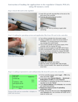
Before any handling, check that the four
transport locks fi tted are still in place and
well-tightened.
To do so, remove the front and rear casings
and check presence of four locks (B).
SAFETY
It is obligatory that all
these operations are
undertaken by handling
specialists.
Nota : in order to avoid bending of the
machine's casings, make sure to place
the lifting straps at each end of the wood-
en planks.

D0603A
D0659A
0107 2
6
Notice
Date
Page
01201138
INSTRUCTION
HANDBOOK
2/ Lifting with a fork-lift truck
This can be carried out from the front or
back, at the centre of the machine.
CAUTION
You should never handle the machine in its
longitudinal side (any other than shown on
the drawing below) with a fork-lift truck.
Important risk of parts deterioration for
those fixed under the machine.
3/ Ground moving
The machine frame is made up of two paral-
lel parts, making ground moving possible by
means of rollers.
6. Handling

D0671A
A
B
B
A
0107 3
6
Notice
Date
Page
01201138
INSTRUCTION
HANDBOOK
6. Handling
CAUTION
In order to avoid any bend-
ing of casings, you should
never climb and stand on
top of the machine.
4/ Lifting with a jack
Lifting in this case can only be done with a
jack (minimum capacity 500 daN) which can
bear the machine's weight.
Nota : in order to avoid the bending of the
sole, make sure to place the lifting jack at
each corner of the machine at point A or B.

D0660/776
0107 1
7
Notice
Date
Page
01201138
INSTRUCTION
HANDBOOK
7. Packing - Weight
Packing
Packing dimensions in mm/inch Size A Size B Size C
Washer extractor Type 250 standard 1180/46.5 1230/48.4 1840/72.4
Washer extractor Type 250 barrier 1180/46.4 1230/48.4 1840/72.4
Washer extractor Type 350 standard 1180/46.4 1450/57 1840/72.4
Washer extractor Type 350 barrier 1180/46.4 1450/57 1840/72.4
Washer extractor Type 500 standard 1180/46.4 1760/69.3 1840/72.4
Washer extractor Type 500 barrier 1180/46.4 1760/69.3 1840/72.4
Washer extractor Type 650 standard 1180/46.4 2180/85.8 1840/72.4
Washer extractor Type 650 barrier 1180/46.4 2180/85.8 1840/72.4
Weight
Weight in kg/lb (machine + crate) Gas Electric Steam/T.F
Washer extractor Type 250 standard 775/1709 775/1709 775/1709
Washer extractor Type 250 barrier 775/1709 775/1709 775/1709
Washer extractor Type 350 standard 890/1963 890/1963 890/1963
Washer extractor Type 350 barrier 890/1963 890/1963 890/1963
Washer extractor Type 500 standard 1090/2404 1090/2404 1090/2404
Washer extractor Type 500 barrier 1090/2404 1090/2404 1090/2404
Washer extractor Type 650 standard 1195/2636 1195/2636 1195/2636
Washer extractor Type 650 barrier 1195/2636 1195/2636 1195/2636
Identifi cation plate
(for gas machine only)
Adjustment label
GAS
EXCHANGER

07100081B
1009 1
8
Notice
Date
Page
01201138
INSTRUCTION
HANDBOOK
8.Technical
characteristics
Washer extractor type 250 standard
Top view
Drain connection
Front viewRight view Left view

0208 2
8
Notice
Date
Page
01201138
INSTRUCTION
HANDBOOK
Washer extractor type 250 standard Diagram no. 07100081B
8.Technical
characteristics
* normal cycle : prewash 3 min at 35 °C, drain. 2 min, main wash 4 min at 65 °C, drain 2 min, rinse 2 min, extract. 2 min, rinse 2 min, ex-
tract 2 min, rinse 2 min, extrac. 10 min (cold water supply at 15 °C).
** ECO cycle : normal cycle with rinse 5 l/kg instead of 6 l/kg dry linen.
Heating Gas Electric Steam Thermic fl uid
Characteristics Ø cage ---- ----------------------- 770 mm (30.31") -----------------
Cage length ---- ----------------------- 520 mm (20.47") -----------------
Cage volume ----------------------- 229 dm³ (229 l) ------------------
Specifi c load 1/10 ---- ------------------------- 22.9 kg (50.5 lb) ---------------
(dry linen, ISO 9398-4)
Opening cage doors (L x H) ---- ------------- 450 x 400 mm (17.71x15.74") ----------
Opening drum door (L x H) ----- ------------- 466 x 525 mm (18.34x20.67") ----------
Floor area ---- ----------------------- 1 m² (10.76 sq. ft) ---------------
Net weight ---- ----------------------- 670 daN (1478 lb) ---------------
Weight loaded (high level) ---- ----------------------- 830 daN (1830 lb) ---------------
Water volume, washing, low level 68 l 68l 68 l 68 l
Water volume, washing, high level 137 l 137 l 137 l 137 l
Max dynamic load ---- ----------------- F = 101 daN (222 lb) -----------------
Max transmitted fl oor load ---- ------------------- 814 daN (1795 lb) -------------------
Max pressure transmitted to fl oor ---- ------------------- 100 kPa -------------------------------
Spin effi ciency ---- ------------------------------ 350 G -----------------------
Max. unbalance ---- ----------------------- 3.6 kg (7.94 lb) ------------------
(L) Main switch to connect main cable
(M) Electric cable (section) 4x2.5 mm² 4x6 mm² 4x2.5 mm² 4x2.5 mm²
(N) or (N') Stuffi ng box for main cable
Supply voltage --------- ----------------380 / 415 V 3+E ~ 50/60 Hz-----------
Installed electric power 3.7 kW 21.7 kW 3.7 kW 3.7 kW
Installed heating power 40 kW 18 kW - -
Electric consumption for a normal cycle* 0.8 kWh/h 6 kWh/h 0.6 kWh/h 0.6 kWh/h
Heat loss --------- ----------3 % of installed heating power-------------
(G) Steam inlet Standard : DN 20 (3/4" BSP) Low pressure : DN 25 (1" BSP)
- Maximum supply pressure 600 kPa (87 psi)
- Steam intantaneous fl ow rate at 600 kPa 72 kg/h
- Seam consumption for a normal cycle* 12 kg/h at 600 kPa (87 psi)
(D) Hot water connection / fl ow DN 20 (3/4" BSP) - 70 l/min at 250 kPA (36 psi)
(E) Cold hard water connection / fl ow DN 20 (3/4" BSP) - 70 l/min at 250 kPA (36 psi)
(F) Cold soft water connection / fl ow (option) DN 20 (3/4" BSP) - 70 l/min at 250 kPA (36 psi)
Water supply minimum pressure --- ------------------------ 50 kPa (7.25 psi) ---------------
Water supply maximum pressure --- ------------------------ 300 kPa (43.5 psi) -------------
Water consumption for a normal cycle* 360 l 340 l 340 l 340 l
Water consumption for an ECO cycle** 282 l 260 l 260 l 260 l
(K) Liquid detergents inlet DN 20 (3/4" BSP)
(H1) Drain connection --- ------------------------ Ø 75 mm (3") --------------------
(H2) Double drain connection ---
------------------------ Ø 75 mm (3") --------------------
Maximum fl ow rate ---- -------------------------- 240 l/min -----------------------
(I) Waste water collector ---- -------------------- DN 150 mm (6" BSP) --------------
(3 cm/m (3%) minimum slope)
(J) Air vent hole ---- -------------------- Ø 60 mm (2.36 ") -------------------
(N') Thermic fl uid inlet or indirect steam heating DN 15 (1/2" BSP)
(G) Thermic fl uid return or indirect steam heating DN 15 (1/2" BSP)
- Maximum supply pressure 600 kPa
- Installed calorifi c power 34400 kcal
- Average calorifi c consumption 11500 kcal/h
- Inner volume thermic fl uid exchanger 2,62 l
Gas inlet DN 20 (3/4" BSP)
Combustion products evacuation Ø 125 mm (5")
(S) Weighing equipment (optional)
Compressed air inlet (low pressure steam) ---------------------------Ø 4/6 mm-----------------------------
- Min./max. compress air pressure -------------------5,5/7 bar--------------------------------
- Consumption --------------------------------10 l/h-----------------------------

07100083B
0408 3
8
Notice
Date
Page
01201138
INSTRUCTION
HANDBOOK
Washer extractor type 350 standard
8.Technical
characteristics
Top view
Drain connection
Front viewRight view Left view
/