Page is loading ...

Iv
Save This Manual For
Future Reference
_ARS
owners
manual
Model No.
113.248211
Single Speed Band Saw
with Leg Set
Model No.
113.248321
Two Speed Band Saw
with Leg Set
Serial
Number
Model and serial number
may be found at the
left-hand side of the base.
You should record both
model and serial number
in a safe place for future
use.
FOR YOUR
SAFETY:
Read ALL
INSTRUCTIONS
CAREFULLY.
113.248211
/
/ t _\x
/
/
/
V
113.248321 _i
SEARSICRRFTSMRN
12-1NCH BAND SAW
, assembly
° operating
° repair parts
Sold by SEARS, ROEBUCK AND CO., Chicago, IL. 60684 U.S.A.
Part No, SP5687 Printed in U.S.A.

FULL ONE YEAR WARRANTY ON CRAFTSMAN BAND SAW
If wlthln one year from the date of purchase, thls Craftsman Saw falls due to a defect in material or
workmanship, Sears wlll repalr It, free of charge.
WARRANTY SERVICE IS AVAILABLE BY SIMPLY CONTACTING THE NEAREST SEARS SERVICE
CENTER/DEPARTMENT THROUGHOUT THE UNITED STATES.
Thls warranty applies only while thls product Is used In the United States.
Thla warranty gives you specific legal rights and you may also have other rlghts whlch vary from state
to state.
SEARS, ROEBUCK AND CO., D/817 WA Hoffman Estates, IL. 60195
TABLE OF CONTENTS
Section Title Page Number
Safety Instructions for Band Saw ............................... 2
Glossary of Terms for Woodworking .......................... 6
Electrical Connections................................................ 6
General Information ................................................... 8
Model Description .................................................. 8
Unpacking and Checking Contents ............................ 8
Assembly and Alignment .......................................... 11
Assembling Leg Set ............................................. 11
AdjustingLeveling Feet ....................................... 13
Attachingthe Handwheel ..................................... 13
Mounting the Motor .............................................. 14
Connecting the Motor........................................... 17
Selecting Blade Speed ........................................ 18
Recommended Speed Settings ........................... 18
Changing Speed Settings .................................... 18
AttachingTrim Caps ............................................ 18
Gettingto Know Your Band Saw .............................. 19
Installingthe Blade .............................................. 20
Aligningthe Blade and
Blade Guide Assemblies ............... .,................ 22
Mountingthe Front Table ..................................... 24
Squaring the Blade to the Table .......................... 26
AdjustingFront Table ........................................ ,..26
Location and Function of Controls ........................... 27
On-Off Switch ....................................................... 27
Tilting Head for Bevel Cut .................................... 27
Adjusting Bevel Lock Knob .................................. 27
Basic Band Saw Operation ...................................... 28
Circle Cutting ....................................................... 31
Sawdust Collection .............................................. 31
Installing Sand ing Attach ment ............................. 32
Installing the Sanding Belt ................................... 32
Installing 1/16" Blade and
Blade Guides ................................................... 33
Scrolling............................................................... 34
Recommended Accessodes .................................... 36
Maintenance ............................................................. 36
Trouble Shooting- All Models .................................. 37
Trouble Shooting - Motor ......................................... 38
Parts Lists ................................................................ 40
Drive Assembly .................................................... 40
Base Components ............................................... 42
Bevel Drive and Motor Mount
Assembly Parts ................................................ 44
Leg Set ................................................................ 46
Safety Instructions for Band Saw
SAFETY SIGNAL WORDS
DANGER: means if the safety information is not fol-
lowed someone will be seriously injuredor killed.
WARNING: means if the safety information is not
followed someone could be seriously injured or killed.
CAUTION: means if the safety information is not fol-
lowed someone might be injured.
Safety is a combination ofcommon sense, stayingalert
and knowing how your band saw works. Read this
manual to understand this saw.
BEFORE USING THE SAW:
WARNING: To avoid mistakes that could cause i
i
serious, permanent Injury, do not plug the saw in
I
until the following steps are completed.
• Assembly and alignment. (See pages 11 - 18)
• Learn the use and function of the ON-OFF switch,
bevel handwheel, bevel lock knob, blade guides,
backup beatings, guide bar lock knob, and blade
guard (See page 19.)
• Review and understanding of all safety instructions
and operating procedures in is manual.
• Review of the maintenance methods for this saw.
(See page 36.)
Read the following WARNING labels found on the front
of the saw:
I '" I
1.Pma_e'm_ tmf_'eo_:_11w, 6.Oo r'_ mm_4 j,m_t_l eJ,eJlf p,_me_J_JI t Tw,__ _1e*_dv,_ _ b4_v b _

WHEN INSTALLING OR MOVING
THE SAW
AVOID DANGEROUS ENVIRONMENT. Usethe saw in
a dry, indoor place protected from rain. Keep work area
well lighted.
To avoid injury from unexpected saw movement:
• Put the saw on a firm level surface where there is
plenty of room for handling and properly supporting
lhe workpiece.
• Support the saw so the table is level andthe saw does
not rock,
Bolt tile saw to the floor or work surface if it tends to
slip, walk, or slide during operations like cutting long,
heavy boards.
Turn saw off and unplug cord before moving the saw.
To avoid injury or death from electrical shock:
GROUND THE SAW. This saw has an approved 3-
conductor cord and a 3-prong grounding type plug.
Use only 3-wire grounded outlets rated 120 volts, 15
amperes (amps). The green conductor in the cord is
the grounding wire. To avoid electrocution, NEVER
connect the green wire to a live terminal.
• Make sure your fingers do not touch the plug's metal
prongs when plugging or unplugging the saw.
To avoid back injury, get help or use recommended
casters when you need to move the saw. Always get
help il you need to lilt the saw.
NEVER STAND ON TOOL. Serious injury could occur
ifthe tool tips or you accidentally hit the cutting tool. Do
not store anything above or near the tool where anyone
might stand on the tool to reach them.
BEFORE EACH USE:
Inspect your saw.
DISCONNECTTHE SAW. To avoid injury from acciden-
tal starting, unplug the saw, turn the switch off and
remove the switch key before changing the setup, re-
moving covers, guards, blade or sanding belt.
CHECK DAMAGED PARTS. Check for:
• alignment of moving parts,
• binding of moving parts,
w
broken parts,
stable mounting, and
any other conditions that may affect the way the saw
works
If any part is missing, bent, or broken in any way, or any
electrical parts don't work properly, turn the saw oil and
unplug the saw. REPLACE damaged, missing, or failed
parts before using the saw again.
MAINTAIN TOOLS WITH CARE. Keep the saw clean
for best and safest performance. Follow inslructions for
lubricating.
REMOVE ADJUSTING KEYS AND WRENCHES from
tool before turning it on.
To avoid injury from jams, slips or thrown pieces or
broken blades:
• Use of right blade size, style and cutting speed forthe
material and the type of cutting you plan to do.
USE ONLY RECOMMENDEDACCESSORIES. (See
page 36.) Consult this Owner's manual for recom-
mended accessories. Follow the instructions that
come with the accessories. The use of improper
accessories may cause risk of injury to persons.
Make sure lhe blade teeth point downward, toward
the table.
Make sure the blade guides and thrust bearings are
properly adjusted.
• Make sure the blade or sanding belt tension is prop-
erly adjusted.
• Before sanding, adjust the sanding platento clearfhe
table by no more than !/8 of an inch
• Make sure the bevel clamp istight and no parts have
excessive play.
To avoid accidental blade contact, minimize blade
breakage and provide maximum blade suppo_l, al-
ways adjust fhe upper blade guide and blade guard to
just clear the workpiece.
KEEP WORK AREA CLEAN. Cluttered areas and
benches invite accidents. Floor must not be slippery.
To avoid burns or other fire damage, never use ;he saw
near flammable liquids, vapors or gases.

Plan ahead to protect your eyes, hands,
face and ears.
KNOW YOUR SAW. Read and understand the owner's
manual and labels affixed to the tool. Learn its applica-
tion and limitations as well as the specific potential
hazards peculiar to this tool.
To avoid injury from accidental contact with moving
parts, don't do layout, assembly, or set up work on the
saw while any parts are moving.
AVOIDACCIDENTALSTARTING. Make sure switch is
"OFF" before plugging saw into a power outlet.
Plan your work.
• USE THE RIGHT TOOL. Don't force tool or attach-
ment to do a job it was not designed to do.
• Use model 113.248211 to cut and sand only wood,
wood like products, and plastics.
I CAUTION: To avoid blade breakage, fire or other
damage to the saw, NEVER use model 113.248211
to cut metals.
• Use model 113.248321 to cut and sand only wood,
wood like products, plastics and non-ferrous metals.
CAUTION: Models 113.248321 is NOT designed
for cutting or sanding ferrous metals like iron or
steel. When cutting or sanding non-ferrous met-
als (brass, copper and aluminum, etc.), metal
shavings can react with wood dust and start afire.
To avoid this:
• Disconnect any type of dust collecting hose
from the saw.
• Remove all traces of wood dust from inside the
saw.
• Remove all metal shavings from inside the saw
before sawing wood again.
Dress for safety.
WEAR YOUR
Any power saw can throwforeign objects intothe eyes.
This can cause permanenl eye damage. Wear safety
goggles (not glasses) that comply with ANSI Z87.1
(shown on package). Everyday eyeglasses have only
impact resistant lenses. They are not safety glasses.
Safety goggles are available at Sears retail catalog
stores. Glasses or goggles not in compliance with ANSI
Z87.1 could seriously hurt you when they break.
o Do not wear loose clothing, gloves, neckties or jew-
elry (rings, wrist watches). They can get caught and
draw you into moving parts.
• Wearnonslip footwear.
• Tie backlong hair.
Roll long sleeves above the elbow.
Noise levels vary widely. To avoid possible hearing
damage, wear ear plugs or muffs when using saw for
hours at a time.
For dusty operations, weara dust mask along with the
safety goggles.
Inspect your workpiece.
Make sure there are no nails or foreign objects in the
part of the workpiece to be cut.
Use extra caution with large, very small or awkward
workpleces:
• Use extra supports (tables, saw horses, blocks, etc.)
for any workpieces large enough to tip when not held
down to the table lop.
NEVER use another person as a subslitule for a tab!e
extension, or as additional support for a workpiece
thai is longer or wider than the basic saw table, orto
help feed, support or pull the workpiece.
When cutting irregularly shaped workpieces, plan
your work so it will not pinch the blade. A piece of
molding, for example, must lay flat or be held by a
fixture or jig thal will not lel it twist, rock or slip while
being cut.
Properly support round material such as dowel rods,
or tubing. They have a tendency to roll during a cut,
causing the blade to "bite". To avoid this, always use
a "V" b!ock or clamp the work to the miter gage.
Cut only one workpiece at a time.

• CleareverythingexcepttheWorkpieceand related
support devices off the table before turning the saw
013.
Plan the way you will hold the workpiece from start
to finish.
Donot hand hold pieces so small that your fingers will go
under the blade guard. Use jigs or fixtures to hold the
work and keep your hands away from the blade.
SECURE WORK. Use clamps to hold work when
practical. It'soften safer than using your hand, and flees
both hands to operate the toot.
Avoid awkward operations and hand positions where a
sudden slip could cause fingers or hand to move into the
blade or sanding surface.
DON'T OVERREACH. Keep good footing and balance.
WHENEVER SAW IS RUNNING.
WARNING: Don't let familiarity (gained from fre-
quent use of your band saw) cause a careless
mistake. Acareless fraction of a second isenough
to cause a severe Injury.
Before starting your cut, watch the saw while it runs. If
it makes an unfamiliar noise or vibrates a lot, stop
immediately. Turn the saw off. Unplug the saw. Do not
restart until finding and correcting the problem.
KEEP CHILDREN AWAY. Keep all visitors a safe
distance from the saw. Make sure bystanders are clear
of the saw and workpiece.
DON'T FORCE TOOL It will do the job better and safer
at its designed rate. Feed the workpiece into the saw
blade only fast enough to let itcut without bogging down
or binding.
Before freeing anY jammed material:
• Tum switch "OFF".
• Remove switch key.
• Unplug the saw.
• Wait for all moving parts to stop.
When backing up theworkpiece, the blade may bind
in the kerf (cut). This is usually caused by sawdust
clog glng up t he kerr or because the blade comes out
of the guides, if this happens:
• Turn switch "'OFF".
Remove switch key.
Unplug saw.
Wait for all moving parts to stop.
Remove band saw cover.
Stick flat blade screwdriver or wedge into the kerl.
Turn the upper wheel by hand while backing up the
workpiece.
Before removing loose pieces from the table, turn saw
off and wait for all moving parts to stop.
BEFORE LEAVING THE SAW:
Wait for all moving parts to stop.
Makeworkshop child-proof. Lockthe shop, Disconnect
master switches. Remove the yellow switch key. Store
it away from children and others not qualified to use the
tool.

glossary of terms for woodworking
BOTH MODELS
Beveling
An angle cutting operation through the face of the
board.
Crosscut
A cutting operation made across the width of the
workpiece.
Compound Cutting
A simultaneous bevel and miter cutting operation,
FPM
Feet per minute. Used in reference to surface speed
of blade.
Freehand (as used for band saw)
Performing a cut without the workpiece properly
supported on the work table.
Gum
A sticky, sap based residue from wood products.
Kerr
The material removed by the blade in a through cut
or the slot produced by the blade in a non-through or
partial cut.
Leading End
The end of the workpiece which is pushed into the
cutting toot first.
Mitering
An angle cutting operation made across the width of
the workpiece.
Push Stick
A device used to feed the workpiece through the saw
during narrow ripping type operations so the opera-
tor's hands are kept well away from the blade.
Resaw
A cutting operation to reduce the thickness of the
workpiece to make thinner pieces.
Resin
A sticky, sap based substance that has dried.
Ripping
A cutting operation along the length of the work-
piece.
Sawblade Path
The area of the worktable or workpiece directly in
line with the saw blade,
Set
The distance the tip of the saw blade tooth is bent
outward from the face of the blade.
Trailing End
The workpiece end last cut by the saw blade.
Workpiece
The item on which the cutting operation is being
performed. The surfaces of a workpiece are commonly
referred to as faces, ends, and edges.
Worktable
The surface on which the workpiece rests while
performing a cutting or sanding operation.
electrical connections
BOTH MODELS
POWER SUPPLY
Motor Specifications
The A-C motorused inthis saw isa capacitor-start, non-
reversible type having the following specifications:
113.248321 113248211
Rated H.P ........................................ 5/8 ........... 1/2
Maximum Developed H.P .............. 1-1/8 ........... 1
Voltage ............................................ 120 .......... 120
Amperes .......................................... 7.9 ........... 7.9
Hertz (Cycles) .................................. 60 ............ 60
Phase ............................................ Single ...... Single
RPM ............................................... 1725 ........ 1725
Rotation of Shaft ........................... Clock-. .....Clock-
wise wise
WARNING: To avoid electrical hazards, fire haz-
ards, or damage to the tool, use proper circuit
protection. Your saw Is wired at the factory for
120v operetio n. Connect toa 120v, 15-amp, branch
circuit and use a 15-amp fuse or circuit breaker.
WARNING: To avoid shock or tire, If power cord
Is worn or cut, or damaged In any way, have it
replaced Immediately.
WARNING: If not properly grounded this power
tool can cause electrical Shock- particularly when
used In damp locations close to plumbing. If an
electrical shock occurs there Isalso the potential
of a secondary hazard such as your hands con-
tacting the sawblade. Not all outlets are properly
grounded. If you are not sure that your outlet is
properly grounded, have Itchecked by a qualified
electrician.
Yourunit has a plug that looks like the one shown below.

Thispowertoolisequipped with a 3-conductor cord and
ground type plug listed by Underwriters' Laboratories.
The ground conductor has a green jacket and is at-
tached to the tool housing at one end and to the ground
prong in the attachment plug at the other end.
This plug requires a mating 3-conductor grounded type
outlet as shown above.
WARNING: To maintain proper tool grounding
whenever the outlet you are planning to use for
this power tool Is of the two prong type, do not
remove or alter the grounding prong in any man-
ner. Use an adapter as shown and always connect
the grounding prong to known ground.
Have a qualified electrician replace the two prong outlet
with a properly grounded three prong outlet.
An adapter as shown is available for connecting the plug
to a 2-prong receptacles. The green grounding lead
extending from the adapter must be connected to a
permanent ground such as properly grounded outlet
box.
GROUNDING LUG
ADAPTER
PLUG _
MAKE SURE TH!S IS
-, _ - CONNECTED TO A
KNOWN GROUND
I WARNING: The adapter Illustrated Is for use only I
if you already have a properly grounded 2-prong
I
receptacle.
MOTOR SAFETY PROTECTION
NOTICE: To avoid motor damage this motor should
be blown out or vacuumed frequently to keep sew-
dust from Interfering with normal motor ventilation.
1. This tool should be connected to a 120v, 15 amp
branch circuit with a 15 amp fuse or circuit breaker.
Faiiure to use the proper size fuse cap, resui_ in
damage to the motor.
2. If the motor faUs to start, turn the power switch to the
"OFF" position immediately. UNPLUG THE TOOL.
Checkthe saw bladeto make sure itturns freely. Ifthe
blade is free, try to start the motor again. If the motor
stilldoes not start, refer to the "Motor Troubleshooting
Chart."
3. If the motor suddenly stalls while cutting wood, turn
the power switch off, unplug the tool, and free the
blade from the wood. The motor may now be re-
started and the cut finished.
4. Frequent "b!owing" of fuses or tripping of circuit
breakers may result if:
a. MOTOR IS OVERLOADED - Overloading can
occur if you teed too rapidly.
b. LOW VOLTAGE - Although the motor is designed
for operation on the voltage and frequency speci-
fied on the motor nameplate, normal loads will be
handled safely on voltages not more than 10%
above or below the nameplate voltage. Heavy
loads, however, require voltage at motor terminals
equals the voltage specified on nameplate.
5. Most motor troubles may be traced to loose or incor-
rect connections, overload, reduced input voltage
(such as small size wire in the supply circuit) or to
overly long supply circuit wire. AM,ays check the
connections, the load and the supply circuit whenever
motor fails to perform satisfactorily. Check wire size
and length with the Wire Size Chart below.
WIRE SIZES
The use of any extension cord will cause some loss of
power. To keep this to a minimum and to prevent
overheating and motor burn-out, use the table below to
determine the minimum wire size (A.W.G.) extension
cord. Use only 3-wire extension cords which have 3-
prong grounding type plugs and 3-pole receptacles
which accepts the tools plug.
CAUTION: For circuits that are farther away from
electrical service box, the wire size must be In-
creased proportionately In order to deliver ample
voltage to the saw motor.
Length of the 120 Volts Wire Sizes Required
Conductor (American Wire Gage Number)
0 - 25 Ft. 16
26 - 50 Ft. 14
51 - 100 Ft. 12
7

general information
BOTH MODELS
1. This manual is1orthe following Models - 113.248211
and 113,248321. All sections are labeled with the
correct model number. Follow ONLY instructions
that are meant for your model saw.
2. If you are missing anypart(s) while putting your saw
together, do not continue assembly. Contact your
Sears Service Center or Retail Store and get the
missing part(s) before continuing assembly or trying
to use the saw.
Complete parts lists are located at the end of this
manual. Use these liststo identifythe number of any
missing part.
3. Sometimes small parts get lost in packaging materi-
als. Do not throw away any packaging until your saw
is put logether. If you are missing a part, check
packaging before contacting Sears.
MODEL DESCRIPTION
MOdel 113.248211: Manual Band Saw; 18 x 23 inch
Work table; single speed; 1/2 HP. motor that develops
1 H.P.; legset.
Model 113. 248321: Manual Band Saw; 27 x 23 inch
work table; two speed; 5/8 HP. motor that develops
1-1/8 H.P.; legset.
unpacking and checking contents
BOTH MODELS
TOOLS NEEDED
MEDIUM SCREWDRIVER
_' _....... 3/8" WRENCH
7/16" WRENCH
COMBINATI 9/16" WRENCH
SQUARE_
7/16" SOCKET
9/16" SOCKET
1/8" HEX "L" WRENCH R_
5/32" HEX "L" WRENCH _ SOCKET WRENCH
COMBINATION SQUARE MUST BE TRUE
f
STRAIGHT EDGE OF
BOARD 3/4-INCH THICK
THIS EDGE MUST BE
PE_CTLY STRAIGHT
DRAW LIGHT
LINE ON BOARD
ALONGTHIS EDGE _,,_ J
SHOULD BE NO GAP OR OVERLAP HERE WHEN
SQUARE IS FLIPPED OVER IN DOTTED POSITION
WARNING: To avoid Injury from unexpected
starting or elect rical shock, do not plug the saw in
until all assembly and alignment steps are com-
plete. The power cord must remain unplugged
whenever you are working on the saw.
Unpacking and Checking Contents
1. Separate all "loose parts" from packaging materials
and check each itemwith "Table of Loose Parts" to
make sure all items are accounted for, before discard-
ing any packing material.
l WARNING: If any parts are missing, do not at-
tempt to assemble the band saw, plug in the
power cord, or turn theswitch on until the missing
parts are obtained and are installed correctly.
2. Remove front table and front cover first while saw is
being unpacked. To remove the front cover, pull the
cover at the neck and underside of throat area.

TABLE OFLOOSEPARTS
ITEM DESCRIPTION QTY.
A Motor ............................................................. 1
B Basic Saw Assembly ................................... 1
C Owners Manual ...........
.................................. 1
D Trim Cap, LH ............................................... 1
E Trim Cap, R.H .............................................. 1
F Leg ................................................................ 4
G Lower Stiffener ............................................ 4
H Sanding Platen ............................................. 1
I Poly "V" Drive Belt ...................................... 1
J Pulley ........................................................... 1
K Loose Parts Bag
containing tile following items:
Band Saw Blade 1/4 x 80 ........................ 1
Sanding Be!l 1/2 x 80 ............................. 1
Handw,heel Assembly ............................ I
Bag of Loose Parts ............................... 3
L Leg Chanr}e', ............................................. 1
NOTE: To avoid damage to the band saw leave it
laying on its left side until you are ready to mount it
to the leg set or cabinet To prevent scratching the
finish, lay a p_ece of the packing box under the saw.
A
D
F
J
E
K

BOTH MODELS
LIST OF LOOSE PARTS IN BAG
ITEM DESCRIPTION QTY.
A Truss Head Screw 1/4-20 x 12 ..................... 32
B Lockwasher, External 1/4 ............................. 32
C Hex Nut 1/4 -20 ............................................ 32
D Leveling Foot .................................................. 4
E HexJam Nut3/8-16 ....................................... 8
F Bracket Leg .................................................... 4
A
Dllr
LIST OF LOOSE PARTS IN BAG
ITEM DESCRIPTION QTY.
G Pan Hd. Screw 10-32 x 2 ............................... 1
H Hex Nut 10-32 ................................................ 1
I Switch Key ..................................................... 1
J Lo Hd. Screw Cap 1/4-20 x 5/8 ...................... 2
K Spacer#10 x 1/4 ............................................ 4
L Hex Flange Lock Nut 10-32 ........................... 4
M Locking Setscrew 1/4-20 x 1/2 ....................... 3
N Wing Nut 5/16-18 ........................................... 1
O Washer7/32 x 1 x 1-1/16 ............................... 1
O Washer 13/64 x 5/8 x 1/32 ............................. 2
P Pan Hd. Screw Type TT 10-32 x 3/8 .............. 2
Q Hex Hd. Screw Ty TT 1/4-20 x 5/8 ................. 4
([]_\\t;\\\\\\;\\\\\\\\\\\\\\\\\\\\\\\\\\\\\\\\\\\\_e
LIST OF LOOSE PARTS IN BAG
ITEM DESCRIPTION QTY.
R Table Alignment Key ...................................... 1
S Table Latch .................................................... 2
T Belt Tension Stud ........................................... 1
U Table Latch Spring ......................................... 2
V Table Alignment Spring .................................. 2
W Key3/16Sq. x 15/16 ...................................... 1
R _
]-
*NOT SHOWN TO SCALE
I0

assembly and alignment
BOTH MODELS
ATTACHING LEVELING FEET
From the loose parts bag find the following hardware:
ITEM DESCRIPTION QTY.
A Support Bracket ............................................. 4
B Leveling Feet .................................................. 4
C Hex Nut 3/8-16 ............................................... 8
From the loose parts find the following items:
D Leg ................................................................. 4
*U
*D
*NOT SHOWN TO SCALE
1. Mount floor leveler support brackets inside legs.
Line up the three tabs on brackels with slots on leg
and tap into place. Make sure lip on bracket points
up. Install the remaining three brackets the same
way.
¢
-- LEG
®
="l"
SUPPORTBRACKET
2 Put a hex nut on each ofthe !eveling feet and screw it
down towards the rubber foot.
3, Put the leveling feet through the holes in the bottom
of the tloor leveler support bracket.
4, Put another hex nut on each of the leveling feet and
hand tighten until they are next to the support bracket.
I WARNING: After the legset has been attached to
the basic saw assembly, it will be necessary to
adjust the leveling feet so the saw does not rock.
EX NUTS
I
SUPPORT BRACKET _
LEVELING FOOT
11

BOTH MODELS
ATTACHING LEG SET
From the looseparts bag find the following hardware:
Item Description Qty.
A Truss Head Bolts 1/4-20x 1/2........... 32
B Lockwashers External 1/4............. 32
C Hex Nuts 1/4-20...................... 32
From the looseparts find the following items:
D Leg Channel ........ . .............. 1
E Legs (with attached support brackets and
levelingfeet) 4
F Lower Stiffeners .................... 4
B ¢
E* F_
*NOT SHOWN TO SCALE
,
1. Lay a piece of cardboard on the floor to keep from
scratching the saw.
2. Position the basic saw assembly on the floor as
shown below. The back cabinet of the saw should be
laying flat on the floor. It may be necessary to have
someone help you lift the saw.
SWITCH
FRONT
3, Mount the two front legs to the basic saw assembly
using truss head bolts, Iockwashers, and nuts.
Make sure that the four (4) holes in each corner of
the saw line up with the four (4) holes in the top of
each leg, Atthis time only put bolts through the sides
of the saw assemblynotthe front. Only fingertighten
nuts.
4,
Position the leg channel inside the legset as shown.
Fasten the channel piece, leg, and saw together
with two (2) truss headbolts on each side. The
threaded section of the bolts should point towards
the inside of the basic saw assembly Put a lock-
washer and hex nuton each bolt. Fingertighten nuts
at this time.
NUT 7_-_/
LOCKWASHER
FRONTLEGSAND
CHANNEL ARE
A3q-ACHED HERE
LEG
REAR LEGSARE
3HEDHERE
FLOOR
;CHANNEL
LEG
_ TRUSSt_,---HEAD
SCREW
Truss head screw, lockwasher, hex nut, and front channel p_ece
12

5. Use truss head bolts, Iockwashers, and hex nuts to
mount the two (2) rear legs to the basic saw assem-
bly. It may be necessary to slightly tilt the saw as-
sembly backwards inorder to get the four (4) holes in
each corner of the saw to line up with the four (4)
holes in the top of each leg. Finger tighten nuts at
this time.
6. Attach the four (4)lower stiffeners to the legs. Two (2)
truss head bolts, washers, and hex nuts are re-
quired to hold each end of a lower stiffener in place.
Only hand tighten hex nuts.
TRUSS HEAD BOLT-'-"--"
WASHER
LEG
i , HEX NUT
7. Go back with a 7_6wrench or socket and tighten all
hex nuts.
8. Carefully lift the saw into its normal position. It may
be necessary to have someone help you in order to
avoid damaging the saw.
STIFFENER
ADJUSTING LEVELING FEET
I WARNING: TOavoid injury from unexpected saw I
or work movement, leveling feet must be adjusted
so that saw does not rock.
To adjust leveling feet so the saw will sit properly:
1, Move saw to desired location.
2. Raise or lower leveling foot by turning it clockwise or
counterclockwise.
3. Tighten nuts to lock leveling foot in place.
ATTACHING THE HANDWHEEL
1. From loose parts bag find one (1) pan head screw
10-32 x 2and one (1) hex nut. Install the hand-
wheel. Reach inside the base to the back side of
the bevel mechanism and put the nut in place.
Hold the nut in place with a finger. Install the
screw through the center of the handwheel and
tighten with a phillips screwdriver.
2. Hotd the handle and pu!t the red release button
witil your finger to close the handle.
C,,Cf_,,
, ,'!.
i
13

BOTH MODELS
MOUNTING THE MOTOR
1. Findthe following parts:
ITEM DESCRIPTION QTY.
A Motor .............................................................. 1
B Spacer (#10 x 1/4) .......................................... 3
C Flanged Locknut #10-32 ................................ 4
D Wing Nut 5/16-18 ........................................... 1
E Motor Pulleyw/Set Screw
(Model 113.248321) ................................... 1
F Belt Tension Stud ........................................... 1
G Motor Pulleyw/Set Screw
(Model 113. 248211) .................................. 1
H Poly "V" Belt ................................................... 1
I Key 3/16 Sq x 15/16 ...................................... 1
*NOT SHOWN TO SCALE
2. Place the three (3) spacers onto the three motor
studs asshown. Pay attention towhere the oil plug is
located, No spacer goes on the fourth motor stud.
MODEL 113.248211 ONLY
3. Locate the correct motor pulley (has no step). Place
theshaft key intothe groove onthe motorshaft. Align
the groove inthe pulley with the shaft key and install
the motor pulley onto the motor shaft with the set
screw boss towardthe motor. Positionthe outerlace
ofthe pulley 2 inches fromthe end shieldofthe motor
and tighten the set screw using a 1/8-inch hex "L"
wrench.
PULLEY
OIL PLUG
MODEL 113.248321 ONLY
4. Locate the correct motor pulley (Model 113.248211
has "one-step" pulley). Place the shaft key into the
groove on the motor shaft. Align the groove in the
pulley wit h the shaft key and install the motor pulley on
the motor shaft with the setscrew boss toward the
motor,
e
14

BOTH MODELS
5. Place the Poly "V" belt into the motor mount as
shown on the underside of the band saw.
6. Look at the motor mou nt and find the slot that is nar-
rower than the other three. When mounting the
motor, the motor stud without a spacer goes into this
slot.
MOTOR MOUNT
NARROW
SLOT
7. Carefully position the motor sothat the poly "V" belt
is around the motor pulley and the four motor studs
align with the slots in the motor mount.
8. Push motor studs through and install the flanged
lock nuts to the three (3) motor studs with spacers.
Start the flanged nuts by hand only at this time.
MOTOR MOUNT
9, Install the threaded stud through the hole in the
lower legof the motor mount and over the motor stud
as shown.
THREADED STUD
MOTORMOUNT
/
15
, ,, ......... ,,,==,,

|OTH MODELS
). Install a flanged lock nut onto this motor stud.
Tighten the flanged lock nuts, using a 3/8-inch
wrench, until almost tight. It will be easier to tighten
lock nuts if the head is tilted to approximately 45 °.
See page 34 for instructions on tilting head.
OTE: Do not over-tighten the flange nuts. The motor
_ould slide in the grooves to allow tensioning of the
elt.
FLANGEDI _'-
1. Install the wing nut on the threaded stud.
2. Check that the poly "V" belt is on both pulleys being
sure that it is centered on each pulley.
3. Check that the pulleys are in line by sighting down
the sideof the large pulley to see if it lines up with the
small pulley. If the pulleys are not in line, loosen the
set screw holding the pulleyon the motor shaft and
position the pulley. A notch in the small end of the
motor support isprovided for access tothe set screw
and belt.
l'
ACCESS \
NOTCH
ILLEY
SMALL PULLEY
/
FLANGEO LOCK NUI WING NU!
I"
4. Belt tensioning isdone by lightening the wing nut
which pulls the motor down. The motorslides onthe
three (3) spacers and is locked in place by the
flanged lock nuts on the threaded studs•
Belt tension is important. Over tensioning may
cause vibration while too little tension may allow the
belt to slip under heavy loads.
5. After belt tension is adjusted correctly, tighten all
four flanged Iocknuts.
NOTE: When itbecomes necessary to readjust belt
tension, be sure to slightly loosen the flour flanged
lock nuts.
TIGHTEN FLANGE
NUT AFTER TENSIONING
BELTWITH WING NU'I
e

BOTH MODELS
0
CONNECTING THE MOTOR
1. Next, the motorcord needs to be wired intothe motor
Coming from the underside of the table will be acord
with a black, white and green wire This is the motor
cord.
WARNING: Foryourown safety, neverplug the 1
saw in until all assembly steps are completed.
]
2. Loosen the two screws holding the connector box
cover on theback side ot the motor. Swing the cover
open.
3. Install the green ground wire by removing the green
grounding screw and inserting it through the round
metal terminal on the green ground wire of the motor
cord. Reinstall the green screw into the hole from
which it was removed and tighten securely.
41
.
6.
.
WARNING: To avoid electrocution, never con-
nect but the ground wire (colored green) to the
green screw.
Insert terminal end of WHITE wire on spade terminal
marked T4 on the motor. Push terminal firmly until
seated.
Insert terminal end of BLACK wire on spade terminal
marked T1 on the motor. Push terminal firmly until
seated.
Close motor connector box being sure that power
cord is seated in the largest strain relief groove and
tighten box cover screws.
DO NOT plug in power cord.
Q
17

MODEL 113.248321 ONLY
SELECTING BLADE SPEED
The band saw has two speed settings: 3000 FPM for
normaloperation and 1500 FPM for operation requir-
ing more control of the work piece.
i
RECOMMENDED SPEED SETTINGS
1. 3000 Feet per Minute
a. Basic Wood Cutting.
b. Resawing
Most effectivewith skip tooth, hook tooth,and regular
tooth blades.
2. 1500 Feet per Minute
a. Intricate Wood Cutting
b. Veneers, Tile, Plastics
c. Non-Ferrous Metals (Brass, Copper, Aluminum.)
Most ellective with blades that have 15teeth per inch.
_-]
1500 3000
RPM RPM
MOTOR
J
CAUTION: Model 113.248321 isNOT designed for
cutting or sanding ferrous metals like iron or
steel. When cutting or sanding non-ferrous met-
als (brass, copper and aluminum, etc.), metal
shavings can react with wood dust and start a fire.
To avoid this:
- Disconnect any type of dust collecting hose
from the saw.
• Remove all traces of wood dust from inside the
saw.
• Remove all metal shavings from inside the saw
before sawing wood, again.
CHANGING SPEED SETTING
WARNING: To avoid injury from unexpected
starting or electric shock, do not plug the saw in.
The power cord must remain unplugged when-
ever working on the saw.
1. Slightly loosen the four (4) flanged lock nuts that are
holding the motor to the motor mount.
2. Release tension on the poly "V" belt.
3. Push the motor up to create slack in the "V" belt.
4. While still holding the motor up, repositioh the "V"belt.
I
.
6.
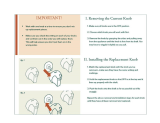
When changing speeds from 1500 to 3000 FPM,
remove the beIt from the band saw pu Iley first. When
going from 3000 to 1500 FPM, remove the belt from
the motor pulley first.
Re-apply tension to motor belt ty tightening the wing
nut.
After belt tension isadjusted correctly, tighten all four
(4) flanged lock nuts.
I
BOTH MODELS
ATTACHING TRIM CAPS
1. Find the leftand right trim caps.
2. There are two plastic stubs on the back of each trim
cap.
3. These stubs will snap into matching holes at the
front corner of each saw.
4. Snap the left & right trim caps in place.
TRIM CAP
€
18

getting to know your band saw
O
2
1 z_.s,o.ADJUST.E.TK.OB
WA,N,,_.AB_. 4 * 5 6
BEARING
BLADE GUIDES
BLADE GUIDES
6
BACK-UP BEARING
BEVEL SCALE
3
BEVEL LOCK KNOB
MITER GAGE SLOT
O
HAI,IDWHEE L
BOTH MODELS
ON-OFF SWITCH
O
1. Warning Label
2. Tensions Adjustment Knob - Tightening the knob
will increase the tension on the blade. Loosening it
wili decrease the tension. Clockwise to tension,
counterclockwise to loosen.
3. Setting Bevel Angle - Pull the bevel lock knob and
adjust he band saw to the desired angle byturning the
handwheel, then push in the bevel lock to secure.
4. Blade Guide Adjustment - The guides can be ad-
justed in or out for various widths of blades and locked
in place by the set screws.
5. Lateral Blade Guide Adjustment - The guides can
be adjusted sideways and locked in position by the
capscrews to prevent the blade from twisting during
operation.
6. Blade Backup Bearing Adjustment - The thrust
bearings can be adjusted in or out for various widths
of blades and locked in place by the setscrews.
7, Guide Bar Lock Knob - The upper blade guides
should just clear the werkpiece while cutting, Always
adjust theguides before turning on the band saw and
lock the guide bar by tightening the knob.
7
GUIDE BAR _'_
LOCKK.OB--_.!_!___, rr'
19

BOTH MODELS
INSTALLING "I'HE BLADE
WARNING: To avoid Injury from accidental start-
Ing, make sure the power cord is unplugged
before removing any part from the saw.
1. Remove the blade guard by loosening the two (2)
mounting screwswith aphillipsscrewdriverand lifting
the blade guard upward,
Ill\
4
_\_ !1 r "_BLADE GUARD
_\'I_FII MOUNT=NG
i' SCREW
GUARD
2. Loosen the upper blade guide assembly and
lower to approximately 3 inches above rear table
and retighten lock knob. This is necessary to
make adjustments to blade guide and back up
roller bearing.
3. Loosen the two capscrews that lock the upper
blade guides using a 1/8-inch hex "L" wrench
and separate them about 1/8-inch. Repeat the
same step for the lower blade guides.
BLADE GUIDE
CAPSCREWS
0
2O
/