Mitsubishi WD-65733 Owner's manual

Category
LCD TVs
Type
Owner's manual
DLP® HIGH-DEFINITION
MODELS
C Series
WD=C657
Y Series
WD=Y577,WD=Y657
733 Series
WD=57733, WD=65733, WD=73733
734 Series
WD=57734, WD=65734, WD-73734
OWNER'S GUIDE
TELEVISION
For questions:
Visit our website at www.mitsubishi-tv.com.
E-mail us at [email protected].
Call Consumer Relations at 800-332-2119.
For information on System Reset, please see the back cover.
To order replacement or additional remote controls, lamp cartridges, or Owner's Guides,
visit our website at www.mitsuparts.com or call 800-553-7278.
Guidelines for setting up and using your new widescreen TV start on page 11.
x.v.Color HiGH DEFiNITiON MULTiM EDiA iNTERFACE
_Lp®PICTUREBY
TEXASINSTRUMENTS
For Your Records
Record the model number, serial number, and
purchase date of yourTV. The model and serial
numbers are on the back of the TV. Refer to this
page when requesting assistance with the TV.
MODEL NUMBER __
SERIAL NUMBER
PURCHASE DATE
RETAILER NAME
LOCATION
CAUTION: TO REDUCE THE RISK OF ELECTRIC
SHOCK, DO NOT REMOVE COVER (OR BACK).
NO USER SERVICEABLE PARTS INSIDE.
REFER SERVICING TO QUALIFIED SERVICE
PERSONNEL.
The lightning flash with arrowhead
symbol within an equilateral triangle is
intended to alert the user of the pres-
ence of uninsulated "dangerous voltage"
within the product's enclosure that may
be of sufficient magnitude to constitute
a risk of electric shock to persons.
The exclamation point within an equilat-
eral triangle is intended to alert the user to
the presence of important operating and
maintenance (servicing) instructions in the
literature accompanying the product.
WARNING: TO REDUCE THE RISK OF FIRE
OR ELECTRIC SHOCK, DO NOT EXPOSE THiS
APPLIANCE TO RAiN OR MOISTURE.
TV WEIGHT: This TV is heavy! Exercise extreme care
when lifting or moving it. Lift or move the TV with a
minimum of two adults. To prevent damage to the TV,
avoid jarring or moving it while it is turned on. Always
power off your TV, unplug the power cord, and discon-
nect all cables before moving it.
WARNING: This product contains chemicals known
to the State of California to cause cancer and/or birth
defects or other reproductive harm.
FCC Declaration of Conformity
Product:
Models:
Responsible
Party:
Telephone:
Projection Television Receiver
WD-C657
WD-57733, WD-65733, WD-73733
WD-Y577, WD-Y657
WD-57734, WD-65734, WD-73734
Mitsubishi Digital Electronics
America, Inc.
9351 Jeronimo Road
Irvine, CA 92618-1904
(800) 332-2119
This device complies with Part 15 of the FCC Rules.
Operation is subject to the following two conditions:
(1) This device may not cause harmful interference,
and
(2) this device must accept any interference
received, including interference that may cause
undesired operation.
Note: This equipment has been tested and found
to comply with the limits for a Class B digital device,
pursuant to part 15of the FCC Rules. These limits
are designed to provide reasonable protection
against harmful interference in a residential instal-
lation. This equipment generates, uses and can
radiate radio frequency energy and, if not installed
and used in accordance with the instructions, may
cause harmful interference to radio communica-
tions. However, there is no guarantee that interfer-
ence will not occur in a particular installation. If this
equipment does cause harmful interference to radio
or television reception, which can be determined
by turning the equipment off and on, the user is
encouraged to try to correct the interference by one
or more of the following measures:
Reorient or relocate the receiving antenna.
Increase the separation between the equip-
ment and the receiver.
Connect the equipment into an outlet on
a circuit different from that to which the
receiver is connected.
Consult the dealer or an experienced
radio/TV technician for help.
Changes or modifications not expressly
approved by Mitsubishi could cause harmful
interference and would void the user's authority
to operate this equipment.
Contents
Important Information About Your TV
General Warnings and Cautions, Notes on
Installation and Operation ................. 4
Important Safeguards ..................... 5
1 Television Overview
Package Contents ....................... 6
Special Features of Your TV ................ 6
TV Front Panel .......................... 7
TV Back Panel .......................... 9
2 TV Setup
Guidelines for Setting Up and Using Your New
Widescreen TV........................ 11
Installing the Remote Control Batteries ........ 12
When You First Power On the TV ............ 12
Initial TV Setup ......................... 12
Setting Up TV Inputs .................... 13
Controlling A/V Receiver Sound Volume ....... 14
Using the TV with a Personal Computer ....... 15
3 TV Connections
Before you Begin ....................... 17
HDTV Cable Box or Satellite Receiver with
Component Video ..................... 17
Standard Cable Box, Satellite Receiver, or Other
Device with S-Video .................... 18
HDMI Device (Cable Box, Satellite Receiver,
DVD Player, or Other Device) ............... 18
Wall Outlet Cable (no cable box) ............ 19
Antenna with a Single Lead ................ 19
Antennas with Separate UHF and VHF Leads... 19
DVD Player with Component Video .......... 20
DVI Video Device (Cable Box, Satellite Receiver,
DVD Player, or Other Device) .............. 20
VCR to an Antenna or Wall Outlet Cable ....... 21
VCR to a Cable Box (Audio & Video) .......... 22
A/V Receiver (Sound System) .............. 23
Older Cable Box ........................ 23
Camcorder ........................... 24
4 TV Operation and Features
Choosing a Viewing Source ................ 25
Sleep Timer ........................... 25
Remote Control ........................ 26
ChanneIView TM Channel Listings ............ 27
Status Display ......................... 28
FAV (Favorite Channels) ................... 29
TV Signals and Display Formats ............ 30
Viewing Camera Files .................... 32
JPEG Photos and the USB Photo Port ..... 32
Photos and Moving Video as Composite
Video ............................ 33
5 TV Menu Settings
Remote Control Keys for the TV Menu System . . 34
Main Menu ............................ 34
AV Menu ............................. 35
Video Menu ........................ 36
Audio Menu ........................ 37
Captions Menu ......................... 38
Setup Menu ........................... 39
Inputs Menu ........................... 43
Lock Menu ............................ 44
Setting or Resetting a Pass Code ......... 44
Parent Menu ....................... 44
Other Menu (Alternate Rating System) ..... 44
Bypassing TV Locks .................. 44
6 NetCommand
About NetCommand ..................... 47
IR Emitter Placement (NetCommand®) ........ 48
Initial NetCommand Setup for Most Devices .... 49
Add or Remove Device Keys from NetCommand
Control ............................. 49
NetCommand Specialized Device Keys ....... 50
Operating NetCommand-Controlled Devices . . . 51
Set Up NetCommand Control of an A/V Receiver 53
Appendices
Appendix A: Specifications ................ 58
Appendix B: Bypassing the Parental Lock ..... 59
Appendix C: Lamp-Cartridge Replacement and
Cleaning ............................ 61
Appendix D: Programming the Remote Control . 63
Appendix E: Troubleshooting .............. 71
Trademark and License Information .......... 77
Mitsubishi TV Software .................... 78
Mitsubishi DLP TM Projection Television Limited
Warranty ............................. 79
Index ................................. 81
important information About Your TV
Installation Notes
Stand Requirement
CAUTION: Use these Mitsubishi TV models only with
the Mitsubishi stand models shown here. Other stands
can result in instability and possibly cause injury.
WD-57733
WD-Y577 MB-57PB
WD-57734
WD-65733
WD-Y657 MB-65PB
WD-65734
WD-C657 MB-65G
WD-73733
MB-73PB
WD-73734
Custom cabinet installation must allow for proper
air circulation around the television.
NOTE TO CATV SYSTEM iNSTALLER: THIS
REMINDER IS PROVIDED TO CALL THE CATV SYSTEM
INSTALLER'S ATTENTION TO ARTICLE 820-40 OF THE
NEC THAT PROVIDES GUIDELINES FOR THE PROPER
GROUNDING AND, IN PARTICULAR, SPECIFIES THAT
THE CABLE GROUND SHALL BE CONNECTED TO
THE GROUNDING SYSTEM OFTHE BUILDING, AS
CLOSE TO THE POINT OF CABLE ENTRY AS PRACTI-
CAL.
Operating Notes
Internal Fans
Internal cooling fans maintain proper operating tempera-
tures inside the TV. It is normal to hear the fans when you
first turn on the TV, during quiet scenes while viewing the
TV, and for a short time after turning off the TV.
Lamp Replacement
For lamp-replacement instructions, see Appendix C.
To Order a Replacement Lamp Under Warranty
Call (800) 553-7278. Please have model number, serial
number, and TV purchase date available.
important: All lamps replaced under warranty must be
returned to Mitsubishi where they will be inspected for
defect verification.
Cleaning Recommendations
Normally, light dusting with a dry, non-scratching
duster will keep your TV clean. If cleaning beyond this
is needed, please use the following guidelines:
First, turn off the TV and unplug the power cord from
the power outlet.
ToP and Sides of the TV
Occasionally clean dust build-up from the air-intake
grilles on the back and sides of the TV. Clean using
a vacuum cleaner with a brush attachment.
Gently wipe down your TV with a soft, non-abrasive
cloth such as cotton flannel or a clean cloth diaper,
lightly moistened with water. Dry with a second dry,
soft, non-abrasive cloth.
For oily dirt, add a few drops of mild liquid deter-
gent, such as dishwashing detergent, to the water
used to moisten the cloth. Rinse with a second
cloth moistened only with water. Dry with a third
dry, soft, non-abrasive cloth.
Screen
Follow the instructions for the top and sides, wiping
gently in an up and down motion.
Clean the entire screen evenly, not just sections of
the screen.
Do not allow liquid to drip down the screen, as
some liquid may enter the TV through the gap
between the screen and screen frame.
You may purchase Mitsubishi Screen Cleaner, part
number CLEANER-VSS, by calling (800) 553-7278.
DO NOT allow liquid to enter the TV through the
ventilation slots or any crevice.
DO NOT use any strong or abrasive cleaners, as
these can scratch the surfaces.
DO NOT use any cleaners containing ammonia,
bleach, alcohol, benzene, or thinners, as these can
dull the surfaces.
DO NOT spray liquids or cleaners directly on the
TV's surfaces.
DO NOT scrub or rub the TV harshly. Wipe it gently.
To Purchase a Replacement Lamp After Warranty
Visit our website at www.mitsuparts.com or call
(800) 553-7278. Order new lamp part number
915P061010.
TV Software
Do not attempt to update the software of this TV with
software or USB drives not provided by or authorized
by Mitsubishi Digital Electronics America, Inc. Non-
authorized software may damage the TV and will not be
covered by the warranty.
important Safeguards
Please read the following safeguards for your TV and retain for future reference. Always follow all warnings and instructions
marked on the television.
1. Read, Retain and Follow All Instructions. Read all safety and operating instructions before operatingthe TV. Retainthe safety and operating
instructions for future reference. Follow alloperating and use instructions.
2. Heed Warnings. Adhere to allwarnings on the appliance and in theoperating instructions.
3. Cleaning. Unplug the TV from the wall outlet before cleaning. Do not use liquid, abrasiveor aerosol cleaners. Cleanerscan permanently
damage the cabinet andscreen. Usea lightly dampened cloth for cleaning.
4. Attachments and Equipment. Neveradd anyattachments and/or equipment without approval of the manufacturer as such additions may
result in the risk offire, electric shock or other personal injury.
5. Water and Moisture. Do not usethe TVwhere contact with or immersion inwater ispossible. Do not use nearbath tubs, wash bowls, kitchen
sinks, laundry tubs, in awet basement, swimming pools,etc.
6. Accessories. Do not place the TV on an unstablecart, stand, tripod, or table. TheTVmay fall, causingserious injuryto a
child, adult or pet and serious damage to the TV. Useonly with acart, stand, tripod, bracket or table recommended bythe
@
manufacturer,or sold with the TV. Any mounting of the TVshould follow the manufacturer's instructions, andshould use
mounting accessories recommended by the manufacturer.
An appliance and cart combination should be moved with care. Quick stops, excessiveforce, and unevensurfaces may cause
the applianceand cart combination to overturn.
7. Ventilation. Slots and openings in the cabinet areprovided for ventilation and to ensure reliableoperation of the TVand to protect it from
overheating. Do not block these openings or allow them to be obstructed by placing the TV on abed, sofa, rug, or other similar surface. Nor
should it be placed overa radiator or heatregister. Ifthe TVisto be placed in a rack or bookcase,ensurethat there isadequate ventilation and
that the manufacturer's instructions havebeen adhered to.
8. Power Source. ThisTV should be operated only from the type of power source indicated on the marking label. Ifyou arenot sure of the type of
power supplied to your home, consult your appliance dealeror local power company.
9. Grounding or Polarization. This TV is equipped with a polarized alternating current lineplug havingoneblade wider thanthe other. This plug
will fit into the power outlet only one way. This isa safety feature. Ifyou are unable to insert the plugfully into the outlet, try reversingthe plug.
Ifthe plug should still fail to fit, contact your electrician to replaceyourobsolete outlet. Do not defeat the safety purpose of the polarized plug.
10. Power-Cord Protection. Power-supply cords should be routed so that they are not likelyto be walked on or pinched by items placed upon or
against them, payingparticular attention to cords at plugs, conveniencereceptacles, and the point where they exit from the TV.
ff. Lightning. Foradded protection for this TVduring a lightning storm, or when it is left unattended and unused for long period of time, unplug it
from the wall outlet and disconnect the antenna orcable system. This will prevent damage to the TV dueto lightning and power-linesurges.
12. Power Lines. An outside antenna systemshould not be located in the vicinity of overhead power lines or other electric light or power circuits,
or where it can fall intosuch power linesor circuits. When installing an outside antenna system,extreme careshould be taken to keep from
touching such power linesor circuits as contact withthem might be fatal.
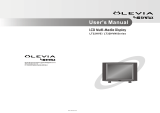
13. Overloading. Do not overloadwall outlets and extensioncords asthis can result in arisk offire or EXAMPLEOFANTENNAGROUNDING
electric shock. __._.._
14. Object and Liquid Entry. Neverpush objects of any kind into this TV through openings as they _EAO_,W,RE
may touch dangerousvoltage points or short-out parts thatcould resultinfire or electric shock. GROO,D_AMp A"TE""A
Neverspill liquid of any kind onor into the TV. _,'sE_"_"_'__o_
15. Outdoor Antenna Grounding. Ifan outside antennaor cable system isconnected to the TV,be _ROO"D'N_.
surethe antennaor cable system is grounded so as to providesome protection against voltage _N°_°_ ..... )
surges and built-up static charges. OONO_A_
Article 810of the National Electric Code,ANSI/NFPA No.70-2002, provides informationwith _-PowER _ER_E_ROO,O_,,
ELECTRODE SYSTEM
respect to proper grounding of the mastand supporting structure, grounding of the lead inwire to NECNAT,ONALELECTRICALCODE(NECART250,PARTH)
an antenna discharge unit, sizeof grounding conductors, location of antennadischarge unit, con-
nection to grounding electrodes, and requirements for the grounding electrode.
16. Servicing. Do not attempt to service this TV yourself asopening or removing covers may exposeyou to dangerous voltage or other hazards.
Referall servicing to qualified service personnel.
17. Damage Requiring Service. Unplug the TVfrom the wall outlet and refer servicing to qualified service personnel underthe following
conditions:
(a) Whenthe power-supply cord or plug is damaged.
(b) If liquid has beenspilled, or objects havefallen into the TV.
(c) Ifthe TV hasbeen exposed to rain or water.
(d) If the TV does not operate normally byfollowing the operating instructions, adjust onlythose controls that are covered by the operating
instructions asan improper adjustment of other controls may result in damage andwill often require extensivework by aqualified techni-
cian to restore the TV to its normaloperation.
(e) If the TV hasbeen dropped or the cabinet has been damaged.
(f) Whenthe TV exhibits a distinct change in performance - this indicatesa needfor service.
18. Replacement Parts. When replacement parts are required, be surethe service technician has used replacement parts specified bythe
manufacturer or havethe samecharacteristics asthe original part. Unauthorizedsubstitutions may result in fire, electric shock or other hazards.
19. Safety Check. Upon completion of anyservice or repairto the TV,askthe servicetechnician to perform safety checks to determinethat the TV
is in safe operating condition.
20. Heat. The product should be situated awayfrom heatsources such asradiators, heat registers, stoves or other products (including amplifiers)
that produce heat.
TelevisionOverview
Please take a moment to review the following list of
items to ensure that you have received everything.
1. Remote Control
2. Two AA Batteries
3. Owner's Guide
4. Quick Reference Guide
5. Quick Connect Guide
6. Product Registration Card
7. Two=Ended iR Emitter
(included with Y series and
734 models only)
t _!i!iiiii:i!
i!_!i!_;ii:i
I_!!:!;iii_ii_!i;i:i
iii222:!:i:I
Your new high-definition widescreen television has
many special features that make it the perfect center of
your home entertainment system, including:
1080p High=Definition DLP TM Display
System
Your Mitsubishi HDTV uses Texas Instruments Digital
Light Processing TM technology for rear-projection TVs
to create the picture you see on screen. All images
are displayed at 1080p. The TV uses Plush 1080p to
convert lower-resolution signals to 1080p for display.
The TV can also accept 1080p original signals and
maintain them at 1080p through all processing until
displayed.
16:9 Widescreen Picture Format
Enjoy a full theatrical experience in the comfort of your
home. View pictures as film directors intended them.
Digital TV broadcasts, DVDs and newer video game
consoles support this widescreen format.
integrated HDTV Tuner
Your widescreen Mitsubishi HDTV has an internal HDTV
tuner able to receive both over-the-air HDTV broad-
casts (received via an antenna) and non-scrambled
digital cable broadcasts, including non-scrambled
HDTV cable programming.
High=Definition Video inputs
Component Video inputs. Also called Y/Pb/Pr
inputs, these inputs receive standard analog video
formats of 480i, 480p, 720p, and 1080i high-defini-
tion signals. This provides a high level of flexibility
when connecting DVD players/recorders, cable
boxes, and satellite receivers.
HDMi 1.3 inputs. These inputs accept digital 480i,
480p, 720p, 1080i, and 1080p video signals plus
PCM digital stereo signals. The HDMI inputs can
also accept a variety of PC signals and resolutions.
Many computer signals are compatible with Deep
Color and x.v.Oolor.
Used with an adapter, these inputs also accept
compatible digital DVl video signals. HDMI
inputs provide additional high-performance, high-
definition connections for maximum flexibility in
your choice of home theater products. The HDMI
inputs are HDCP copy-protection compatible.
Easy Connect Auto input Sensing
Easy Connect@ automatically recognizes when you
plug in an input and prompts you to assign a name to
it. The TV ignores any unused inputs, so the result is
an uncluttered Input Selection menu where you can
easily find and select connected devices by name.
Home Theater Control
N ...................................................................................................._ .....................................................................................................................................................................................................................................................................................
etCommand with IR Learning (Y series and 734
seriesmodelsonly)
Selected Mitsubishi HDTVs offer a new level of net-
working that seamlessly integrates selected older
A/V products with new and future digital products.
NetCommand supports IR (infrared) control of products
such as VCRs, DVD players, cable boxes, and satellite
receivers. NetCommand can "learn" remote control
signals directly from many devices, allowing you to
create a customized NetCommand-controlled home-
theater system.
Some newer HDMI devices may be compatible with
the TV's NetCommand for HDMI feature. Compatible
devices can receive control signals through the HDMI
connection. The TV's remote control may be able to
operate some functions of these devices without any
further setup.
1. Television Overview 7
TV Front Panel
Control Panel
Buttons on the front
control panel duplicate
commonly used keys on
the remote control. The
upper labels show control
functions when no TV
menus are displayed; the
lower labels indicate func-
tions when TV menus are displayed or when a special
function has been activated. See chapter 4. "TV Opera-
tion and Features," for the functions of these buttons.
Front inputs
INPUT 3 provides an easily accessible set of input
jacks for a camcorder, game, or other audio/video
device.
A USB photo port is included for viewing JPEG
images.
A fourth HDMI input is also provided on Y and 734
series models.
L-AUDIO-R VIDEO 3
USB
Front inputs on C series model WD-C657
Front Control Panel. Buttons on the
front panel duplicate some keys on
the remote control.
System Reset Butto n
SYSTEMRESETbutton on the front panel,
If the TV does not respond to the
remote control, front panel controls,
or will not power on/off, press the
The green STATUSLED will flash quickly for about one
minute. When the green STATUSLED stops flashing, you
may turn on the TV. Recent setting changes you made
before using SYSTEMRESETmay be lost.
HDMI 4 input available on Y and 734 series
models only.
Note: If you connect a DVl device to HDMI 4,
connect left and right audio cables to the INPUT 3
L - AUDIO - Rjacks to hear sound from the device.
i
" t :}?
L-AUDIO-R VIDEO/Y Pb Pr 3
{" _ DVI AUDIO HDMI 4,
Component video inputs are offered on the front panel of
Y series, 733 series, and 734 series models. When using
a standard video device, connect the single (yellow) video
cable to the VIDEO/Y jack.
A/V Reset
If you wish to reset the A/V (Audio/Video) settings back
to the factory defaults:
To reset all settings at once, press GUIDEand FORMAT
on the front panel at the same time,
To reset the defaults for individual inputs, use the
Reset selection on the AV menu.
LAMP STATUS
Indicator lights and POWER button
8 1. Television Overview
Front=Panel indicators
O Off O Steady On C) Slow Blinking
LAMP Indicator
(_ Fast Blinking _ _ R
LAMP STATUS TIMER = POWER
None O Normal TV on or standby condition. Normal operation.
Green (_ TV just powered off and lamp is Starts to blink 30 seconds after turning off TV. TV can be turned
cooling, on before blinking starts or after blinking stops, but not while the
indicator is blinking. Normal operation.
Yellow Q 1. Lamp access door isopen or TV will not operate until lamp access door is secure. See
not secure. Appendix C for installation information.
TV will not operate without a lamp. See Appendix C for installa-
2. No lamp installed.
tion information.
Red Lamp no longer illuminates and has Replace the lamp. The TV will not operate when the lamp no
reached the end of the lamp life. longer illuminates. See Appendix C for installation information.
STATUS indicator
None O Normal TV on or standby condition. Normal operation.
Yellow O TV is too hot. The TV will display a warning message and shut off if it overheats.
Ambient room temperature may be too high. Turn off the TV
and wait until the room temperature drops.
Clear blocked air vents. Ensure at least a four-inch clear-
ance on all sides of the TV.
Clean the lamp-cartridge air filter. See Appendix C.
Red TV may require service. Turn off the TV and unplug the set from the AC power source.
Wait one minute and then plug the set back in. See Appendix E.
If the LED isstill on, contact your dealer or a Mitsubishi
Authorized Service Center. Go to www.mitsubishi-tv.com or call
1-800-332-2119 to receive Authorized Service Center information.
TIMER indicator
None O TV is powered off. Normal operation.
Green @ TV is powered on. Normal operation.
Green O TV powered off, auto-on timer is set. Normal operation. TV can be turned on at any time.
Green (_ 1. TV just plugged into AC outlet. Wait approximately one minute for blinking to stop before
2. AC just restored after power failure, turning on. Normal operation.
3. TV rebooting after System Reset
used.
4. TV rebooting after power fluc-
tuation or receiving abnormal
digital signals from a digital
channel or digital device.
5. You have begun the procedure
to update software from an
authorized flash memory device.
1. Television Overview 9
TV Back Panel
((o))
,A
ANT2/AUX
IR Emitter Jack included
on Y series and 734 series
models only.
COMPONENT1
Y Pb Pr (48c¢'480p/720p/1080i] AUDIO
Y Pb Pr _(MONO)
COMPONENT2
REMITTER
YetCommand _
®
S-VIDEO VIDEO L_)-AUDD-R
1 2 3
HDMI input available on
Y, 733, and 734 series models.
1. ANT l/MAIN, ANT 2/AUX (Antenna)
If you are connecting an antenna or direct cable without
a cable box, connect the main antenna or cable source
to ANT l/MAIN. Use ANT 2/AUX for a secondary source.
ANT l/MAIN and ANT 2/AUX can each receive digital
and analog over-the-air channels from a VHF/UHF
antenna or non-scrambled digital/analog cable source.
2. COMPONENT inputs (Audio and Video}
Y Pb Pr (480i/480p/720p/1080i}
Use these jacks to connect devices with component
video outputs, such as DVD players, external HDTV
receivers, or compatible video game systems. See
Appendix A specifications for signal compatibility.
3. PC/DVI AUDIO INPUT
Use the PC/DVI AUDIO iNPUT when connecting a DVI
device to one of the TV's HDMI inputs using a DVI-to-
HDMI cable. These jacks allow you to send left and
right analog audio from your computer or other DVI
device to the TV.
4. AVR AUDIO OUTPUT
Use AVR AUDIO OUTPUT to send analog audio of the
program currently shown on the screen to an A/V sur-
round sound receiver or stereo system. Digital audio
from digital channels and HDMI devices is converted to
analog audio by the TV. If using an analog A/V receiver
or stereo system, this isthe only audio connection
needed between it and the TV.
10 1. Television Overview
TVBackPanel,continued
5. iNPUT 1, 2 (Audio and Video)
INPUT 1 and 2 can be used to connect a VCR, Super
VHS (S-VHS) VCR, DVD player, standard satellite
receiver, or other A/V device to the TV. Each TV iNPUT
group consists of jacks for composite video, S-Video,
and analog stereo audio. Note that when you connect
to the S-video jack, the composite video jack is auto-
matically disabled. INPUT 3 is a third set of composite
video and stereo audio jacks located on the front of the
TV for convenience.
6. HDMI TM inputs
The HDMI 1.3 (High Definition Multimedia Interface) sup-
ports uncompressed standard and high-definition digital
video formats and PCM digital stereo audio format.
Use the HDMI inputs to connect to EIA/CEA-861 HDMI
compliant devices such as a high-definition receiver
or DVD player. These inputs support 480i, 480p, 720p,
1080i, and 1080p video formats.
Mitsubishi recommends you use category 2 HDMI cables
to connect HDMI 1.3 source devices. High-speed cat-
egory 2 cables bring you the full benefits of Deep Color
and x.v.Color.
These inputs can also accept digital DVl video inputs.
To connect a DVl input, use an HDMI-to-DVl adapter or
cable plus analog audio cables. Connect the analog
audio cables to the PC/DVI AUDIO iNPUT on the TV to
receive left and right stereo audio from your DVI device.
The TV's HDMI inputs are compatible with many DVI-D
and HDMI computer video signals. See chapter 2, "TV
Setup" and Appendix A for additional information on PC
compatibility.
These inputs are HDCP (High-Bandwidth Digital Copy
Protection) compliant.
These inputs are 5implayHD" certified for proper interop-
erability with other products certified by Simplay TM.
7. DIGITAL AUDIO OUT
This output sends Dolby Digital or PCM digital audio to
your digital A/V surround sound receiver. Analog audio
from analog channels and devices is converted by the TV
to PCM digital audio. If you have a digital A/V receiver,
in most cases this is the only audio connection needed
between the TV and your A/V receiver.
8. IR Emitter NetCommand®
Y series and 734 series models only
IR Emitters connected to this jack are used by the TV's
NetCommand system to control external IR remote
controlled analog devices such as cable boxes, VCRs,
DVDs, satellite receivers and audio receivers.
TVSet-
Getting Started
1. Review the important safety, installation, and oper-
ating information at the beginning of this book.
2. Choose a location for your TV.
Allow at least four inches of space on all sides
of the TV to help prevent overheating. Over-
heating may cause premature failure of the TV
as well as shortened lamp life.
Avoid locations where light may reflect off the
screen.
See the stand requirements under "Important
Information About Your TW'
3. Install the batteries in the remote control. See the
following page. See chapter 4, "TV Operation and
Features" for more on use of the remote control.
4. Plug your TV into a power outlet. The TIMERindica-
tor on the front of the TV will start blinking rapidly.
After the TIMERindicator stops blinking, press the
POWERkey to power on the TV.
5. When the Welcome screen appears the first time
you power on the TV, select a language for TV
menus. You can later change the language through
the Setup menu.
6. Connect your audio/video (A!V) devices to the TV
and perform initialsetup.
See chapter 3, "TV Connections" for connec-
tion diagrams.
See the following pages for initial TV setup and
use of the Auto Input Sensing feature.
See chapter 6, "NetCommand," to perform
NetCommand IR "learning" for control of your
home theater (available on Y series and 734
series models).
7. Mitsubishi recommends you perform a channel
scan. See "Initial TV Setup" on the following pages.
8. You can now start watching TV or you can perform
additional setup and customization through the TV
menus.
TV Operation
1. Review chapter 4, "TV Operation and Features," for
TV features including:
Input Selection (viewing source). Select a
connected program source to watch, such as a
VCR, DVD player, or antenna. Press INPUTon the
remote control to select from icons for the TV
inputs. See "Choosing a Viewing Source."
ChannelView. Press GUIDEto see channel list-
ings for programs on ANT 1 and ANT 2.
Picture Formats. Press FORMATto cycle through
picture sizes and shapes to find the one best
suited to the current program. See "TV Signals
and Display Formats."
2. To understand use of the Input Selection menu
with NetCommand-controlled devices, see "Using
NetCommand" (Y and 734 series models).
3. To view JPEG photo files on the TV, see "Viewing
JPEG Picture Files."
Additional TV Setup
Review chapter 5, "TV Menu Settings," to custom-
ize TV operation. Press the MENUkey to enter the
menu system. Some examples of settings you may
wish to change include:
= FAV. Use an on-screen menu to create custom
lists of your favorite channels. See Setup >
Edit.
Order. Rearrange the device icons in the input
Selection menu to put frequently used icons
near the front. See the Inputs menu Order
options.
Name. Changethe device names that appear
in the Input Selection menu. See the Inputs
menu Name options.
ParentalLocks. Restrict TVviewing by
program rating, by channel, or by time of day.
You can also disable the front-panel buttons
if you have small children. See the Lock >
12 2. TV Setup
Note:
2_
Parent menu, the Lock > Front Panel menu,
and Setup > Edit > Lock.
Video Settings. Change video adjustments to
get the best picture for your viewing conditions.
See "AV Menu."
You may wish to change the Picture Mode from
the default Brilliant to either Bright or Natural,
which are suitable for most home viewing envi-
ronments.
To program the remote control to operate A/V
devices not under NetCommand control, see
Appendix D, "Programming the Remote Control."
TV Care
Lamp Cartridge. When the lamp cartridge
needs replacement, replace the lamp yourself
and save the cost of a service call. See
Appendix C for instructions.
General Cleaning. See the cleaning recom-
mendations under "Important Information
About Your TV."
Assistance
For troubleshooting, service, and product
support, see Appendix E.
For warranty information, see the TV warranty
in the back of this book.
Choosing a Language for Menus
1. Power on the TV for the first time.
2. Press A Y to select either English or Spanish
for all menus. You can later change the language
selection through the Setup menu Language
option.
When you first power on the TV, the Welcome screen lets
you change the menu language.
Use the Setup menu for basic TV setup options.
1. Press MENUto open the Main menu.
2. Press Y to highlight the Setup icon and display the
Setup menu.
1. Remove the remote control's back cover by gently
pressing in the tab and lifting off the cover.
2. Load the batteries, making sure the polarities (+)
and (-) are correct. For best results, insert the
negative (-) end first.
3. Snap the cover back in place.
®
The remote control requires two AA alkaline batteries.
Setup menu highlighted in TV Main menu
2. TV Setup 13
Change the Menu Language
Choose to display on-screen menus in either English or
Spanish (EspaSol).
Select a menu language in the Setup menu.
5.
When memorization is complete you can:
Press MENUonce to return to the top row of icons.
Press MENUagain to return to the Main menu.
Press EXITto watch TV.
After channels have been memorized:
To tune to memorized channels, press OH/_/V
while watching TV on the ANT 1 or ANT 2 inputs.
Use the Setup > Edit menu for additional channel
options, such as adding or deleting channels from
memory, naming channels, and saving favorite
channels in custom memory banks.
1. With the Setup menu displayed, press _ to high-
light the Language icon.
2. Press A V to highlight either English or Spanish.
3. Press MENUto return the highlight to the top row of
icons.
Additional TV Setup Using the Setup Menu
See chapter 5, "TV Menu Settings," to :
Edit channel options
Set the TV clock
Set the TV Timer
Select an Energy Mode to manage power use while
the TV is off.
Memorize Channels
For ANT l/MAIN and ANT 2/AUX
To start channel memorization
1. With the Setup menu displayed, press _ to high-
light the Scan icon.
2. Press ,A,V to highlight an input selection based on
your connections:
3. Press _ to highlight the on-screen START button.
4. Press ENTERto start automatic channel memoriza-
tion.
To stop channel memorization before
completion, press CANCEL.
Start channel memorization from the Setup menu.
se,i.gupTv
When You First Connect a Device
This TV's Easy Connect@ Auto Input Sensing feature
detects most connections automatically. When you
first connect a device, the TV will:
a. detect the connected device
b. prompt you to identify the device type
c. prompt you to perform NetCommand set-up for
the device, if available (Y series and 734 series
only)
d. repeat these steps for any additional newly
detected devices
The tables below clarify which connections trigger Auto
Input Sensing.
INPUT 1,2, 3 video jacks ANT 1 and ANT 2
COMPONENT video jacks
HDMI *
DiGiTALAUDIO OUT
AVR AUDIO OUTPUT (analog)
USB (USB photo port on front)
, If the device is powered off when connected, detec-
tion occurs when the device is next powered on.
14 2. TV Setup
Note: For connection and setup of a personal com-
puter, see the information later in this chapter.
1.
2.
See chapter 3, "TV Connections," for recommen-
dations on connecting your devices.
Connect your devices to the TV, making note of
which TV input is used for each device.
The TV and the devices can be either on or off
when connecting.
_ First select a
device type.
Next perform .+_+
IR "learning."
Auto Input Sensing screen for most device types. The
Learn icon appears only on models with NetCommand.
3.
Power on the TV if not already on. When the TV
detects a connection, the Auto Input Sensing
screen opens.
+ Most Device Types: Specify the device
type and then, if desired, proceed directly to
NetCommand setup if available.
a. In the Auto input Sensing screen, press A
V to move through the device list to select
the device type connected to the input.
The device type you select here will appear
in the Input Selection menu.
b. If NetCommand IR "learning" is available on
your TV model, you can perform "learning"
now or at a later time. To perform now,
highlight the Learn icon and press ENTER.
See chapter 6, "NetCommand" for more.
+ A/V Receiver: The TV can detect audio con-
nections on the DIGITAL AUDIO OUT jack and
the right (red) analog AVR AUDIO OUTPUT jack.
Note for Analog A/V Receivers: When you
disconnect an analog A/V receiver, manually
change the Speakers setting to TV to hear
sound from the TV speakers.
If NetCommand IR "learning" is available for your
TV model, perform "learning" now or at a later
time. To perform now, highlight the Learn icon
in the Auto Output Sensing screen and press
ENTER.See chapter 6, "NetCommand" for more.
HDMI Devices Compatible with the TV's
NetCommand for HDMi Feature: Compatible
HDMI devices are often recognized automati-
cally by the TV. The TV's remote control may
operate some device functions without further
setup. You can add more control functions if
desired. Program the TV's remote control or,
in the case of a Y or 734 series TV, perform
NetCommand IR "learning" to add functions.
Press EXITto close the Auto Input Sensing screen.
The TV will then display the Auto Input Sensing
screen for the next connection itfinds.
More About Auto input Sensing
+ Choose a different name for each input.
+ Antenna inputs (ANT l/ANT 2) are never detected,
although you can turn off unused antenna inputs in
the Inputs > Name menu.
+ You can change the device type at a later time
using the Inputs > Name menu. Any "learned"
NetCommand IR codes will be erased, however.
= If you wish to change devices on an HDMI input:
1. Disconnect the HDMI device.
2. Turn off the HDMI input in the inputs > Name
menu.
3. Connect the new device and the Auto Input
Sensing screen will display. If you want the
device under NetCommand IR control, perform
NetCommand "learning" for the new device.
Although the TV detects when you connect an A/V
receiver, you must use one of the methods below to
control sound volume from the A/V receiver.
With a Standard TV Setup
Recommended Method: Program the TV's remote
control for your A/V receiver and enable the Audio
Lock feature. See Appendix D, "Programming the
Remote Control."
+ Program the TV's remote control for your A/V
receiver and set the TV remote's slide switch to
the AUBI0position to control volume. Set the switch
back to the TVposition to control the TV.
Use the remote control that came with the A/V
receiver.
With NetCommand Control of an A/V Receiver (Y
and 734 series only}
= Set up NetCommand control of the A/V receiver's
volume functions in the Inputs > AVR menu. The
TV's remote will then automatically control A/V
receiver volume. See chapter 6, "NetCommand."
+ Use any of the methods described for the standard
TV setup.
2. TV Setup 15
UsingtheTVwi,h,PersonalCorn
Connecting a Computer to the TV
Use one of the connection methods listed below based
on your computer's video output.
Digital DVl DVI-to-HDMI cable Stereo audio
or an HDMI cable cables
with an HDMI-to-
DVI adapter
Note: If the computer's audio output
is a single mini jack, a mini audio-to-
RCA-male "Y" adapter cable is also
required.
HDMI HDMI-to-HDMI No additional
cable audio connec-
tion is required.
1. See the TV specifications in Appendix A to confirm
that your computer signal is compatible with the TV.
2. Connect the computer's digital signal output to one
of the TV's HDMI jacks. See the connection dia-
grams for the method suited to your equipment.
3,
,
5,
Connect the computer's audio output using one of
these options:
For digital DVl signals, connect analog left/right
audio to the TV's PC/DVI AUDIO INPUT jack.
For HDMI signals, no additional audio connec-
tion is required.
Power on the TV and computer. The TV will detect
the connection and display the Auto Input Sensing
screen.
In the Auto input Sensing screen, press A V to
highlight PC in the list of device types. You can
change the type at a later time using the Inputs >
Name menu.
6. Press EXiTto close the Auto Input Sensing screen.
TV Back Panel
PersoRa_
Computerwith
DViOutput
3. 3.
StereoAudioCable AUDIOOUT
iii _ iii
HDMI-to-DVI Cable
A DWconnection froma pe_onalcomputerrequires a
separa_ audio connection.
2. TV Back Panel
Personal
Computer with
HDMI Output
HDMI-to-HDMI Cable
2.
;; ; ; ; ; ; ; ; ; ;;;
An HDMI-to-HDMI connection carries all video and
audio on a single cable.
16 2. TV Setup
Using the TV with a Personal Com
Computer Video Adjustments
1. Power on the computer if it is not already on.
2. Select PC from the Input Selection menu. To do
this, press INPUTto open the Input Selection menu,
move the highlight to the PC icon, and press ENTER.
3. Working from the computer, change the resolution
of the computer image. View the computer image
on the TV and maximize the computer resolution
while maintaining a suitable aspect ratio for the
image.
.
6.
Perform TV video adjustments. Press f
Computer Display Formats
Press the FORMATkey repeatedly to cycle through the TV displays avail-
able for your computer's video signal.
VIDEOrepeatedly to access video-
adjustment options. The following
additional adjustments are available
for computer video:
Horiz Position (Horizontal Position).
Manually adjust the horizontal
position; overrides Auto Position.
Vert Position (Vertical Position).
Manually adjust the vertical position;
overrides Auto Position.
Press FORMATrepeatedly to find the
picture format best suited to the
image. See the chart on this page
showing how different computer reso-
lutions are displayed on the TV.
image Resolution
Your Mitsubishi TV can display resolutions
from standard VGA (640 x 480) through
1920 x 1080 signals at a refresh rate of 60
Hz. The resolution of 1920 x 1080 is sup-
ported at refresh rates of 24, 30, and 60
Hz. See Appendix A in this book for more
on compatible screen resolutions.
In most cases, the computer will select the
best resolution match to display on the TV.
You can override this setting if you wish.
Refer to your computer operating system's
instructions for information on changing
the screen resolution.
You may need to restart the computer for
changes to take effect.
PC 720p
1280 X 720
SXGA
1280 X 1024
PC 1080p I
1920 X 1080
TVConnections
/ '
Before you Begin .....
The TV's Auto Input Sensing feature automatically rec-
ognizes most connections and prompts you to identify
the type of device connected. See chapter 2, "TV
Setup," for more on Auto Input Sensing.
Review the connection types available on your input
devices and use inputs that will give the best video
quality. For example, choose HDMI over component
video, and choose component video over S-video or
composite video.
Picture Quality
For best picture quality, route signals directly from
the input device to the TV; avoid routing video signals
through an A/V receiver, for example.
so-,,d0,,!!ty
For best surround sound audio quality, route audio
signals from the input device directly to your A/V
receiver or sound system whenever possible.
HDTV Cable Box or Satellite Receiver w
If your cable box or satellite receiver has an HDMI
output, use the connections for HDMI devices
described later in this chapter.
Required: RCA component video cables, left/right
analog stereo audio cables.
1. Connect the cable from the outside cable or satel-
lite service to CABLE IN or SATELLITE IN on the
cable box or satellite receiver. See your device's
owner's guide for instructions and cable compat-
ibility.
2. Connect RCA-type cables from the Y PB PRoutputs
on the HDTV cable box or satellite receiver to
COMPONENT on the TV back panel matching the
colored green, blue, and red connections.
3. Connect left (white) and right (red) audio cables
from the HDTV cable box or satellite receiver to
COMPONENT AUDIO L (MONO) and R on the TV
back panel.
Note: Tohear digital surround sound, connect the digital
audio output from your cable box or satellite re-
ceiver directly to your digital A/V receiver.
incoming from
Cable Service or
Satellite Dish Cable Box 2. 3.
or Satellite
Receiver
TV
Figure 1. Connecting an external HDTV receiver with
component video connections
18 3. 71/Connections
Required: S-Video cable and left/right analog stereo
audio cables.
1. Connect the cable from the outside cable or satel-
lite service to CABLE IN or SATELLITE IN on the
cable box or satellite receiver.
2. Connect an S-Video cable from S-VIDEO OUT on
the cable box or satellite receiver back panel to
iNPUT S-VIDEO on the TV back panel.
3. Connect left (white) and right (red) audio cables
from AUDIO OUT on the cable box or satellite
receiver to INPUT AUDIO L (MONO) and R on the TV
back panel,
Note: Refer to the cable box or satellite receiver
Owner's Guide for cable or dish antenna con-
nections to the receiver.
HDMI Device;
Receiver,
Required: HDMI-to-HDMI cable,
Connect an HDMI cable from the TV back panel to the
HDMI device output. HDMI devices provide video and
audio through the single cable.
Mitsubishi recommends you use category 2 HDMI
cables to connect HDMI 1.3 source devices. High-
speed category 2 cables bring you the full benefits of
Deep Color and x.v.Coior. See chapter 1, "TV Overview,"
for more on HDMI cable types.
I411:::llrlll"
_o
TV Back Panel
HDMi Device
NPUT OUTPUT
H_lRrlll
Cable from ;...................
Wall
Any S-Video Device
Figure 3. Connecting an HDMI device.
Note: HDMI inputs are 5implay/-/D _ certified for proper
interoperability with other products certified by
Simplay TM.
Figure 2. Connecting a device with S-Video
3. TV Connections 19
It is very important to connect the incoming cable for
your primary viewing source to ANT l/MAIN.
1. Connect the primary incoming coaxial lead cable to
ANT l/MAIN on the TV back panel.
2. For an optional secondary antenna source, connect
an antenna (or cable) to ANT 2/AUX.
_ii;C__C:¸C;_C; CI_C_¸
TO ANT 2/AUX
,,,,,,c:z:D ¢
_r2_Aux ....
To ANT f/MAIN
TV back panel detail
Figure 4. Wall Outlet Cable
Antennas with
VHF Leads
Required: UHF/VHF combiner
1. Connect the UHF and VHF antenna leads to the
UHF/VHF combiner.
2. Push the combiner onto ANT l/MAIN on the TV
back panel.
m
Flat Twin Lead
VH F Antenna
(Channels 2-13)
UHF Antenna
(Channels 14-69}
TV
back
panel
[
External
Antenna 300-Ohm-to-
or Cable 75-Ohm
I _ Combiner
_O[_ To ANT l/MAIN
Back Bide
1. _ View View
C__iiiiiii,,ii___iiii,,iii__'_:i
C_O
AN / 2 / AL _/:
N*;T 1/ _AIN
.....
Figure 5. Connecting separate UHF and VHF Antennas
A. For an antenna with flat twin leads
Required: 300-ohm-to-75-ohm transformer.
A1. For an antenna with flat twin leads, connect the
300-ohm twin leads to the 300-ohm-to-75-ohm
transformer.
A2. Push the 75-ohm side of the transformer onto ANT
1 on the TV back panel.
B. For cable or antenna with coaxial lead
Connect the coaxial lead directly to ANT 1 on the
TV back panel,
30g-Ohm
FlatTwin
Lead
_ TV
Back
Panel
Cable @
At. Optional 300-Ohm-
to-75-Ohm
Matching Transformer
Figure 6. Connecting a Single Antenna Lead
20 3. TV Connections
DVD Player with C
Component video cables and analog audio cables are
required.
1. Connect the component video cables from Y Pb
Pr VIDEO OUT on the back of the DVD player to the
COMPONENT jacks on the TV back panel, match-
ing the green, blue, and red colored connections.
2. Connect left (white) and right (red) stereo audio
cables from AUDIO OUT on the back of the DVD
player to COMPONENT AUDIO L(MONO) and
AUDIO R on the TV back panel,
DVD Player
1.
DVI Video
Receiver,
Connect DVI devices (digital only) to the TV's HDMI
input jacks.
Analog stereo audio cables and a DVI=to=HDMI cable or
DVl/HDMI adapter and HDMI cable are required.
1. Connect the DVI=to=HDMI cable (recommended) or
HDMI cable with DVVHDMI adapter from the DVl
device's back panel to the TV's HDMI jack.
Note: if you are using a DVl/HDMI adapter, it is impor=
tant to connect the adapter to the DVl device for
best performance.
2. Connect a set of audio cables from AUDIO OUT
on the DVI device back panel to the PC/DVI AUDIO
iNPUT on the TV back panel. Connect the red
cable to the Rjack and the white cable to the L
(MONO) jack.
Note: The HDMI connection supports copy protection
(HDCP).
Some devices require connecting to an analog
input first, in order to view on=screen menus
and to select DVl as the ouput. Please review
your equipment instructions for DVl connectivity
and compatibility.
Figure 7. Connecting a DVD player with component
video
TV Back Panel A
ov,.o.o , rm
co ,o iv
AUDIO OUT
DVI Device
Figure 8. Connecting a digital DVI device
  • Page 1 1
  • Page 2 2
  • Page 3 3
  • Page 4 4
  • Page 5 5
  • Page 6 6
  • Page 7 7
  • Page 8 8
  • Page 9 9
  • Page 10 10
  • Page 11 11
  • Page 12 12
  • Page 13 13
  • Page 14 14
  • Page 15 15
  • Page 16 16
  • Page 17 17
  • Page 18 18
  • Page 19 19
  • Page 20 20
  • Page 21 21
  • Page 22 22
  • Page 23 23
  • Page 24 24
  • Page 25 25
  • Page 26 26
  • Page 27 27
  • Page 28 28
  • Page 29 29
  • Page 30 30
  • Page 31 31
  • Page 32 32
  • Page 33 33
  • Page 34 34
  • Page 35 35
  • Page 36 36
  • Page 37 37
  • Page 38 38
  • Page 39 39
  • Page 40 40
  • Page 41 41
  • Page 42 42
  • Page 43 43
  • Page 44 44
  • Page 45 45
  • Page 46 46
  • Page 47 47
  • Page 48 48
  • Page 49 49
  • Page 50 50
  • Page 51 51
  • Page 52 52
  • Page 53 53
  • Page 54 54
  • Page 55 55
  • Page 56 56
  • Page 57 57
  • Page 58 58
  • Page 59 59
  • Page 60 60
  • Page 61 61
  • Page 62 62
  • Page 63 63
  • Page 64 64
  • Page 65 65
  • Page 66 66
  • Page 67 67
  • Page 68 68
  • Page 69 69
  • Page 70 70
  • Page 71 71
  • Page 72 72
  • Page 73 73
  • Page 74 74
  • Page 75 75
  • Page 76 76
  • Page 77 77
  • Page 78 78
  • Page 79 79
  • Page 80 80
  • Page 81 81
  • Page 82 82
  • Page 83 83

Mitsubishi WD-65733 Owner's manual

Category
LCD TVs
Type
Owner's manual

Ask a question and I''ll find the answer in the document

Finding information in a document is now easier with AI