Biostar NM70I-1037U User manual
- Category
- Motherboards
- Type
- User manual
This manual is also suitable for

NM70I-847/NM70I-807/NM70I-1007U/NM70I-1037U Setup Manual
FCC Information and Copyright
This equipment has been tested and found to comply with the limits of a Class B
digital device, pursuant to Part 15 of the FCC Rules. These limits are designed
to provide reasonable protection against harmful interference in a residential
installation. This equipment generates, uses, and can radiate radio frequency
energy and, if not installed and used in accordance with the instructions, may
cause harmful interference to radio communications. There is no guarantee that
interference will not occur in a particular installation.
The vendor makes no representations or warranties with respect to the contents
here and specially disclaims any implied warranties of merchantability or fitness
for any purpose. Further the vendor reserves the right to revise this publication
and to make changes to the contents here without obligation to notify any party
beforehand.
Duplication of this publication, in part or in whole, is not allowed without first
obtaining the vendor’s approval in writing.
The content of this user’s manual is subject to be changed without notice and we
will not be responsible for any mistakes found in this user’s manual. All the brand
and product names are trademarks of their respective companies.
Dichiarazione di conformità
sintetica
Ai sensi dell’art. 2 comma 3 del D.M.
275 del 30/10/2002
Si dichiara che questo prodotto è
conforme alle normative vigenti e
soddisfa i requisiti essenziali richiesti
dalle direttive
2004/108/CE, 2006/95/CE e
1999/05/CE
quando ad esso applicabili
Short Declaration of conformity
We declare this product is complying
with the laws in force and meeting all
the essential requirements as specified
by the directives
2004/108/CE, 2006/95/CE and
1999/05/CE
whenever these laws may be applied

Table of Contents
Chapter 1: Introduction.......................................... 1
1.1 Before You Start ................................................................................1
1.2 Package Checklist ............................................................................1
1.3 Motherboard Specifications .............................................................2
1.4 Central Processing Unit (CPU) .......................................................3
1.5 Rear Panel Connectors....................................................................3
1.6 Motherboard Layout..........................................................................4
Chapter 2: Hardware Installation ........................... 5
2.1 Connect Cooling Fans......................................................................5
2.2 Install System Memory.....................................................................6
2.3 Expansion Slots.................................................................................7
2.4 Jumper Setting ..................................................................................8
2.5 Headers & Connectors.....................................................................9
Chapter 3: UEFI BIOS & Software ........................ 14
3.1 UEFI BIOS Setup ............................................................................14
3.2 BIOS Update....................................................................................14
3.3 Software............................................................................................18
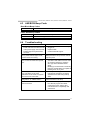
Chapter 4: Useful Help ......................................... 21
4.1 Driver Installation.............................................................................23
4.2 Extra Information.............................................................................24
4.3 AMI BIOS Beep Code.....................................................................25
4.4 Troubleshooting...............................................................................25
Appendix: SPEC In Other Languages .................... 26
Arabic.....................................................................................................................26
French ...................................................................................................................27
German .................................................................................................................28
Italian .....................................................................................................................29
Japanese...............................................................................................................30
Polish.....................................................................................................................31
Portuguese ...........................................................................................................32
Russian .................................................................................................................33
Spanish..................................................................................................................34

NM70I-847/NM70I-807/NM70I-1007U/NM70I-1037U
1
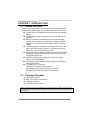
CHAPTER 1: INTRODUCTION
1.1 Before You Start
Thank you for choosing our product. Before you start installing the
motherboard, please make sure you follow the instructions below:
Prepare a dry and stable working environment with sufficient
lighting.
Always disconnect the computer from power outlet before
operation.
Before you take the motherboard out from anti-static bag,
ground yourself properly by touching any safely grounded
appliance, or use grounded wrist strap to remove the static
charge.
Avoid touching the components on motherboard or the rear
side of the board unless necessary. Hold the board on the
edge, do not try to bend or flex the board.
Do not leave any unfastened small parts inside the case after
installation. Loose parts will cause short circuits which may
damage the equipment.
Keep the computer from dangerous area, such as heat
source, humid air and water.
The operating temperatures of the computer should be 0 to
45 degrees Celsius.
To avoid injury, be careful of:
Sharp pins on headers and connectors
Rough edges and sharp corners on the chassis
Damage to wires that could cause a short circuit
1.2 Package Checklist
; Serial ATA Cable x2
; Rear I/O Panel for ATX Case x1
; Installation Guide x1
; Fully Setup Driver DVD x1
Note: The package contents may be different due to the sales region or models in which it was sold.
For more information about the standard package in your region, please contact your dealer or sales
representative.

Motherboard Manual
2
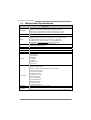
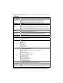
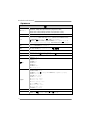
1.3 Motherboard Specifications
Specifications
CPU Support
NM70I-847: Intel® Celeron® Processor 847 (Dual Core 1.1GHz)
NM70I-807: Intel® Celeron® Processor 807 (Single Core 1.5GHz)
NM70I-1007U: Intel® Celeron® Processor 1007U (Dual Core 1.5 GHz)
NM70I-1037U: Intel® Celeron® Processor 1037U (Dual Core 1.8 GHz)
Chipset INTEL NM70
Memory
Supports Dual Channel DDR3 1066/ 1333 (NM70I-847 & NM70I-807)
Supports Dual Channel DDR3 1333/ 1600 (NM70I-1007U & NM70I-1037U)
2 x DDR3 DIMM Memory Slot, Max. Supports up to 16 GB Memory
Each DIMM supports non-ECC 512MB/ 1/ 2/ 4/ 8 GB DDR3 module
* Please refer to www.biostar.com.tw
for Memory support list.
Storage
1x SATA 6Gb/s Connector, 3x SATA 3Gb/s Connector,
Supports Native IDE, AHCI Mode
LAN Realtek RTL 8111F, 10/ 100/ 1000 Mb/s auto negotiation, Half / Full duplex capability
Audio Codec ALC662, 5.1 Channels, High Definition Audio
USB 8x USB 2.0 port (4 on rear I/Os and 4 via internal headers)
Expansion Slots 1x PCIe 2.0 x16 Slot (x8)
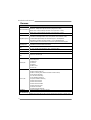
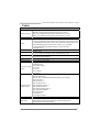
Rear I/Os
1x PS/2 Mouse
1x PS/2 Keyboard
1x HDMI Port
1x VGA Port
1x LAN port
4x USB 2.0 Port
3x Audio Jack
Internal I/Os
1x SATA 6.0Gb/s Connector
3x SATA 3.0Gb/s Connector
2x USB 2.0 Header (each header supports 2 USB 2.0 ports)
1x 4-Pin Power Connector
1x 24-Pin Power Connector
1x CPU Fan Connector
1x System Fan Connector
1x Front Panel Header
1x Front Audio Header
1x Clear CMOS Header
1x Printer Port Header
1x Serial Port Header
1x S/PDIF out Connector
Form Factor mini-ITX Form Factor, 170 mm x 170 mm
OS Support
Windows XP / Vista / 7 / 8
Biostar reserves the right to add or remove support for any OS with or without notice.

NM70I-847/NM70I-807/NM70I-1007U/NM70I-1037U
3
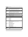
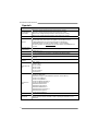
1.4 Central Processing Unit (CPU)
The motherboard is equipped with an onboard Intel processor and a CPU cooler.
Model: Onboard Intel CPU:
NM70I-847 Intel® Celeron® Processor 847 (Dual Core 1.1GHz, Sandy Bridge)
NM70I-807 Intel® Celeron® Processor 807 (Single Core 1.5GHz, Sandy Bridge)
NM70I-1007U Intel® Celeron® Processor 1007U (Dual Core 1.5 GHz, Ivy Bridge)
NM70I-1037U Intel® Celeron® Processor 1037U (Dual Core 1.8 GHz, Ivy Bridge)
1.5 Rear Panel Connectors
Note 1: Since the audio chip supports High Definition Audio Specification, the function of
each audio jack can be defined by software. The input / output function of each audio jack
listed above represents the default setting. However, when connecting external
microphone to the audio port, please use the Line In (Blue) and Mic In (Pink) audio jack.
Note 2: Maximum resolution:
VGA: 2048 x 1536 @75Hz
HDMI: 1920 x 1200 @60Hz

Motherboard Manual
4
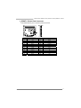
1.6 Motherboard Layout
Note: ■ represents the 1
st
pin.

NM70I-847/NM70I-807/NM70I-1007U/NM70I-1037U
5
CHAPTER 2: HARDWARE INSTALLATION
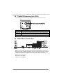
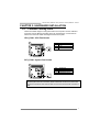
2.1 Connect Cooling Fans
These fan headers support cooling-fans built in the computer. The fan cable and
connector may be different according to the fan manufacturer. Connect the fan
cable to the connector while matching the black wire to pin#1.
CPU_FAN1: CPU Fan Header
Pin Assignment
1 Ground
2 +12V
3
FAN RPM rate sense
SYS_FAN1: System Fan Header
Pin Assignment
1 Ground
2 +12V
3
FAN RPM rate sense
Note: CPU_FAN1, SYS_FAN1 support 4-pin and 3-pin head connectors. When
connecting with wires onto connectors, please note that the red wire is the positive and
should be connected to pin#2, and the black wire is Ground and should be connected to
GND.

Motherboard Manual
6
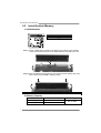
2.2 Install System Memory
A. DDR3 Modules
Step 1: Unlock a DIMM slot by pressing the retaining clips outward. Align a DIMM
on the slot such that the notch on the DIMM matches the break on the slot.
Step 2: Insert the DIMM vertically and firmly into the slot until the retaining chip snap
back in place and the DIMM is properly seated.
Note: If the DIMM does not go in smoothly, do not force it. Pull it all the way out and try again.
B. Memory Capacity
DIMM Socket Location
DDR3 Module
Total Memory Size
DDR3_A1 512MB/1GB/2GB/4GB/8GB
DDR3_B1 512MB/1GB/2GB/4GB/8GB
Max is 16GB.

NM70I-847/NM70I-807/NM70I-1007U/NM70I-1037U
7
C. Dual Channel Memory Installation
Please refer to the following requirements to activate Dual Channel function:
Install memory module of the same density in pairs, shown in the table.
Dual Channel Status DDR3_A1 DDR3_B1
Disabled O X
Disabled X O
Enabled O O
(O means memory installed, X means memory not installed.)
Note: The DRAM bus width of the memory module must be the same (x8 or x16)
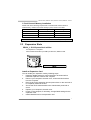
2.3 Expansion Slots
PEX16_1: PCI-Express Gen2 x8 Slot
- PCI-Express 2.0 compliant.
- Data transfer bandwidth up to 4GB/s per direction; 8GB/s in total.
Install an Expansion Card
You can install your expansion card by following steps:
1. Read the related expansion card's instruction document before
install the expansion card into the computer.
2. Remove your computer's chassis cover, screws and slot bracket
from the computer.
3. Place a card in the expansion slot and press down on the card until it
is completely seated in the slot.
4. Secure the card’s metal bracket to the chassis back panel with a
screw.
5. Replace your computer's chassis cover.
6. Power on the computer, if necessary, change BIOS settings for the
expansion card.
7. Install related driver for the expansion card.

Motherboard Manual
8
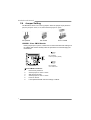
2.4 Jumper Setting
The illustration shows how to set up jumpers. When the jumper cap is placed on
pins, the jumper is “close”, if not, that means the jumper is “open”.
Pin opened Pin closed Pin1-2 closed
JCMOS1: Clear CMOS Header
Placing the jumper on pin2-3, it allows user to restore the BIOS safe setting and
the CMOS data. Please carefully follow the procedures to avoid damaging the
motherboard.
31
Pin 1-2 Close:
Normal Operation (default).
31
Pin 2-3 Close:
Clear CMOS data.
※ Clear CMOS Procedures:
1. Remove AC power line.
2. Set the jumper to “Pin 2-3 close”.
3. Wait for five seconds.
4. Set the jumper to “Pin 1-2 close”.
5. Power on the AC.
6. Load Optimal Defaults and save settings in CMOS.

NM70I-847/NM70I-807/NM70I-1007U/NM70I-1037U
9
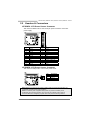
2.5 Headers & Connectors
ATXPWR1: ATX Power Source Connector
This connector allows user to connect 24-pin power connector on the ATX
power supply.
Pin Assignment Pin Assignment
13 +3.3V 1 +3.3V
14 -12V 2 +3.3V
15 Ground 3 Ground
16 PS_ON 4 +5V
17 Ground 5 Ground
18 Ground 6 +5V
19 Ground 7 Ground
20 NC 8 PW_OK
21 +5V 9 Standby Voltage+5V
22 +5V 10 +12V
23 +5V 11 +12V
24 Ground 12 +3.3V
ATXPWR2: ATX Power Source Connector
This connector will provide +12V to CPU power circuit.
Pin Assignment
1 +12V
2 +12V
3 Ground
4 Ground
Note1: Before you power on the system, please make sure that both ATXPWR1 and
ATXPWR2 connectors have been plugged-in.
Note2: Insufficient power supplied to the system may result in instability or the
peripherals not functioning properly. Use of a PSU with a higher power output is
recommended when configuring a system with more power-consuming devices.

Motherboard Manual
10
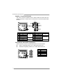
PANEL1: Front Panel Header
This 16-pin connector includes Power-on, Reset, HDD LED, Power LED, and
speaker connection. It allows user to connect the PC case’s front panel switch
functions.
Pin Assignment Function Pin Assignment Function
1 +5V 9 N/A
2N/A 10N/A
N/A
3 N/A 11 N/A N/A
4 Speaker
Speaker
Connector
12 Power LED (+)
5 HDD LED (+) 13 Power LED (+)
6 HDD LED (-)
Hard drive LED
14 Power LED (-)
Power LED
7 Ground 15 Power button
8 Reset control
Reset button
16 Ground
Power-on button
SATA1/2/3/4: Serial ATA Connectors
These connectors connect to SATA hard disk drives via SATA cables.
SATA1: Supporting SATA3, up to 6 Gb/s data transfer rate.
SATA2/3/4: Supporting SATA2, up to 3 Gb/s data transfer rate.
Pin Assignment
1 Ground
2 TX+
3 TX-
4 Ground
5 RX-
6 RX+
7 Ground

NM70I-847/NM70I-807/NM70I-1007U/NM70I-1037U
11
F_USB1/F_USB2: Headers for USB 2.0 Ports at Front Panel
This header allows user to connect additional USB cable on the PC front panel,
and also can be connected with a wide range of simultaneously accessible
external Plug and Play peripherals.
Pin Assignment
1 +5V (fused)
2 +5V (fused)
3 USB-
4 USB-
5 USB+
6 USB+
7 Ground
8 Ground
9 NC
10 Key
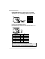
F_AUDIO1: Front Panel Audio Header
This header allows user to connect the front audio output cable with the PC front
panel. This header supports HD and AC’97 audio front panel connector.
HD Audio AC’97
Pin Assignment Pin Assignment
1 Mic Left in 1 Mic In
2 Ground 2 Ground
3 Mic Right in 3 Mic Power
4 GPIO 4 Audio Power
5 Right line in 5 RT Line Out
6 Jack Sense 6 RT Line Out
7 Front Sense 7 Reserved
8 Key 8 Key
9 Left line in 9 LFT Line Out
10 Jack Sense 10 LFT Line Out
Note1: It is recommended that you connect a high-definition front panel audio module to
this connector to avail of the motherboard's high definition audio capability.
Note2: Please try to disable the "Front Panel Jack Detection" if you want to use an
AC'97 front audio output cable. The function can be found via O.S. Audio Utility.

Motherboard Manual
12
JSPDIFOUT1: Digital Audio-out Connector
The JSPDIFOUT1 is for connecting the PCI bracket SPDIF output.
Pin Assignment
1 +5V
2 SPDIF_OUT
3 Ground
J_COM1: Serial Port Connector
The motherboard has a Serial Port Connector for connecting RS-232 Port.
Pin Assignment
1 Carrier detect
2 Received data
3 Transmitted data
4 Data terminal read
y
5Si
g
nal
g
round
6 Data set read
y
7 Request to send
8 Clear to send
9 Ring indicator
10 NC

NM70I-847/NM70I-807/NM70I-1007U/NM70I-1037U
13
J_PRINT1: Printer Port Connector
This header allows you to connector printer on the PC.
Pin Assignment Pin Assignment
1 -Strobe 14 Ground
2 -ALF 15 Data 6
3 Data 0 16 Ground
4 -Error 17 Data 7
5 Data 1 18 Ground
6 -Init 19 -ACK
7 Data 2 20 Ground
8 -Scltin 21 Busy
9 Data 3 22 Ground
10 Ground 23 PE
11 Data 4 24 Ground
12 Ground 25 SCLT
13 Data 5 26 Key

Motherboard Manual
14
CHAPTER 3: UEFI BIOS & SOFTWARE
3.1 UEFI BIOS Setup
z For better system performance, the UEFI BIOS firmware is being
continuously updated. The UEFI BIOS information described below in this
manual is for your reference only and the actual UEFI BIOS information and
settings on board may be different from this manual
z For further information of setting up the UEFI BIOS, please refer to the UEFI
BIOS Manual in the Setup DVD.
3.2 BIOS Update
z BIOSTAR BIOS Flasher: Using this utility, the BIOS can be updated from a
file on a hard disk, a USB drive (a flash drive or a USB hard drive), or a
CD-ROM.
z BIOSTAR BIOS Update Utility: It enables automated updating while in the
Windows environment. Using this utility, the BIOS can be updated from a file
on a hard disk, a USB drive (a flash drive or a USB hard drive), or a
CD-ROM, or from the file location on the Web.
BIOSTAR BIOS Flasher
BIOSTAR BIOS Flasher is a BIOS flashing utility providing you an easy and simple
way to update your BIOS via USB pen drive.
Note1: This utility only allows storage device with FAT32/16 format and single partition.
Note2: Shutting down or resetting the system while updating the BIOS will lead to system boot
failure.
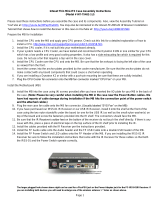
Updating BIOS with BIOSTAR BIOS Flasher
1. Go to the website to download the latest BIOS file for the motherboard.
2. Then, copy and save the BIOS file into a USB flash (pen) drive.
3. Insert the USB pen drive that contains the BIOS file to the USB port.
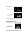
4. Power on or reset the computer and then press <F12> during the POST process.
5. After entering the POST screen,
the BIOS-FLASHER utility pops
out. Choose [fs0] to search for the
BIOS file.

NM70I-847/NM70I-807/NM70I-1007U/NM70I-1037U
15
6. Select the proper BIOS file, and a
message asking if you are sure to
flash the BIOS file. Click Yes to
start updating BIOS.
7. A dialog pops out after BIOS flash
is completed, asking you to restart
the system. Press the [Y] key to
restart system.
8. While the system boots up and the full screen logo shows up, press <DEL> key to
enter BIOS setup.
After entering the BIOS setup, please go to the Save & Exit, using the Restore
Defaults function to load Optimized Defaults, and select Save Changes and
Reset to restart the computer. Then, the BIOS Update is completed.
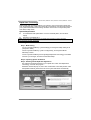
BIOS Update Utility (through the Internet)
1. Installing BIOS Update Utility from the DVD Driver.
2. Please make sure the system is connected to the internet before using this
function.
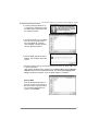
3. Launch BIOS Update Utility and
click the Online Update button on
the main screen.

Motherboard Manual
16
4. An open dialog will show up to
request your agreement to start the
BIOS update. Click Yes to start the
online update procedure.
5. If there is a new BIOS version, the
utility will ask you to download it.
Click Yes to proceed.
6. After the download is completed,
you will be asked to program
(update) the BIOS or not. Click Yes
to proceed.
7. After the updating process is
finished, you will be asked you to
reboot the system. Click OK to
reboot.
8. While the system boots up and the full screen logo shows up, press <DEL> key
to enter BIOS setup.
After entering the BIOS setup, please go to the Save & Exit, using the Restore
Defaults function to load Optimized Defaults, and select Save Changes and
Reset to restart the computer. Then, the BIOS Update is completed.
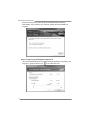
BIOS Update Utility (through a BIOS file)
1. Installing BIOS Update Utility from the DVD Driver.
2. Download the proper BIOS from http://www.biostar.com.tw/
3. Launch BIOS Update Utility and
click the Update BIOS button on
the main screen.

NM70I-847/NM70I-807/NM70I-1007U/NM70I-1037U
17
4. A warning message will show up
to request your agreement to start
the BIOS update. Click OK to start
the update procedure.
5. Choose the location for your BIOS
file in the system. Please select
the proper BIOS file, and then
click on Open. It will take several
minutes, please be patient.
6. After the BIOS Update process is
finished, click on OK to reboot the
system.
7. While the system boots up and the full screen logo shows up, press <DEL> key
to enter BIOS setup.
After entering the BIOS setup, please go to the Save & Exit, using the Restore
Defaults function to load Optimized Defaults, and select Save Changes and
Reset to restart the computer. Then, the BIOS Update is completed.
Backup BIOS
Click the Backup BIOS button on
the main screen for the backup of
BIOS, and select a proper location
for your backup BIOS file in the
system, and click Save.

Motherboard Manual
18
3.3 Software
Installing Software
1. Insert the Setup DVD to the optical drive. The driver installation program would
appear if the Autorun function has been enabled.
2. Select Software Installation, and then click on the respective software title.
3. Follow the on-screen instructions to complete the installation.
Note1: All the information and content about following software are subject to be changed without
notice. For better performance, the software is being continuously updated.
Note2: The information and pictures described below are for your reference only. The actual
information and settings on board may be slightly different from this manual.
Launching Software
After the installation process is completed, you will see the software icon showing on
the desktop. Double-click the icon to launch it.
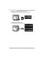
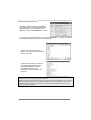
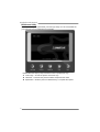
eHot-Line
eHot-Line is a convenient utility that helps you to contact with our Tech-Support
system. This utility will collect the system information which is useful for analyzing the
problem you may have encountered, and then send these information to our
tech-support department to help you fix the problem.
Note: Before you use this utility, please set Outlook Express as your default e-mail client
application program.
This block will show
the i nfor mati on which
would be collected in
the mail.
Provid e the e-mail
address that you would
like to send the copy to.
Provid e the name of
the power supply
manufacturer and the
model no.
Send the mail out.
Save these information to a .txt fil
e
Exit this dialog.
Select your area or
the area close to you.
*
Provid e the name of
the memory module
manufacturer.
*
Describe condition
of your system.
*
*
represents important
infor ma tion that you
must provide. Without
this information, you may
not be able to send out
the mail.
Page is loading ...
Page is loading ...
Page is loading ...
Page is loading ...
Page is loading ...
Page is loading ...
Page is loading ...
Page is loading ...
Page is loading ...
Page is loading ...
Page is loading ...
Page is loading ...
Page is loading ...
Page is loading ...
Page is loading ...
Page is loading ...
-
 1
1
-
 2
2
-
 3
3
-
 4
4
-
 5
5
-
 6
6
-
 7
7
-
 8
8
-
 9
9
-
 10
10
-
 11
11
-
 12
12
-
 13
13
-
 14
14
-
 15
15
-
 16
16
-
 17
17
-
 18
18
-
 19
19
-
 20
20
-
 21
21
-
 22
22
-
 23
23
-
 24
24
-
 25
25
-
 26
26
-
 27
27
-
 28
28
-
 29
29
-
 30
30
-
 31
31
-
 32
32
-
 33
33
-
 34
34
-
 35
35
-
 36
36


Biostar NM70I-1037U User manual
- Category
- Motherboards
- Type
- User manual
- This manual is also suitable for
Ask a question and I''ll find the answer in the document
Finding information in a document is now easier with AI
Related papers
-
Biostar AM1MHP Quick start guide
-
-
-
-
-
Biostar H81MHP Ver. 6.x User manual
-
Biostar Hi-Fi H61S3L Owner's manual
-
Biostar H81MGP2 Ver. 6.x User manual
-
-
Biostar A78MD 6.0 User manual