Cobra 29 LTD CHR User manual

Category
Two-way radios
Type
User manual

This manual is also suitable for

How to Use Your
Cobra 29 LTD CHR
Contents
Features..................................................................................................1
The CB Story.........................................................................................A1
FCC Regulations
FCC Warnings
Included Accessories
Controls & Indicators.......................................................................A2
Our Thanks to You .............................................................................A3
Customer Support
Installation
Location .............................................................................................2
Mounting and Connection .........................................................2
Antennas
CB Antenna.......................................................................................6
Marine Installation .........................................................................6
Ignition Noise Interference ..........................................................7
Operating Your 29 LTD CHR
Turning On Your CB........................................................................8
Setting Channel Selector .............................................................9
Calibrate For SWR (Standing Wave Ratio)..............................10
To Receive..........................................................................................13
Selecting a Channel.......................................................................14
S-Meter ...............................................................................................14
NB-ANL/ANL/Off (Noise Blanker/Automatic.........................15
Noise Limiter Switch)
Bright/Dim Switch ..........................................................................16
RF Gain Control................................................................................17
Setting Delta-Tune .........................................................................18
Setting Squelch...............................................................................18
To Transmit........................................................................................20
Setting Dynamike® ........................................................................20
Transmit..............................................................................................21
TalkBack..............................................................................................21
RF Meter .............................................................................................22
External Speaker .............................................................................23
PA (Public Address) ........................................................................24
Home And Office Set-Up .............................................................26
Temporary Mobile Set-Up ...........................................................27
How Your CB Can Serve You..........................................................28
A Few Rules You Should Know..................................................28
Channel 9 Emergency Messages..............................................28
CB 10 Codes......................................................................................30
Frequency Ranges.............................................................................32
29 LTD CHR Specifications ............................................................33
Warranty Information .....................................................................34
Optional Accessories .................................................................35-36
Accessory Order Info .......................................................................37
If You Think You Need Service...................................Back Cover
Features of This Product
40 CB Radio Channels
Special Edition Chrome Cabinet
& Microphone
Heavy-Duty Dynamic
Microphone
Full 4 Watts AM RF Power Output
SWR Calibration Meter
Talk Back
Instant Channel 9
4-Pin Front Mount Microphone
Connector
Delta -Tune
Switchable Automatic Noise
Limiter & Noise Blanker
Adjustable Dynamike® Boost
9 Ft. Mic Cord
RF Gain
1
Installation
Installation
Location
32
Mounting and
Connection
Mounting and Connection
Hold the radio with the mounting bracket in
the exact desired location. If there is no
interference, remove the bracket and use it as
a template to mark the location for the
mounting screws.
Location
Plan location of transceiver and microphone
bracket before starting the installation.
Select a location that is convenient for operation,
yet does not interfere with the driver or passenger.
The transceiver is usually mounted to the
underside of the dash with the microphone
bracket beside it.
Note
The transceiver is held in
the universal mounting bracket
by two thumbscrews which
allow for adjustment at a
convenient angle.
The bracket includes two
self-tapping screws and star
washers.The mounting must be
mechanically strong,
conveniently located.
continued
Drill the holes and secure the bracket.
2
1
Connect the antenna cable plug to the
receptacle markedANT on the back of
the unit.
3
Installation
Installation
54
Note
Connecting to an accessory fuse
prevents the unit from being left
on accidentally, and also
permits operating the unit
without running the engine.
Note
In positive ground vehicles the
red wire goes to the chassis and
the black wire is connected to
the ignition switch.
Note
Before installing the CB radio,
visually check the vehicle’s
battery connection to
determine which terminal,
positive or negative, is
grounded (positive is the
larger of the two) to the
engine block (or chassis). A
negatively grounded vehicle
has its negative lead
grounded to the chassis.
In a negative grounded vehicle, connect the
red lead of the DC power cord to an accessory
12 volt fuse.
Connect the black lead to the negative side of
the vehicle.This is usually the chassis. Any
convenient location with a good electrical
contact (remove paint) may be used.
4
5
Plug power cable into back of unit marked
“Power”. Be sure to observe polarity markings.
Mount the microphone
bracket on either side of
the unit (driver’s left)
using two screws
supplied. Bracket should
be placed under the dash
so microphone is readily
accessible.
6
7
Attach the 4-pin microphone cable to
receptacle, on the front of unit and install unit
on bracket securely.
8
Ignition Noise Interference
Antennas
Use of a mobile receiver at low signal levels is
normally limited by the presence of electrical
noise.The primary source of noise in automobiles
is from the alternator and ignition system.
Typically, when signal level is adequate, the
background noise does not present a serious
problem. Also, when extremely low level signals
are being received, the transceiver may be
operated with the vehicles engine turned off.The
unit requires very little current and therefore will
not significantly discharge the vehicles battery.
Even though the Cobra 29 LTD CHR has an
automatic noise limiter, in some installations
ignition interference may be high enough to
make good communications impossible. Many
possibilities exist and variations between vehicles
require different solutions. Consult your COBRA
dealer or a 2-way radio technician for help in
locating the source of a severe noise.
CB Antenna
Since the maximum allowable power output of
the transmitter is limited by the FCC, the antenna
is critical in affecting transmission distance. Only
a properly matched antenna system will allow
maximum power output. Cobra loaded type
antenna models are highly recommended for
most installations. Consult your Cobra dealer for
further details, or call 773.889.3087 and speak to
a Cobra representative.
Marine Installation
The transceiver will not operate at maximum
efficiency in a boat without a ground plate,
(unless it has a steel hull). Before attempting
installation , consult your dealer for information
regarding an adequate grounding system and
prevention of electrolysis between fittings in the
hull and water.
CB Antenna
7
Note
For optimum performance in
passenger cars the ideal
antenna location is on the
center of the roof. Second
choice is on the
center of the trunk.
Note
Because many newer trucks
feature fiberglass door skins, the
outside mirror must be
grounded to the chassis via a
ground strap when antenna is
mounted on the mirror bracket.
Note
3-way Combination
Antennas are also available
which allow operation of all
three bands (AM-FM & CB),
using a single antenna.
However, this type of antenna
usually results in less than
normal transmit and receive
range when compared to a
standard-type “Single Band” CB
antenna. Call 773-889-3087 for
further information.
6
1
A standard antenna connector is provided
on the transceiver for easy connection.
The CB/PA button should be in the
CB position.
Operation
9
Operation
Turning On Setting Channel
Selector
8
Turning On
Make sure the power cord, antenna and
microphone are connected to their proper
connectors before starting.
Setting Channel Selector
2
1
Rotate the On/Off Volume knob clockwise to
a normal listening level.
Select one of forty channels and adjust
volume.The selected channel is indicated by
the LED readout directly above the channel
selector knob
1
Operation
Operation
Calibrate For
SWR (Standing
Wave Ratio)
1110
Note
Antenna Indicator LED
will illuminate when TX if
SWR is high.
Note
Calibration must be made in an
open area (never in a garage).
Vehicle doors must be closed.
No one should be standing near
the antenna. (See your antenna
directions for more complete
information).
continued
Switch to the CAL position.
2
1
Calibrate for SWR (Standing Wave Ratio)
SWR calibration is done to properly adjust the
length of the antenna and to monitor the quality
of the coaxial cable and all RF connections.
This calibration is critical in order to achieve
optimum performance.
Select channel 20.
Push and hold mic button.
3
While holding mic
button adjust the
SWR CAL knob so the
meter needle swings
to the CAL mark on
the meter (located on the right).
4
Operation
13
Operation
12
Note
The reading will be slightly
higher on Channels 1 and 40
compared to Channel 20.
Note
When switched to SWR position
the meter needle should ideally
be as far to the left as possible.
Anything over 3 is not
acceptable.The antenna
indicator will light. A slight
antenna height adjustment
(higher or lower) may be
required.Repeat relcalibration
steps.
Repeat the same steps two through five
on Channel 1 and 40. This will check SWR for
all channels.
6
While still holding down the mic button, set
the S/RF SWR CAL switch to the SWR position,
to read the SWR reading.
5
Rotate the On/Off Volume knob clockwise
the green RX/TX LED will be illuminated.
To Receive
1
To Receive
The S/RF-SWR-CAL switch must be in the
S/RF position to read the meter.
Operation
15
Operation
14
1
S-Meter
S-Meter
Swings proportionately to strength of incoming
signal when receiving.
Switch to NOR to select desired channel.
1
Selecting A
Channel
Selecting A Channel
NB-ANL/ANL/
OFF (Noise
Blanker/
Automatic
Noise Limiter)
Switch
Note
The RF noise blanker is very
effective in reducing repetitive
noises such as ignition
interference.
When switched to ANL the Automatic Noise
Limiter is activated.This helps reduce noise
created by the vehicles electronics.
When switched to NB/ANL position the RF
Noise Blanker is also activated, providing
increased noise filtration.
When switched to OFF position all noise
filtration will be turned off.
NB-ANL/ANL/OFF (Noise
Blanker/Automatic Noise Limiter) Switch
1
Operation
Operation
1716
RF Gain Control
Bright/Dim
Switch
RF Gain Control
The RF Gain is used to optimize reception in
strong or weak signal areas.
Bright/Dim Switch
Note
The RF Gain is used to optimize
reception in weak signal areas.
Switch to BRT or DIM to control brightness
of the channel indicator and multi-function
meter for day or nighttime driving.
Rotate the RF Gain knob counterclockwise
to reduce gain in strong signal areas. In weak
signal areas turn clockwise to increase gain.
1
1
Full clockwise rotation closes the gate
allowing only very strong signals to enter.
Full counterclockwise rotation opens the
gate”allowing all signals in.
To achieve the Desired Squelch Setting (DSS),
turn the Squelch control counterclockwise
until you hear noise. Now turn the control
clockwise just until the noise stops. This is the
DSS setting.
Setting Delta-Tune
Delta-Tune functions as a “fine tune” control
enabling you to capture a more readable signal,
as well as eliminate adjacent channel interference.
Setting Squelch
Squelch is the control gate”for incoming signals.
19
Setting
Delta-Tune
18
Operation
Operation
1
2
1
3
Rotate Delta-Tune knob to the center
position for optimum tuning.
Gate open
Gate set to Desired
Squelch Setting (DSS)
Gate closed
Setting Squelch
Setting Dynamik
This controls the microphone sensitivity
(outgoing audio level).
To Transmit
21
To Transmit Transmit
TalkBack
20
Setting
Dynamike®
Caution!
Be sure the antenna is properly
connected to the radio before
transmitting. Prolonged
transmitting without an
antenna, or a poorly matched
antenna, could cause damage
to the transmitter.
Be sure to read the F.C.C. Rules
and Regulations included with
this unit before transmitting.
Operation
Operation
1
Select desired channel.
1
Initially, set fully clockwise so that maximum
voice volume is available. Dynamike® may have
to be reduced in some conditions.
Transmit
Push and hold mic button to transmit.Transmitter
is now activated.When transmitting,hold the
microphone two inches from your mouth and
speak in a clear, normal voice. Release to receive.
1
Setting TalkBack
This control is used to adjust the desired amount
of modulation talk back that is present at the
speaker during transmit. At fully counter-clockwise
position the talk back is off.
Operation
Operation
RF Meter
23
22
External Speaker
RF Meter
This meter swings proportionately to the RF
output (outgoing signal) while transmitting.
External Speaker
The external speaker jack is used for remote
receiver monitoring.
The S/RF-SWR-CAL switch must be in the
S/RF position.
1
Note
The external speaker should
have 8-ohm impedance and be
rated to handle at least 4.0
watts.When the external
speaker is plugged in, the
internal speaker is
automatically disconnected.
Note
Cobra external speakers are
rated at 10 watts.
Connect an external speaker to the external
speaker jack on the rear panel.
1
Operation
Operation
PA (Public
Address)
2524
PA (Public Address)
Connect an external PA speaker to the PA jack
on the rear panel.
Set CB/PA switch to PA position.
Push and hold microphone button and speak
in a normal voice.Your voice will now transmit
on the PA speaker.
Adjust PA speaker volume with the
Dynamik control.
Note
Speaker should have 8-ohm
impedance and be rated to
handle at least 4.0 watts.
Note
The speaker should be directed
away from the microphone to
prevent acoustic feedback.
Note
Activity on the CB channel will
be heard through the PA
speaker. Adjust volume control
to a normal listening level.
1
2
3
4
Temporary Mobile Set-Up
27
Base Station
Operation
(From 120V AC
House Current)
Temporary
Mobile Set-Up
Temporary Mobile Operation
For temporary mobile operation you may want to
purchase an optional automobile power adapter
from your COBRA dealer.This adapter and a
magnetic mount antenna allow you to quickly
“install” your transceiver for temporary use.
Base Station Operation
(From 120V AC House Current)
To operate your transceiver from home or office
you will need a 13.8 volt DC Power Pack rated at a
minimum of 2 amps, and a properly installed base
station antenna.
Home And Office Set-Up
26
Warning!
Do not attempt to operate this
transceiver by connecting it
directly to 120v ac.
Note
For further information call
Cobra Customer Service
773.889.3087.
1
Connect properly installed and matched base
station antenna.
Simply connect the red (+) and black (-)
leads of the transceiver to the corresponding
terminals of the power pack.
Plug power cable into back of unit marked
“Power”. Be sure to observe polarity markings.
2
3
How Your CB Can Serve You
2928
The FCC gives these examples of permitted and
prohibited messages for channel 9. These are
only guidelines and not all-inclusive:
Permitted Example Message
Yes Tornado sighted six miles north
of town.”
No “Post number 10.
No tornado sighted.”
Yes “Out of gas on I-95 at mile
marker 211.”
No “Out of gas in my driveway.
Yes “Four car accident on I-94 at
Exit 11. Send police and
ambulance.”
No Traffic moving smoothly on I-94.”
Yes Weather Bureau has issued
thunderstorm warning.
Bring sailboat into port.”
No Attention motorists.
Weather Bureau advises snow
tomorrow will accumulate
4 to 6 inches.”
Yes “Fire in building at 539 Main,
Evanston.”
No “Halloween patrol number 3.
All quiet.
1. Set to channel 9 for emergencies
Be sure antenna is properly connected.
2. CB Distress Data
When transmitting an emergency, you should
request a “REACT BASE” and provide the CB
distress data (called CLIP):
C all Sign Identify yourself.
L ocation Be exact.
I njuries Number.Type.Trapped?
P roblem Give details and help needed.
Transmit CLIP repeatedly so any monitor can assist.
Channel 9
Emergency
Messages
Note
If no response on channel 9,
try channels 19 or 14.
Warn of traffic problems
Provide weather and road data
Provide help in event of an emergency
Provide direct contact with home or office
Assist police by reporting erratic drivers
Get “local informationto find destination
Communicate with family and friends
Suggest spots to eat and sleep
Keep you alert while traveling
A Few Rules You Should Know
A. Conversations cannot last more than 5 minutes
with another station. A one minute break is
required to let others use the channel.
B. You cannot blast others off the air by use of
illegally amplified transmitters or illegally
high antennas.
C. You cannot use CB to promote illegal activities.
D. Profanity is not allowed.
E. You may not transmit music with a CB.
F. Selling of merchandise and/or services is
prohibited.
A Few Rules
You Should
Know
How Your CB Can Serve You
3130
Code Meaning
10-29 Time is up for contact
10-30 Does not conform to FCC rules
10-33 Emergency traffic
10-34 Trouble at this station
10-35 Confidential information
10-36 Correct time is
10-37 Wrecker needed at
10-38 Ambulance needed
10-39 Message delivered
10-41 Turn to channel
10-42 Traffic accident at
10-43 Traffic tie up at
10-44 Have a message for
10-45 All units within range please report
10-50 Break channel
10-60 What is next message number?
10-62 Unable to copy. Use phone
10-63 Net directed to
10-64 Net clear
10-65 Awaiting your next message/assignment
10-67 All units comply
10-70 Fire at
10-71 Proceed, transmission in sequence
10-77 Negative contact
10-81 Reserve hotel room for
10-82 Reserve room for
10-85 My address is
10-91 Talk closer to mic
10-93 Check my frequency on this channel
10-94 Give me a long count
10-99 Mission completed, all units secure
10-200 Police needed at
CB 10-Codes
Citizen Bands have adopted the 10-CODES for
standard questions and answers. These codes
provide quick and easy communication, especially
in noisy areas. Following are some of the more
common codes and meanings:
Code Meaning
10-1 Receiving poorly
10-2 Receiving well
10-3 Stop transmitting
10-4 OK, message received
10-5 Relay message
10-6 Busy, stand by
10-7 Out of service, leaving
10-8 In service, subject to call
10-9 Repeat message
10-10 Transmission completed standing by
10-11 Talking too rapidly
10-12 Visitors present
10-13 Advise weather/roads
10-16 Make pick up at
10-17 Urgent business
10-18 Anything for us?
10-19 Return to base
10-20 My location is
10-21 Call by phone
10-22 Report in person to
10-23 Stand by
10-24 Completed last assignment
10-25 Can you contact
10-26 Disregard last info
10-27 Moving to channel
10-28 Identify your station
CB 10-Codes
29 LTD CHR Specifications
Frequency Ranges
3332
G
ENERAL
Channels . . . . . . . . . . . . . . . . . . . . . . . . . . CB - 40 CH
Frequency Range . . . . . . . . . . . . . . . . . . CB - 26.965 to 27.405 MHz
F
requency Tolerance . . . . . . . . . . . . . . . 0.005 %
Frequency Control . . . . . . . . . . . . . . . . . PLL (phase lock loop) Synthesizer
Operating Temperature Range . . . . . -30° C to + 50° C
Microphone . . . . . . . . . . . . . . . . . . . . . . . Plug-in dynamic
Input Voltage . . . . . . . . . . . . . . . . . . . . . . 13.8VDC nom. (positive or negative ground)
Current Drain . . . . . . . . . . . . . . . . . . . . . Transmit: AM full mod., 1.5A (maximum)
Receive: Squelched, 0.3A;
full audio output, 1.2A (nominal)
Size . . . . . . . . . . . . . . . . . . . . . . . . . . . . . .8-5/8”D x 7-9/32” W x 2-13/64” H
Weight . . . . . . . . . . . . . . . . . . . . . . . . . . . .4 lbs.
Antenna Connector . . . . . . . . . . . . . . . .UHF; SO-239
Meter . . . . . . . . . . . . . . . . . . . . . . . . . . . . . .Illuminated; indicates relative power output,
received signal strength and VSWR
TRANSMITTER
Power Output . . . . . . . . . . . . . . . . . . . . . .4 watts
Modulation . . . . . . . . . . . . . . . . . . . . . . . .AM (Amplitude Modulation)
Frequency Response . . . . . . . . . . . . . . .300 to 3000 Hz
Output Impedance . . . . . . . . . . . . . . . . .50 ohms, unbalanced
RECEIVER
Sensitivity . . . . . . . . . . . . . . . . . . . . . . . . .Less than 1 µV for 10 dB (S+N) /N
Selectivity . . . . . . . . . . . . . . . . . . . . . . . . .6 dB @ 7 KHz, 60 dB @ 10KHz
Image Rejection . . . . . . . . . . . . . . . . . . .80 dB, typical
Adjacent-Channel Rejection . . . . . . . .60 dB, typical
IF Frequencies . . . . . . . . . . . . . . . . . . . . .Double Conversion: 1st: 10.695 MHz
2nd: 455 KHz
Automatic Gain Control (AGC) . . . . . .Less than 10 dB change in audio output for
inputs from 10 to 50,000 microvolts
RF Gain Control . . . . . . . . . . . . . . . . . . . .Adjustable for optimum signal reception
Noise Blanker . . . . . . . . . . . . . . . . . . . . . .RF type
Squelch . . . . . . . . . . . . . . . . . . . . . . . . . . . .Adjustable;threshold less than 1µV
Audio Output Power . . . . . . . . . . . . . . .4 watts
Frequency Response . . . . . . . . . . . . . . .300 to 3000 Hz
Distortion . . . . . . . . . . . . . . . . . . . . . . . . . .Less than 5% @3 watts @ 1000 Hz
Built-in Speaker . . . . . . . . . . . . . . . . . . . .8 ohms, 5w
External Speaker (Not supplied) . . . . . .8 ohms;disables internal speaker
when connected
PA SYSTEM
Power Output . . . . . . . . . . . . . . . . . . . . . .4 watts into external speaker
External Speaker for PA . . . . . . . . . . . . .8 ohms, when PA-CB switch is in PA,
(Not Supplied) . . . . . . . . . . . . . . . . . . . . .The PA speaker also monitors the receiver;
separate jack provided
(SPECIFICATIONS SUBJECT TO CHANGE WITHOUT NOTICE)
WARNING: This product contains lead, a chemical known to the State of California
to cause cancer and birth defects or other reproductive harm..
Wash hands after handling.
The COBRA 29 LTD CHR transceiver represents one
of the most advanced AM two-way radios used as a
Class D station in the Citizens Radio Service.This
unit features advanced Phase Lock Loop (PLL)
circuitry providing complete coverage of all 40
CB channels.
1 26.965 21 27.215
2 26.975 22 27.225
3 26.985 23 27.255
4 27.005 24 27.235
5 27.015 25 27.245
6 27.025 26 27.265
7 27.035 27 27.275
8 27.055 28 27.285
9 27.065 29 27.295
10 27.075 30 27.305
11 27.085 31 27.315
12 27.105 32 27.325
13 27.115 33 27.335
14 27.125 34 27.345
15 27.135 35 27.355
16 27.155 36 27.365
17 27.165 37 27.375
18 27.175 38 27.385
19 27.185 39 27.395
20 27.205 40 27.405
Channel Channel
CB Freq. CB Freq.
Channel In MHz Channel In MHz
Optional Accessories
35
Replacement DC Power Cord
For in vehicle use
426-002-N-001
Replacement Mounting
Bracket
For in vehicle use
251-353-9-001
Replacement Thumb Screws
For in vehicle use
634-081-9-001
Replacement Microphone
Bracket
For in vehicle use
741-080-9-001
Limited One Year Warranty
34
COBRA ELECTRONICS CORPORATION warrants that
its COBRA CB Radios, and the component parts thereof,
will be free of defects in workmanship and materials for
period of one (1) year from the date of first consumer
purchase.This warranty may be enforced by the first
consumer purchaser, provided that the product is utilized
within the U.S.A.
COBRA will, without charge, repair or replace, at its
option, defective CB radios, products or component parts
upon delivery to the COBRA factory Service Department,
accompanied by proof of the date of first consumer
purchase, such as a duplicated copy of a sales receipt.
You must pay any initial shipping charges required to ship
the product for warranty service, but the return charges
will be at Cobra's expense, if the product is repaired or
replaced under warranty.
This warranty gives you specific legal rights, and you may
also have other rights which vary from state to state.
Exclusions: This limited warranty does not apply;
1) to any product damaged by accident; 2) in the
event of misuse or abuse of the product or as a result of
unauthorized alterations or repairs; 3) if the serial number
has been altered, defaced or removed; 4) if the owner of
the product resides outside the U.S.A.
All implied warranties, including warranties of
merchantability and fitness for a particular purpose
are limited in duration to the length of this warranty.
COBRA shall not be liable for any incidental,
consequential or other damages; including, without
limitation, damages resulting from loss of use or cost of
installation.
Some states do not allow limitations on how
long an implied warranty lasts and/or do not
allow the exclusion or limitation of incidental or
consequential damages, so the above limitations
may not apply to you.
Cobra Electronics
Corporation
6500 West Cortland Street
Chicago, Illinois 60707 USA
www.cobra.com
21” Base Loaded Magnet
Mount Antenna
HG A1000
38” Base Loaded Magnet
Mount Antenna
HG A1500
4 Pin Premium Noise-
Cancelling Microphone
HG M84
4 Pin Premium Noise-
Cancelling Microphone
Wood Grain
HG M84W
36
Optional Accessories cont.
4 Pin Replacement Dynamic
Microphone
HG M73
4 Pin Noise Canceling
Microphone
HG M77
Dynamic External Speaker
HG S100
Noise Canceling External
Speaker
HG S300
Noise Canceling With Talk
Back External Speaker
HG S500
Power Microphone
HG M75
Optional Accessories
You can find quality Cobra products and
accessories at your local Cobra dealer, or in the
U.S.A., you can order directly from Cobra. See
ordering info on page 37.
The Citizens Band lies between the shortwave
broadcast and 10-meter Amateur radio bands,
and was established by law in 1949. The Class D
two-way communications service was opened in
1959. (CB also includes a Class A citizens band
and Class C remote control frequencies.)
FCC Regulations
FCC regulations permit only “transmissions”
(one party to another) rather than “broadcasts”
(to a wide audience). Thus, advertising is not
allowed on CB Channels because that is
“broadcasting.”
FCC Warnings
All transmitter adjustments other than those
supplied by the manufacturer as front panel
operating controls, must be made by, or under
the supervision of, the holder of an FCC-issued
general Radio-Telephone Operator’s License.
Replacement or substitution of transistors, regular
diodes or other parts of a unique nature, with
parts other than those recommended by Cobra,
may cause violation of the technical regulations
of Part 95 of the FCC Rules, or violation of Type
Acceptance requirements of Part 2 of the Rules.
You should read and understand Part 95 (included
with this unit) of the FCC Rules and Regulations,
before operating your Cobra radio, even though
the FCC no longer requires you to obtain an
operator’s license.
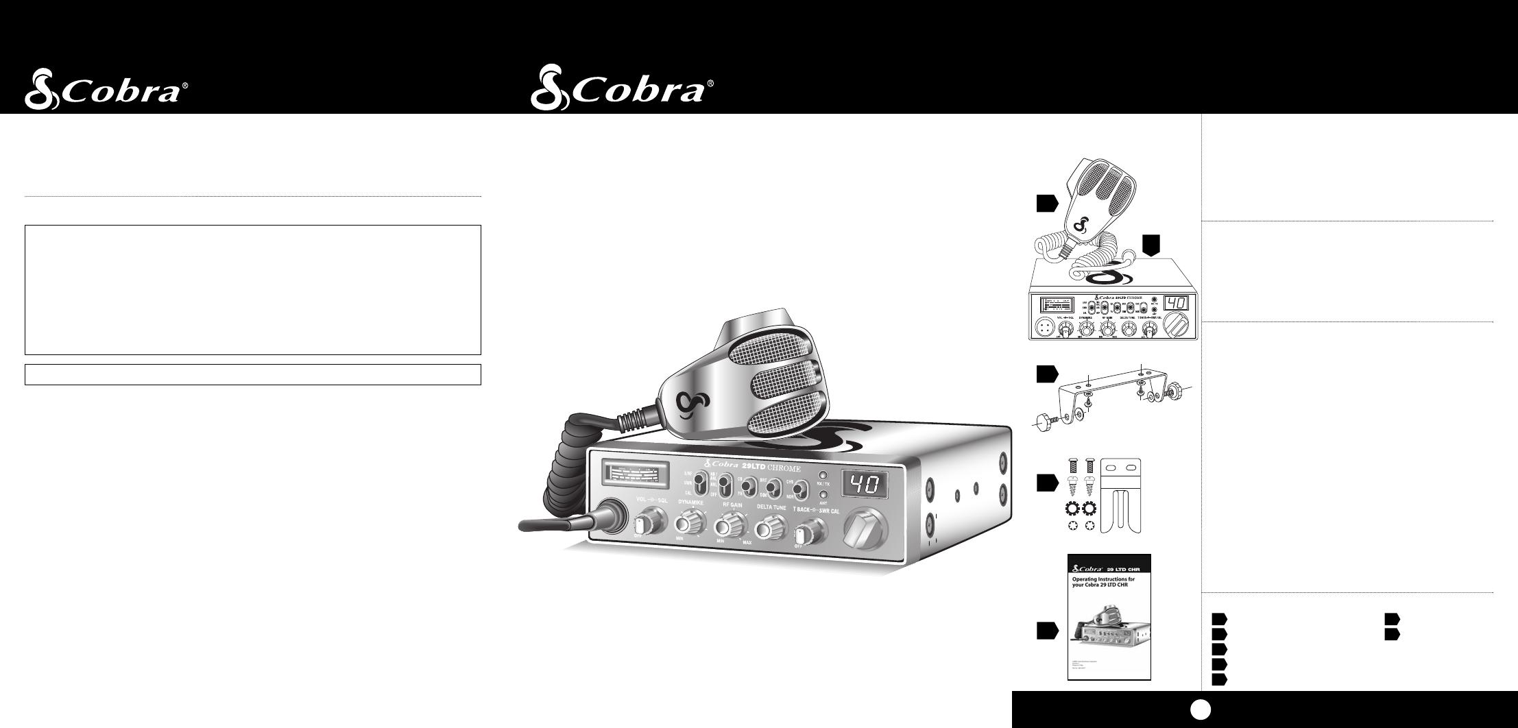
What’s Included with Your 29 LTD CHR
1. CB transceiver 6. DC power cord
2. Microphone 7. FCC rules
3. Transceiver bracket 1. (not shown)
4. Microphone bracket
5. Operating Manual
29 LTD CHR
Cobra Electronics Corporation
6500 West Cortland Street
Chicago, IL 60707 USA
©2008 Cobra Electronics Corporation
Version A
Printed in China
Part No. 480-456-P
Operating Instructions for
your Cobra 29 LTD CHR
The CB Story
A1
For technical assistance,please call our Automated Help Desk which can assist
you by answering the most frequently asked questions about Cobra products.
(773) 889-3087
24 hours a day, 7 days a week.
A Consumer Service Representative can be reached at 773.889.3087
8:00 am - 6:00 pm, Monday through Friday, Central Time.
Technical assistance is also available on-line in the Frequently Asked Questions
(FAQ) section at www.cobra.com or by e-mail to productinfo@cobra.com
If you think you need service call 773.889.3087
“If your product should require factory service please call Cobra first before sending your unit in.
This will ensure the fastest turn-around time on your repair.”
You may be asked to send your unit to the Cobra factory. It will be necessary to furnish the
following in order to have the product serviced and returned.
1. For Warranty Repair include some form of proof-of-purchase, such as a mechanical reproduction
or carbon or a sales receipt. If you send the original receipt it cannot be returned.
2. Send the entire product.
3. Enclose a description of what is happening with the unit. Include a typed or clearly print name
and address of where the unit is to be returned.
4. Pack unit securely to prevent damage in transit. If possible, use the original packing material.
5. Ship prepaid and insured by way of a traceable carrier such as United Parcel Service (UPS) or
First Class Mail: to avoid loss in transit to: Cobra Factory Service, Cobra Electronics Corporation,
6500 West Cortland Street, Chicago, IL 60707 USA.
6. If the unit is in warranty, upon receipt of your unit it will either be repaired or exchanged
depending on the model. Please allow approximately 3 to 4 weeks before contacting us for
status. If the unit is out of warranty a letter will automatically be sent informing you of the
repair charge or replacement charge. If you have any questions, please call 773.889.3087 for
assistance.
If You Think You Need Service
3
2
4
5
1
Cobra®, Dynamike®, Nothing Comes Close to a Cobra® and the snake design are registered
trademarks of Cobra Electronics Corporation, USA.
Cobra Electronics Corporation™ is a trademark of Cobra Electronics Corporation, USA.
  • Page 1 1
  • Page 2 2
  • Page 3 3
  • Page 4 4
  • Page 5 5
  • Page 6 6
  • Page 7 7
  • Page 8 8
  • Page 9 9
  • Page 10 10
  • Page 11 11
  • Page 12 12
  • Page 13 13
  • Page 14 14
  • Page 15 15
  • Page 16 16
  • Page 17 17
  • Page 18 18
  • Page 19 19
  • Page 20 20
  • Page 21 21

Cobra 29 LTD CHR User manual

Category
Two-way radios
Type
User manual
This manual is also suitable for

Ask a question and I''ll find the answer in the document

Finding information in a document is now easier with AI