Page is loading ...

THERMASREG
®
RTR -E - UP
D G F r
Herzlichen Glückwunsch!
Sie haben ein deutsches Qualitätsprodukt erworben.
Congratulations!
You have bought a German quality product.
Félicitations !
Vous avez fait l’acquisition d’un produit allemand de qualité.
Примите наши поздравления !
Вы приобрели качественный продукт, изготовленный в Германии.
D
Bedienungs- und Montageanleitung
Raumtemperaturregler,
Unterputz
G
Operating Instructions, Mounting & Installation
Room temperature controllers,
in-wall
F
Notice d’instruction
Thermostat d’ambiance,
montage encastré
r
Руководство по монтажу и обслуживанию
Терморегулятор для внутренних помещений,
для скрытой установки
RTR - E 6005
RTR - E 6009
RTR - E 6011
RTR - E 6020
RTR - E 6025
6002-3200-2011-000 23200-2017 V101 12 ⁄ 2016
S+S REGELTECHNIK GMBH
PIRNAER STRASSE 20
90411 NÜRNBERG ⁄ GERMANY
FON +49 (0) 911 ⁄ 5 19 47- 0
FAX +49 (0) 911 ⁄ 5 19 47- 70
www.SplusS.de

2
THERMASREG
®
RTR -E - UP
D G F r
Maßzeichnung
RTR -E - UP
Dimensional drawing
Plan coté
Габаритный чертеж
Einbauschema
RTR -E - UP
Installation scheme
Schéma de montage
Схема установки

10
G
THERMASREG
®
RTR -E - UP
Rev. 2017 - V11 GB
Electronic single-room controllers ⁄ "clock thermostats with week program
THERMASREG
®
RTR-E-UP
with internal sensor or 4-meter remote
sensor for in-wall installation suitable for temperature monitoring and control, for activating any kind of heating system and valves (closed when
currentless), as room temperature controller, room thermostat, floor temperature controller, or clock controller, e. g. for electric floor direct
heating systems, for bathrooms, for night storage, wall, ceiling and gas heating systems.
TECHNICAL DATA
Power supply: 230 V AC, 50 Hz
Temperature sensor: NTC according to DIN 44574, sensor extension up to max. 50 m,
with double insulation according to EN 60730-2-1
Control range: see table
+15...+30 °C for room temperature controllers
+10...+60 °C for floor temperature controllers
+15...+30 °C and
+20...+60 °C for combined controllers
Output: 1x normally open contact (single ended)
Switching capacity: 3.6 kW
Switching current: 16 A (ohmic load)
(Contact load)
Safety: with sensor breakage and sensor short circuit protection
(in case of sensor breakage or sensor short circuit heating is switched of)
Operating difference: approx. 0.6 K
Enclosure: plastic, colour pure white (similar RAL 9010)
Dimensions: 80 x 80 x16 mm
Electrical connection: 0.14 - 2.5 mm
2
via terminal screws on circuit board
Temperature range limitation: in the turning knob
Installation: in in-wall flush box Ø = 55 mm
Protection class: II (according to EN 60 730)
Protection type: IP 30 (according to EN 60 529)
Standards: CE conformity,
electromagnetic compatibility according to EN 61 326,
EMC directive 2014 ⁄ 30 ⁄ EU,
low-voltage directive 2014 ⁄ 35 ⁄ EU

11
G
THERMASREG
®
RTR -E - UP
(diverse versions)
Rev. 2017 - V11 GB
THERMASREG
®
RTR - E 6005
RTR - E 6009
RTR - E 6011
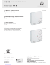
Room temperature controller
for single room control
with LED operating mode indicator
THERMASREG
®
RTR - E 6020
RTR - E 6025
Room temperature controller
for single room control
with LED operating mode indicator,
LC display, and clock
Connecting diagram
RTR - E 6005 ⁄ 6009 ⁄ 6011
Connecting diagram
RTR - E 6020 ⁄ 6025
N
PE
L
F F TA L L1 N N
Heating
Rx
(L)
N
PE
L
F F TA N L1 N L
Heating
Rx
(L)
Type ⁄ WG01 Temperature
Range
Sensor Function
Heating
Item No.
RTR - E 6005 ⁄ 6009 ⁄ 6011 IP 30
RTR-E 6005 +5...+30 °C Room sensor,
Sensor Internal
Room temperature controller 1102-5010-0050-000
RTR-E 6009 +10...+60 °C with remote sensor (L = 4 m) Floor temperature controller 1102-5010-0090-000
RT R-E 6011 +5...+30 °C ⁄
+20...+60 °C
Room sensor,
Sensor Internal,
with remote sensor (L = 4 m)
Room temperature controller and
floor temperature monitor
(combined controller)
1102-5010-0110-000
Features: with night temperature setback, main switch, and LED operating mode indicator
Type ⁄ WG01 Temperature
Range
Sensor Function
Heating
Item No.
RTR - E 6005 ⁄ 6009 ⁄ 6011 IP 30
RTR-E 6020 +5...+30 °C Room sensor,
Sensor Internal
Room temperature controller
with clock
1102-5010-0200-000
RTR-E 6025 +10...+60 °C with remote sensor (L = 4 m) Floor temperature controller
with clock
1102-5010-0250-000
Features: with week programme, main switch, party switch, LC display, and LED operating mode indicator

12
G
Mounting and Installation
Electronic temperature controller with time control – for in-wall installation
Floor temperature controller ..................... 10 ... 60 °C, with wire sensor
Room temperature controller .................... 5 ... 30 °C, with integrated room sensor
TECHNICAL DATA:
Mains voltage: ................................................... 230 V ~ ± 10 %, 50 Hz
Switching current: ..........................................for 6025 ca. 16 A at cos ϕ = 1
Breaking capacity: .........................................3.6 kW
Switching current: ...........................................for 6020 ca. 10 A at cos ϕ = 1
Breaking capacity: .........................................2.3 kW
Switching temperature
difference ............................................................0,7 K
Relay contact: ...................................................“breaks“ when preset temperature is reached
Temperature sensor: ..................................... NTC (according to DIN 44574), length: 4 m
Setting range: ................................................... RTK: 5 to 30 °C (scale 1 to 6), FHK: 10 to 60 °C (scale 1 to 6)
Ambient temperature: ...................................- 10 °C to + 40°C
Connection leads: ............................................ max. 2.5 mm
2
Sensor characteristic: ...................................Temperature ..........................Resistance
10 ............................................... 3.66
20 ............................................... 2.43
30 ............................................... 1.66
40 ............................................... 1.15
50 ............................................... 0.82
Legend for Fig. 2
1. Buttons + ⁄ – Function: Varying setting parameters
2. Slide switch (“party switch“) Function: Change time control programme ⁄ continuous operation
3. LED Function: Heating ON ⁄ OFF
4. Turning knob Function: Temperature setting
5. RESET button Function: Deleting time and day, heating and reduced periods are retained
6. Slide switch Function: Heating ON ⁄ OFF
7. Button “C“ Function: Programme call
NOTE: Factory setting is restored by simultaneously pressing buttons C (item 7), + and – (item 1).
Field of application ⁄ mode of operation
Settings are made differently for working days (e.g. Monday – Friday) and resting days (e.g. Sa, Su). The allocation of working days ⁄ resting days
can be varied, see 16. The slide switch “ON ⁄ OFF“ (see Fig. 2, item 6) separates the heating circuit unipolar from the mains and switches the
device off, except for the clock. The slide switch “time control programme ⁄ continuous“ (see Fig. 2, item 2) allows switching between regulat
-
ing heating with and without time-control (e.g. continuous operation for a party). Pilot control: The temperature controllers have one output
(TA), which is activated during the programmed reduced periods. Therefore, such controllers can be connected as main controller for up to
10 controllers without clock (as satellite controllers) of the types 6009 or 6011. This requires a connection to be made between terminal TA
of the main controller and the respective TA terminals of the satellite controllers. Then, temperature is lowered at each satellite controller
by 5 °C when the main controller switches to reduced temperature.
Instructions regarding Fig. 1
IMPORTANT NOTES - ATTENTION!
Only authorized and qualified electrician personnel may work on 230 V mains.
Respective safety regulations issued by the VDE and the local energy supply companies must be observed when connecting these de vices.
In case of fault, mains voltage might apply at the sensor wire (see Fig. 1).
For regulating hot water heating systems, control valves of the type “currentless closed“ are needed.
Connection leads must be straight with ends ca. 6 mm stripped.
The sensor cable needs to be laid in a separate conduit and must not be laid together with live mains voltage lines.
Mounting & installation – Cut off mains voltage!
Mounting of remote sensor (for type 6025): The remote sensor is laid inside a protective conduit at heating mat level, central between heating
conductors. Mounting of temperature controller: Both controllers are installed in usual in-wall flush boxes of Ø 55 mm (according to DIN
49073, part 1). When using additional intermediate terminals, a deeper flush box should be used.
• Lift off turning knob carefully with a screwdriver.
• Loosen fastening screw and lift off controller cover.
• For connecting, please observe Fig. 1
• Attention! Arrange retainer ring above the wallpaper and mount controller with self-tapping screw to in-wall flush box.
• Thereafter, place frame and cover on the in-wall socket and tighten screws.
• Then put turning knob back on the device (watch correct groove position).
Mounting instructions – room temperature controllers:
• Mounting height: ca. 1.5 m above finished floor
• Avoid outside walls and draft from windows and doors!
• Make sure regular room convection air reaches the controller unobstructed. Therefore, the controller shall not be located inside shelf
units, or behind curtains, or similar covering.
• Foreign heat is of detrimental influence to control accuracy.

13
Instructions regarding Fig. 2
Field of application ⁄ mode of operation
This electronic room temperature controller with time control is used for controlling temperature in single rooms. The device consists of a
control module for presetting the desired temperature, and a temperature sensor measuring that temperature and transmitting it to the
control module. Floor temperature controller 6025: Application e.g. for direct electric floor heating as supplementary heating system for
tempering bathroom floors. Control parameter is the floor temperature, which is measured by a remote sensor at heating mat level. Room
temperature controller 6020: Application in controlling electric storage heating systems, electric direct heating systems (e.g. convectors),
or hot water heating systems with control valves type “currentless closed“. Control parameter is the room temperature, which is measured
by an integrated sensor. A built-in digital clock allows switching from heat period temperature to reduced temperature twice per day, i.e. up
to two different heat and reduced temperature periods can be determined.
Narrowing temperature range
The controller‘s temperature setting range can be mechanically narrowed down by reducing the turning angle of the turn knob. To do so,
proceed as follows:
• Carefully lever off turning knob with a screwdriver (see Fig. 2, item 3).
• Pull out locking pin (range-narrowing at the device cover) using needle-nosed pliers.
• Turn the little gearwheels so to limit turning knob motion.
• To reattach turning knob, proceed in reverse order.
• It is not necessary to cut off mains voltage while narrowing temperature range.
NOTE: Please mind that any type of floor covering must not exceed a certain temperature limit. Get advice from a specialist about maximum
temperature permissible for your flooring and preset that temperature as described above.
Putting in operation: Both controllers are ex works factory-programmed as follows:
– 6:00 h to 21:59 h – heat period, temperature selection by turning knob
– 22:00 h to 5:59 h temperature reduced to 15 °C
– Working days (Monday - Friday)
– Resting days (Saturday - Sunday)
Putting in operation ⁄ setting clock
If you wish to use factory settings, proceed as follows when putting in operation:
• Press button C and
• Set the clock using the +⁄– buttons − the time is shown on the display
• Press again button C and
• Set the weekday using the +⁄– buttons − the weekday is displayed (see also Fig. 3, item f)
After 3 minutes, the controller automatically switches to operating mode. The previously entered values (time and weekday) are taken on.
Thereby, putting in operation is completed and the device is operating.
NOTE: To adapt the controller to your specific individual needs, please proceed as described under chapter “Programming“.
PROGRAMMING
If you wish to use different settings (see also “Putting in operation“), program controllers in the following order (factory settings in
parentheses), reduced temperature (15 °C):
For working days For resting days
Start 1
st
heat period (06:00 h) Start 1
st
heat period (06:00 h)
Start 1
st
reduced period (22:00 h) Start 1
st
reduced period (22:00 h)
Start 2
nd
heat period (00:00 h) Start 2
nd
heat period (00:00 h)
Start 2
nd
reduced period (00:00 h) Start 2
nd
reduced period (00:00 h)
The following steps are necessary for programming each sequence:
• Press button C and
• Set the new values using the +⁄– buttons − the values ⁄ readings in the display are refreshed
• Press button C again to complete programming
NOTE: Programming may be ended at any arbitrary point by pressing button C. After 3 minutes, the controller automatically shows the
“ current“ time of the day and continues to operate with the values entered.
Example for programming
In the following, reduced period temperature, time span of the first heat period for working days, and first reduced period shall be changed.
Settings for resting days shall be retained. For programming, proceed as follows:
• Press button C – the current time of the day is displayed
• Press button C again – the current weekday is displayed
• Press button C again
• Set the reduced period temperature using the +⁄– buttons – the new reduced period temperature, e.g.15 °C, is displayed
• Press button C again – symbol A and the working days are displayed
• Set the 1
st
heat period using the +⁄– buttons – the start of the new 1st heat period, e.g. 7:00 h, is displayed
• Press button C again – symbol A and the working days are displayed
• Set the 1
st
reduced period using the – the start of the new 1st reduced period, e.g. 21:00 h, is displayed
• Press button C again
• Make no further entries – after 3 minutes, the controller starts to operate with the new values

14
Recall factory settings
The easiest way to restore aforesaid factory settings is as follows:
• Simultaneously press buttons C, +, and – (see Fig.2)
• Then update time of the day and weekday (see chapter “Putting in operation“)
OPERATION
Continuous operation: If you want to regulate your heating system without time control, push the left slide switch (see Fig. 2, item. 2) down
to “continuous“ (sun symbol). The clock programme is thereby retained. After switching back to “time control“, the controller continues to
operate according to the predefined heating-time profile.
To turn heating off: If you want to turn off heating intentionally, push the right slide switch (see Fig. 2, item 6) down (circle symbol)
To turn heating on: If you want to turn on heating intentionally, push the right slide switch (see Fig. 2, item 6) up (circle ⁄ dot symbol).
NOTE: The LED only lights up when heat is demanded.
POWER FAILURE
In case of a power failure or interruption or short-circuit of the sensor wire, heating is switched off. The display starts blinking (see Fig. 2).
Time is shown on the display for ca. two more days. The programmed values however are retained. Set time again if necessary (see chapter
“Putting in operation“).
Attention: In case of fault, mains voltage might apply at the sensor wire.
TROUBLE SHOOTING
Diagnose Possible cause ⁄ remedy
Heating doesn‘t work: ............................................................ Apply ⁄ check mains voltage,
check heating system, check sensor wire,
check preset temperature, check reduced-period temperature
Nothing shown on the display ⁄ controller: ...................... Apply ⁄ check mains voltage,
check device, check settings of working ⁄ resting days
Switching to heat ⁄ reduced period too early ⁄ late
: ....... Press RESET, then make new settings
LED blinking: ............................................................................. Sensor not connected or defect
Connection – floor temperature controller
Fig. 1A
Connection – room temperature controller
Fig. 1B
Programming A+R
Device overview (operating elements) Fig. 2
Display elements Fig. 3
Definition of working and resting days
You can change the factory-preset working days (Monday
– Friday) and resting days (Saturday – Sunday) as follows:
• Simultaneously press buttons + and –
• Then press button C
− The symbols of all weekdays appear on the display
− Symbols A and Mo are blinking
• Press button + to make Mo a resting day
− Symbol A disappears and symbol R appears
− Symbol Mo is blinking
• Press button C to activate the next day (Di) and proceed
analogously.
• Simultaneously press buttons + and – to return to
normal controller operation.
Use buttons + and – to switch between R = resting days and
A = working days forth and back.
Confirm each change by pressing button C.
Legend
a. Groups of days:
A = working days, R = resting days
(Saturday and Sunday)
b. 1
st
heat period c. 1
st
reduced period
d. 2
nd
heat period e. 2
nd
reduced period
f. weekdays Monday through Sunday
(from left to right)
F F TA N L1 N L
N PE
L
Heating
TA (optional
Phase L)
F F TA N L1 N L
N PE
L
Heating
NTC
TA (optional
Phase L)
17:00
A
R
a
b
c
d
e
f
Mon Tue Wed Thu Fri Sat Sun

15
G
General notes
Our “General Terms and Conditions for Business“ together with the “General Conditions for the Supply of Products and Services of the Electrical
and Electronics Industry“ (ZVEI conditions) including supplementary clause “Extended Retention of Title“ apply as the exclusive terms and conditions.
In additionIn addition, the following points are to be observed:
–
These instructions must be read before installation and putting in operation and all notes provided therein are to be regarded!
–
Devices must only be connected to safety extra-low voltage and under dead-voltage condition. To avoid damages and errors the device
(e.g. by voltage induction) shielded cables are to be used, laying parallel with current-carrying lines is to be avoided, and EMC directives are to
be observed.
–
This device shall only be used for its intended purpose. Respective safety regulations issued by the VDE, the states, their control authorities,
the TÜV and the local energy supply company must be observed. The purchaser has to adhere to the building and safety regulations and has to
prevent perils of any kind.
–
No warranties or liabilities will be assumed for defects and damages arising from improper use of this device.
–
Consequential damages caused by a fault in this device are excluded from warranty or liability.
–
These devices must be installed by authorised specialists only.
–
The technical data and connecting conditions of the mounting and operating instructions delivered together with the device are exclusively
valid. Deviations from the catalogue representation are not explicitly mentioned and are possible in terms of technical progress and continuous
improvement of our products.
–
In case of any modifications made by the user, all warranty claims are forfeited.
–
This device must not be installed close to heat sources (e.g. radiators) or be exposed to their heat flow. Direct sun irradiation or heat
irradiation by similar sources (powerful lamps, halogen spotlights) must absolutely be avoided.
–
Operating this device close to other devices that do not comply with EMC directives may influence functionality.
–
This device must not be used for monitoring applications, which serve the purpose of protecting persons against hazards or injury,
or as an EMERGENCY STOP switch for systems or machinery, or for any other similar safety-relevant purposes.
–
Dimensions of enclosures or enclosure accessories may show slight tolerances on the specifications provided in these instructions.
–
Modifications of these records are not permitted.
–
In case of a complaint, only complete devices returned in original packing will be accepted.
These instructions must be read before installation and putting in operation and all notes provided therein are to be regarded!

31
THERMASREG
®
RTR -E - UP
D G F r
Irrtümer und technische Änderungen vorbehalten.
Errors and technical changes excepted.
Sous réserve d’erreurs et de modifications techniques.
Возможны ошибки и технические изменения.
© Copyright by
S+S Regeltechnik GmbH
Nachdruck, auch auszugsweise, nur mit Genehmigung von S+S Regeltechnik GmbH gestattet.
Reprints, in part or in total, are only permitted with the approval of S+S Regeltechnik GmbH.
La reproduction des textes même partielle est uniquement autorisée après accord de la société S+S Regeltechnik GmbH.
Перепечатка, в том числе в сокращенном виде, разрешается лишь с согласия S+S Regeltechnik GmbH.
/