Page is loading ...

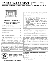
INSTALLING FAN/BLOWER ACCESSORY
MODEL 20UB100B-01
Figure 5
200285-01
Rev. B
2/16
ProCom Heating, Inc.
Bowling Green, KY 42101
www.usaprocom.com
1-866-573-0674
DISCONNECTING WALL MOUNTED HEATER
Wall mounted heater must be disconnected from gas supply and removed
from wall before installing fan accessory. Contact a qualied service person
to do this. Follow all codes.
REMOVING PANEL FROM BACK OF HEATER
Remove panel with a Phillips head screwdriver (see Figure 1).
Panel
Fan/Blower
Assembly
On/Off Switch
Auto/O/Man
Switch
Figure 2
Figure 1
Figure 3
ATTACHING FAN/BLOWER ASSEMBLY
Attach fan/blower to the rear panel of the heater using the four screws pro-
vided (see Figure 2).
FAN OPERATION
To operate in Manual mode, turn on/off switch to the ON position. To operate
in Automatic mode turn AUTO/O/MAN to the desired position, Man position
will remain constantly on. Auto position will be controlled by the sensor on
fan blower unit. To stop the operation, turn unit switch to the O position (see
Figure 3).
GROUNDING INSTRUCTIONS
This fan/blower is for use on 120 volts. The cord has a plug as shown at
A in Figure 4. An adapter as shown at C is available for connecting three-
blade grounding-type plugs to two-slot receptacles. The green grounding
lug extending from the adapter must be connected to a permanent ground
such as a properly grounded outlet box. The adapter should not be used if
a three-slot grounded receptacle is available.
ELECTRICAL CONNECTION
Do not use this fan/blower if any part of it has been
under water. Immediately call a qualied service tech-
nician to inspect the fan/blower and replace any part
of the electrical system which has been under water.
This fan/blower accessory must be grounded. This unit comes with a 3-prong
grounding plug for your protection against electrical shock. Use standard, 3
holes, grounded outlet. If an extension cord is needed it must have a 3 prong
plug and a 3 hole receptacle. An undersized cord will cause a drop in live
voltage and could result in loss of power and overheating.
ELECTRICAL WIRING
Any electrical re-wiring of this appliance must be done by a qualied elec-
trician. This wiring must be done in accordance with local codes and/or in
Canada with the current CSA C22.1 Canadian Electrical Code, and for US
installations, the National Electrical Code ANSI/NFPA NO 70.
WARNING: If repairing or replacing any electrical
component or wiring, the original wire routing, color
coding and securing locations must be followed.
CAUTION: Label all wires prior to disconnection when
servicing controls. Wiring errors can cause improper
and dangerous operation.
WARNING: Never attempt to service fan/blower while
it is plugged in, operating, or hot. Burns and electrical
shock could result. Only a qualied service person
should service or repair fan/blower.
Verify proper operation after servicing. If any of the original wire as supplied
with the appliance must be replaced, it must be replaced with a wire of at
least a 105º C temperature rating.
Grounding Pin
Grounding Means
Metal Screw
Cover of
Grounded
Outlet Box
A
B
C
Adapter
Figure 4
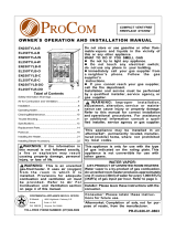
Figure 5
Motor
Black
Green
White
Switch
Thermostat Switch
AUTO
O
MAN
FAN OPERATION
To operate the manual unit, turn ON/OFF switch to the ON position. To op-
erate the Automatic unit, turn AUTO/O/MAN switch to the desired position.
MAN position will remain constantly on. AUTO position will be controlled by
the sensor on the fan blower unit. The sensor will be activated when the
temperature of the sensor head reaches the set point of the switch after the
heater is started. To stop the operation, turn the switch to the O position.
MAN O AUTO
/