Page is loading ...

Questions, problems, missing parts? Before returning to your retailer, call
our customer service department at 1-866-573-0674, 7:30 am - 4:15 pm CST,
Monday through Friday or email [email protected]
QEB100 BLOWER ACCESSORY
INSTALLATION INSTRUCTIONS
WARNING: ELECTRICAL GROUNDING INSTRUCTIONS This
appliance is equipped with a three-prong (grounding) plug for your
protection against shock hazard and should be plugged directly into
a properly grounded three-prong receptacle.
Spanish/Español
Page 17

www.usaprocom.com
200070-01E2
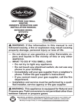
Parts included with this kit
Item Part No. Description Qty
A XB001-01 Power Cord 1
B XB002-01Q Blower 1
C XB003-01 Temperature Sensor 1
D XB004-01Q Connect Wire 1
E PF06-0400-A Rocker Switch 1
PACKAGE CONTENTS
A
B
C
AA
BB
D
E
If any of these pieces are missing or damaged, contact the dealer where you purchased this
kit or ProCom Heating, Inc. at 1-866-573-0674 for referral information.
CC
Hardware
Item Part No. Description Qty
AA GB/T 845-4.2*9.5F M4.2x9.5 Screw 6
BB VL057-01 Cable Tie 2
CC GB/T 845-4.2*9.5 M4.2x9.5 Screw 4

www.usaprocom.com
3200070-01E
SAFETY
IMPORTANT: Read all instruc-
tions and warnings carefully
before starting installation. Fail-
ure to follow these instructions
may result in a possible electric
shock, re hazard and will void
the warranty.
• Read all instructions before using this ap-
pliance.
• If possible always unplug this appliance
when not in use.
• Do not operate any heater with a damaged
cord or plug or after the appliance malfunc-
tions, has been dropped or damaged in any
manner.
• Any repairs to this appliance should be
carried out by a qualied service person.
• Under no circumstances should this ap-
pliance be modied. Parts having to be
removed for servicing must be replaced
prior to operating this appliance again.
• Do not use outdoors.
• Never locate this appliance where it may
fall into a bathtub or other water container.
• Do not run cord under carpeting. Do not
cover cord with throw rugs, runners or the
like. Arrange cord away from trafc areas
and where it will not be tripped over.
• To disconnect this appliance, turn controls
to the off position, then remove plug from
outlet.
• Connect to properly grounded outlets only.
• This appliance, when installed must be
electrically grounded in accordance with
local codes, with the current CSA C22.1
Canadian Electrical Codes or for USA
installations, follow local codes and the
National Electric Code, ANSI/NFPA No. 70.
• Do not insert or allow foreign objects to
enter any ventilation or exhaust opening
as this may cause an electric shock, re
or damage the appliance.
• To prevent possible re, do not block air
intakes or exhaust in any manner.
• Use this appliance only as described in this
manual. Any other use not recommended
by the manufacturer may cause re, electric
shock or injury to persons.
• Avoid the use of an extension cord because
of the risk of overheating the cord and the
risk of re. Extension cords are for tempo-
rary use only. If an extension cord must be
used, it must be UL/CSA certied, rated
at 10A (1250W), 125V maximum with 16
AWG minimum and constructed of two
current carrying conductors with ground. A
heavy duty extension cord with the shortest
length possible for the connection is recom-
mended and must not be longer than 50 ft.
(15.2 m). Do not coil or cover the extension
cord.

www.usaprocom.com
200070-01E4
PREPARATION
Tools Required
• Phillips Screwdriver
• Wire Cutter
This blower contains assembly instructions for ED series.
For the CRHQD250T, CRHSD25RT, BD23 series, Q stove, PCSD25RT series and FBD400
series see page 8 - 13.
BLOWER INSTALLATION ED SERIES
Install
Rocker
Switch
Install
Blower
Top Cover
Install Power
Cord and
Grounding
Terminal
Protection Tab
Install Temperature
Sensor to Back
of Firebox after
Removing Top Cover

www.usaprocom.com
5200070-01E
AA
WARNING: Before installing
the blower, be certain to turn off
the unit, and allow time for unit
to cool down.
1. Unscrew and remove top cover of the
replace (see Figure 1).
Figure 1 - Remove Fireplace Top Cover
Figure 2 - Installing Power Cord
Figure 3 - Attaching Blower to Top Cover
2. Attach the power cord to the replace top
cover with 3) M4.2X8 screws (AA) (see
Figure 2).
3. Attach the blower assembly to the top
cover with 4) M4.2X8 screws (CC) (see
Figure 3).
AA
CC
INSTALLATION - ED SERIES
Figure 4 - Installing Grounding Terminal
to Top Cover
4. Attach the grounding terminal to top cover
with 1) M4.2X8 screw (AA). Refer to wiring
diagram, page 15. Be sure to insert the
gasket between the protection tab and
the grounding terminal (see Figure 4).
Figure 5 - Connecting Blower Wire to
Wire Connector
5. Insert the blower connector (male port)
into the female port on the wire connector.
This protects the jacket in the replace
(see Figure 5).
Grounding
Terminal
Gasket
Protection Tab
Male Port
Female
Port

www.usaprocom.com
200070-01E6
T1
T2
Figure 9 - Installing Temperature Sensor
Figure 10 - Feeding Wire Harness
Figure 11 - Temperature Sensor Wires
9. Attach temperature sensor to the back of
the rebox with 2) M4.2X8 screws (AA)
(see Figure 9).
10. Insert the wires marked with AUTO, OFF
and MAN into wire slot in the right corner.
Feed them as close to the bottom of the
rebox as possible (see Figure 10).
MAN
OFF
AUTO
11. Connect two black and yellow wires (fe-
male ports) marked T1 and T2 with the
two male ports on the temperature sensor
(see Figure 11).
INSTALLATION - ED SERIES
Figure 7 - Connecting P2 Wires
Figure 6 - Connecting P1 Wires
Figure 8 - Securing Blower Wires
P2
6. Insert the female port, which is on the
white power supply wire (marked with P1),
into the corresponding male port (marked
with P1), (see Figure 6).
7. Insert the male port, which is on the black
power supply wire (marked with P2), into
the corresponding female port (marked
with P2), (see Figure 7).
P1
8. Bundle the wiring with the cable tie (BB).
Attach cable tie to the top panel through
the hole as shown in Figure 8. This is to
avoid any heat damage to the insulation
board.
BB
Temperature
Sensor
Install End of Cable
Tie Through Hole
AA
Temperature
Sensor

www.usaprocom.com
7200070-01E
Figure 12 - Removing Grill from Fireplace
Figure 13 - Removing Screws from
Control Panel
Figure 14 - Inserting Rocker Switch Wires
12.
Remove 2 screws securing grill to stove
front. Carefully set grill aside (see Fig-
ure 12).
AUTO
OFF (O)
MAN
Rocker Switch
Figure 15 - Connecting Wires to Rocker
Switch
Figure 16 - Installing Rocker Switch
Figure 17 - Protection Tab on Top Cover
13. Remove logs and carefully set aside. Note
log placement before removing.
14. Remove 2 screws securing control panel.
Pull the control panel out without discon-
necting the ignitor wire (see Figure 13).
IGNITOR
15. Feed the AUTO, OFF, MAN connectors
through the rocker switch hole on the left
side of the control panel (see Figure 14).
16. Connect the AUTO, OFF, MAN wires to
the three corresponding male tabs on the
rocker switch (see Figure 15).
INSTALLATION - ED SERIES
17. Push the rocker switch into the control
panel (see Figure 16).
18. Reattach the control panel with two screws
removed in step 14 (see Figure 13).
19. Reinstall logs according to original layout.
Refer to owner's manual for log place-
ment.
20. Install grill with 2 screws removed previ-
ously (see Figure 12).
21. Replace top cover (see Figure 1, page 5).
22. Push the protection tab to embed it into
the surface of the top cover (see Figure
17).

www.usaprocom.com
200070-01E8
CRHQD250T and Q Series
INSTALLATION
Install Rocker Switch
Install
Rocker
Switch
Install Rocker Switch Install Rocker Switch
Install Blower
Install Blower
Install
Blower
Install Wiring and
Grounding Terminal
Install
Wiring and
Grounding
Terminal
Install
Wiring and
Grounding
Terminal
Install Temperature
Sensor
Install Temperature
Sensor
BD23 Series
PCSD25RT and CRHSD25RT
FBD400 Series
Install Temperature
Sensor

www.usaprocom.com
9200070-01E
AA
AA
CC
INSTALLATION - CRHQD250T, Q SERIES, B23 SERIES,
PCSD25RT, CRHSD25RT AND FBD400 SERIES
WARNING: Before installing
the blower, be certain to turn off
the unit, and allow time for unit
to cool down.
1. Remove screws securing blower access
panel to back of stove (see Figure 18).
Place screws in a safe location.
Blower
Temperature
Sensor
Power Cord
Figure 18 - Removing Blower Access Panel
Figure 19 - Attaching Blower to Blower
Access Panel
Figure 20 - Attaching Power Cord to
Blower Access Panel
Figure 21 - Attaching Temperature
Sensor to Firebox
Figure 22 - Feeding Wire Harness
2. Attach blower to the inside of the blower
access panel with 4) M4.2X8 screws (CC)
(see Figure 19).
3. Attach the power cord to the outside of
the blower access panel with 3) M4.2X8
screws (AA) (see Figure 20).
4. Attach the temperature sensor to the back
of the rebox with 2) M4.2X8 screws (AA)
(see Figure 21).
5. Insert wires marked with AUTO, OFF and
MAN into wire slot in the right corner of
the stove body. Feed the wires down and
as close to the bottom of the stove as
possible (see Figure 22).
PCSD25RT Only

www.usaprocom.com
200070-01E10
AA
INSTALLATION - CRHQD250T, Q SERIES, B23 SERIES,
PCSD25RT, CRHSD25RT AND FBD400 SERIES
6. Connect two black and yellow wires (fe-
male ports) marked T1 and T2 with the
two male ports on the temperature sensor
(see Figure 23).
Figure 23 - Temperature Sensor Wires
T1
T2
Temperature
Sensor
Grounding
Tab
Grounding
Tab
7. Insert the female port, which is on the
white power supply wire (marked with P1),
into the corresponding male port (marked
with P1) (see Figure 24).
Figure 25 - Connecting P2 Wires
Figure 24 - Connecting P1 Wires
P2
P1
8. Insert the male port, which is on the black
power supply wire (marked with P2), into
the corresponding female port (marked
with P2) (see Figure 25).
9. Insert the blower connector (male port)
into the female port on the wire connector.
This protects the jacket in the replace
(see Figure 26).
Figure 26 - Connecting Blower Wire to
Wire Connector
Figure 27 - Attach Grounding Wire
Figure 28 - Adjusting Grounding Tab
10. Attach the grounding terminal to the tab
on the right side of the blower access hole
with 1) M4.2X8 screw (AA) (see Figure
27).
11. Push grounding tab inwards (approxi-
mately 60 degrees) (see Figure 28).
Male Port
Female
Port

www.usaprocom.com
11200070-01E
BD23 Series
PCSD25RT Shown
INSTALLATION - CRHQD250T, Q SERIES, B23 SERIES,
PCSD25RT, CRHSD25RT AND FBD400 SERIES
Cable Tie
Cable
Tie
Fixed
Hole
Fixed
Hole
Figure 29 - Securing Blower Wires
Figure 30 - CRHQD250T and Q Series
Removing Grill
12. Bundle the wiring with the cable tie (see
Figure 29). Attach cable tie to the stove
through the hole as shown in Figure 29.
This is to avoid any heat damage. Actual
heater may vary from illustration. BD23
Series models have the cable tie hole in
the top panel. For all other models, the
hole will be to the right of the blower ac-
cess opening.
13. CRHQD250T and Q Series Remove 2
screws securing grill to stove front. Care-
fully set grill aside (see Figure 30).
CRHSD25RT and PCSD25RT Rotate
handle and open the door.
14. Remove logs and carefully set aside. Note
log placement before removing.

www.usaprocom.com
200070-01E12
INSTALLATION - CRHQD250T, Q SERIES, B23 SERIES,
PCSD25RT, CRHSD25RT AND FBD400 SERIES
15. CRHQD250T, Q Series and BD32 Series
Remove screws securing front log bracket
and control panel (see Figure 31a).
CRHSD25RT and PCSD25RT Remove
screws securing control panel (see Figure
31b).
FBD400 Series Remove screws securing
control panel (see Figure 31c).
Figure 31a - CRHQD250T, Q Series and
BD32 Series Log Bracket and Control Panel
Figure 32 - BD23 Series, Control Panel
Door
Figure 31b - CRHSD25RT and PCSD25RT
Control Panel
Figure 31c - FBD400 Series Control
Panel
16. BD23 Series Remove screws securing
control panel door (see Figure 32).
17. Feed the AUTO, OFF, MAN connectors
through the rocker switch hole on the left
side of the control panel (see Figure 33).
Figure 33 - Inserting Rocker Switch
Wires (Hole Location Varies by Model)
AUTO
OFF (O)
MAN
Rocker Switch
Figure 34 - Connecting Wires to Rocker
Switch
IGNITOR
18. Connect the AUTO, OFF, MAN wires to
the three corresponding male tabs on the
rocker switch (see Figure 34).

www.usaprocom.com
13200070-01E
INSTALLATION - CRHQD250T, Q SERIES, B23 SERIES,
PCSD25RT, CRHSD25RT AND FBD400 SERIES
19. Push the rocker switch into the control
panel (see Figure 35).
Figure 35 - Installing Rocker Switch
20. Reattach the control panel and log bracket
(if applicable) with screws removed in step
15 (see Figure 31, page 12).
21. Reinstall logs according to original layout.
Refer to owner's manual for log place-
ment.
22. CRHQD250T and Q Series Replace grill
with 2 screws removed previously (see
Figure 30, page 11).
For other models, close stove door.
23. Check all wires, then replace blower ac-
cess panel (see Figure 18, page 9).
ELECTRICAL CONNECTION
A 15 amp, 120 Volt, 60 Hz circuit with a
properly grounded outlet is required. The
replace should be on a dedicated circuit.
Other appliances on the same circuit may
cause the circuit breaker to trip, or the fuse to
blow when the heater is in operation. Plan the
installation to avoid the use of an extension
cord. Extension cords are for temporary use
only. If an extension cord must be used, it must
be UL/CSA certied, rated at 10A (1250W),
125V maximum with 16 AWG minimum and
constructed of two current carrying conductors
with ground. A heavy duty extension cord with
the shortest length possible for the connec-
tion is recommended and must not be longer
than 50 ft. (15.2 m). Do not coil or cover the
extension cord.
WARNING: Electrical outlet
wiring must comply with local
building codes and other appli-
cable regulations to reduce the
risk of re, electrical shock and
injury to persons.
WARNING: Do not use this
replace if any part of it has been
under water. Immediately call a
qualied service technician to
inspect the replace and replace
any part of the electrical system
which has been under water.

www.usaprocom.com
200070-01E14
GROUNDING INSTRUCTIONS
This heater is for use on 120 volts. The
cord has a plug as shown at A. An adapter
as shown at C is available for connecting
three-blade grounding-type plugs to two-slot
receptacles. The green grounding lug ex-
tending from the adapter must be connected
to a permanent ground such as a properly
grounded outlet box. The adapter should not
be used if a three-slot grounded receptacle
is available.
Grounding Pin
Grounding Means
Metal Screw
Cover of
Grounded
Outlet Box
A
B
C
Adapter
OPERATION
Using rocker switch, turn blower on and
check for operation. Turn on rocker switch to
the desired position. In the MAN position the
blower will remain constantly on. In the AUTO
position the blower will be controlled by the
temperature sensor. To stop the operation turn
rocker switch to the O position.
CARE AND MAINTENANCE
Always disconnect the appliance
from the main power supply and
allow it to cool before any servic-
ing operation.
The motors used on the fan heater and ame
blower are pre-lubricated for extended bearing
life and require no further lubrication.
Periodic cleaning/vacuuming of the appliance
around the air intake and exhaust, as well as
the fan heater is recommended. For heavy
or continuous use, periodic cleaning must
be done more frequently. If the heater blows
alternating cold and warm air, check the fan
for free movement and for debris restricting
air ow. If the fan does not move freely, the
unit must be turned off and the fan replaced
immediately in order to prevent further dam-
age to the unit.

www.usaprocom.com
15200070-01E
ELECTRICAL WIRING DIAGRAM
Any electrical re-wiring of this appliance must
be done by a qualied electrician. This wiring
must be done in accordance with local codes
and/or in Canada with the current CSA C22.1
Canadian Electrical Code, and for US instal-
lations, the National Electrical Code ANSI/
NFPA NO 70.
WARNING: If repairing or
replacing any electrical compo-
nent or wiring, the original wire
routing, color coding and secur-
ing locations must be followed.
Note: Use only original replacement parts. This will protect your warranty coverage for parts
replaced under warranty.
PARTS UNDER WARRANTY
Contact authorized dealers of this product. If they can’t supply original replacement parts, call
Customer Service toll free at 1-866-573-0674 for referral information.
When calling Customer Service or your dealer, have ready:
• Your name
• Your address
• Model and serial number of your heater
• How heater was malfunctioning
• Type of gas used (Propane/LP or Natural gas/NG)
• Purchase date
Usually, we will ask you to return the defective part to the factory
PARTS NOT UNDER WARRANTY
Contact authorized dealers of this product. If they can’t supply original replacement part(s)
call Customer Service toll free at 1-866-573-0674 for referral information.
When calling Customer Service have ready:
• Model number of your heater
• The replacement part number
REPLACEMENT PARTS
Blower
BLACK
WHITE
GREEN
BLACK
RED
~120V
60Hz
Bushing
Strain Relief
Power
Cord
Rocker Switch
Temperature Sensor
AUTO OFF MAN

200070-01
Rev. E
01/16
REGISTER YOUR PRODUCT AT WWW.USAPROCOM.COM
IMPORTANT: We urge you to register your product within 10 days of date of installation, complete
with entire serial number which can be found on the rating plate. Please ll out the warranty infor-
mation above for your personal records. Retain this manual for future reference.
Always specify model and serial numbers when communicating with customer service.
We reserve the right to amend these specications at any time without notice. The only warranty applicable
is our standard written warranty. We make no other warranty, expressed or implied.
LIMITED WARRANTY
ProCom Heating, Inc. warrants this product to be free from defects in materials and components for ONE
(1) year from the date of rst purchase, provided that the product has been properly installed by a qualied
installer in accordance with all local codes and instructions furnished with the unit, operated and main-
tained in accordance with all applicable instructions. To make a claim under this warranty, the Bill of Sale
or cancelled check must be presented.
RESPONSIBILITY OF OWNER
This warranty is extended only to the original retail purchaser. This warranty covers the cost of part(s)
required to restore this heater to proper operating condition. Warranty part(s) MUST be obtained through
ProCom Heating, Inc. who will provide original factory replacement parts. Failure to use original factory
replacement parts voids this warranty. The heater MUST be installed by a qualied installer in accordance
with all local codes and instructions furnished with the unit.
WHAT IS NOT COVERED
This warranty does not apply to parts that are not in original condition because of normal wear and tear or
parts that fail or become damaged as a result of misuse, accidents, lack of proper maintenance or defects
caused by improper installation. Travel, diagnostic cost, labor, transportation and any and all such other
costs related to repairing a defective heater will be the responsibility of the owner.
TO THE FULL EXTENT ALLOWED BY THE LAW OF THE JURISDICTION THAT GOVERNS THE SALE
OF THE PRODUCT, THIS EXPRESS WARRANTY EXCLUDES ANY AND ALL OTHER EXPRESSED
WARRANTIES AND LIMITS THE DURATION OF ANY AND ALL IMPLIED WARRANTIES. INCLUDING
WARRANTIES OF MERCHANTABILITY AND FITNESS FOR A PARTICULAR PURPOSE TO ONE (1)
YEAR ON ALL COMPONENTS FROM THE DATE OF FIRST PURCHASE. PROCOM HEATING, INC.'S
LIABILITY IS HEREBY LIMITED TO THE PURCHASE PRICE OF THE PRODUCT AND PROCOM HEAT-
ING, INC. SHALL NOT BE LIABLE FOR ANY OTHER DAMAGES WHATSOEVER INCLUDING INDIRECT.
INCIDENTAL OR CONSEQUENTIAL DAMAGES.
Some states do not allow a limitation on how long an implied warranty lasts or an exclusion or limitation of
accidental or consequential damages, the above limitation on implied warranties, or exclusion or limitation
on damages may not apply to you.
This warranty gives you specic legal right, and you may also have other rights that vary from state to state.
WARRANTY
KEEP THIS WARRANTY
Model _______________________________
Serial No. ____________________________
Date Purchased _______________________
Keep receipt for warranty verication.
ProCom Heating, Inc.
Bowling Green, KY 42101
www.usaprocom.com
1-866-573-0674

¿Preguntas, problemas, piezas faltantes? Antes de volver a la tienda, llame a
nuestro Departamento de Servicio al Cliente al 1-866-573-0674, de lunes a viernes de
7:30 a.m. a 4:15 p.m., Hora del Centro, o envíe un correo electrónico a
customerser[email protected].
QEB100 ACCESORIO SOPLADOR
INSTRUCCIONES DE INSTALACIÓN
ADVERTENCIA: INSTRUCCIONES PARA LA CONEXIÓN ELÉC-
TRICA A TIERRA Este aparato está equipado con un enchufe de tres
clavijas (con conexión a tierra) para protegerlo contra el riesgo de
descargas eléctricas y debe ser enchufado directamente a un toma-
corriente de tres patas con conexión a tierra receptáculo.

www.usaprocom.com
200070-01E18
Piezas incluidas con este equipo
Art. Pieza # Descripción Cant.
A XB001-01 Cable de alimentación 1
B XB002-01Q Soplador 1
C XB003-01 Sensor de temperatura 1
D XB004-01Q Cables conectores 1
E PF06-0400-A Interruptor oscilante 1
CONTENIDO DEL PAQUETE
A
B
C
AA
BB
D
E
Si alguna de estas piezas falta o está dañado, póngase en contacto con el distribuidor donde ad-
quirió el kit o ProCom Calefacción, Inc. al 1-866-573-0674 para obtener información de referencia.
CC
Hardware
Art. Pieza # Descripción Cant.
AA GB/T 845-4.2*9.5F M4.2x9.5 Tornillo 6
BB VL057-01 Amarre de cable 2
CC GB/T 845-4.2*9.5 M4.2x9.5 Tornillo 4

www.usaprocom.com
19200070-01E
SEGURIDAD
IMPORTANTE: Lea con atención
todas las instrucciones y ad-
vertencias antes de comenzar
la instalación. Si no se siguen
las instrucciones, se puede
provocar una descarga eléctri-
ca o riesgo de incendio, lo que
anulará la garantía.
• Lea todas las instrucciones antes de usar
este electrodoméstico.
• Si es posible, siempre desenchufe este
electrodoméstico cuando no lo use.
• No opere ningún calentador con un cable
o enchufe dañados, o después de fallas
del mismo, de que se haya dejado caer o
dañado de cualquier forma.
• Toda reparación de este electrodoméstico
debe realizarla un técnico calicado.
• Bajo ninguna circunstancia se debe mo-
dicar este electrodoméstico. Las piezas
que se deben retirar para reparación se
deben reemplazar antes de volver a hacer
funcionar este electrodoméstico.
• No lo use en exteriores.
• Nunca coloque este calentador donde se
pueda caer dentro de una bañera u otro
contenedor de agua.
• No coloque el cable debajo de una al-
fombra. No cubra el cable con alfombras,
tapetes o similares. Coloque el cable lejos
de zonas de tránsito en donde nadie se
pueda tropezar y caer.
• Para desconectar este electrodoméstico,
gire los controles a la posición de apagado
y luego retire el enchufe del tomacorriente.
• Conecte sólo a tomacorrientes con la de-
bida puesta a tierra.
• Cuando está instalado, este electrodomés-
tico debe presentar una puesta eléctrica a
tierra conforme a los códigos locales, a los
Códigos de Electricidad de Canadá CSA
C22.1 o, para instalaciones en EE.UU.,
seguir los códigos locales y el Código
Nacional de Electricidad, ANSI/NFPA No.
70.
• No introduzca objetos extraños ni permita
que entren en las aberturas de escape o
ventilación, ya que pueden provocar des-
cargas eléctricas, incendios o daños en el
electrodoméstico.
• Para evitar incendios, no bloquee las entra-
das ni salidas de aire de ninguna manera.
• Utilice este electrodoméstico sólo como se
describe en este manual. Cualquier otro
uso no recomendado por el fabricante pue-
de causar incendios, descargas eléctricas
o lesiones personales.
• Evite utilizar extensiones eléctricas para
evitar riesgos de sobrecalentamiento y de
incendio. Las extensiones eléctricas son
sólo para uso temporal. De ser necesaria
una extensión eléctrica, ésta debe estar
certicada UL/CSA, clasicada como 10
A (1250 W), 125 V como máximo con 16
AWG como mínimo y fabricada con dos
conductores de corriente con puesta a tie-
rra. Se recomienda una extensión eléctrica
para trabajo pesado de la menor longitud
posible para la conexión, que no sobrepase
los 15,24 m (50 pies). No enrolle ni cubra
la extensión eléctrica.

www.usaprocom.com
200070-01E20
PREPARACIÓN
Herramientas necesarias
• Phillips destornillador
• Cortador de alambre
Este soplador contiene instrucciones de montaje para la serie ED.
Para el CRHQD250T, CRHSD25RT, series BD23, estufa Q, series PCSD25RT y FBD400
series consulte la página 24-29 .
INSTALACIÓN DEL VENTILADOR SERIE ED
Instale el
interruptor
oscilante
Instale el
soplador
Cubierta
superior
Instale el cable
de alimentación
y el puerto de
conexión a tierra
Ficha Protección
Instale el sensor
de temperatura
de la cámara de
combustión para
volver después de
quitar la cubierta
superior
/