Page is loading ...

PLEASE LEAVE THIS MANUAL WITH THE DEHUMIDIFIER OWNER
INSTALLED BY: INSTALLER PHONE: DATE INSTALLED:
1 English
Model E080 & E100
Dehumidifi er
INSTALLATION AND OWNER’S MANUAL
Product Info &
Digital Manual

2 English
Table of Contents
Safety Instructions........................................3
Whole Home Dehumidification..........................3
Operating the Dehumidifier..............................3
Energy Savings Tips ....................................4
Maintenance ..............................................4
Cleaning the Filter......................................4
Cleaning the Drain .....................................5
Specifications .............................................6
Preparing the Unit for Installation.......................6
Repositioning the Control for the Application .......7
Moving the Control.................................7
Installing the Duct Collars ..............................7
Installing the Dehumidifier...............................8
Dehumidifier Location .................................8
Leveling and Raising the Dehumidifier...............8
Installing a Condensate Pan Under the
Dehumidifier . . . . . . . . . . . . . . . . . . . . . . . . . . . . . . . . . . . . . . . . . . . . 8
Installing the Drain . . . . . . . . . . . . . . . . . . . . . . . . . . . . . . . . . . . . . 9
Installing Ductwork .......................................9
Ducting the Dehumidifier Inlet and Outlet to the
HVAC System ...........................................10
Ducting the Dehumidifier Outlet to the HVAC
System with Dedicated Dehumidifier Inlet
Register...................................................11
Wiring ......................................................11
Wiring to the HVAC System ...........................12
Optional W & Y Wiring.............................12
Wiring to External or Remote Controls...............12
Wiring to a Float Switch ...............................12
Ventilation ................................................ 13
Zoning the Dehumidifier ................................14
Required Components ................................14
Installer Setup . . . . . . . . . . . . . . . . . . . . . . . . . . . . . . . . . . . . . . . . . . . . 15
Setting Up Remote Control – Crawl Space/
Sealed Attic .............................................16
Setting Up Ventilation..................................16
Setting Up Zoning ......................................16
Setting Up External Control............................16
Allowing DEH W/AC.....................................16
Applying an RH Offset..................................17
Starting Up the Unit and Sequence of Operation ......17
Using the Dehumidifier Control Only.................17
Using a Model 76 as a Remote Control..............17
Using an External Control .............................17
Two-Zone Operation...................................17
Troubleshooting..........................................18
Diagnostic Codes ......................................18
Service Parts..............................................22
Limited Warranty ........................................23
Warranty Registration ................................23

3 English
SAFETY INSTRUCTIONS
Be sure to read and understand all safety precautions
and instructions before installing and operating the unit.
!
WARNING
The following precautions indicate a hazardous
situation that, if not avoided,
could
result in death or
serious injury.
• Always disconnect electrical power before starting
installation or servicing to avoid electric shock.
• Always wear glasses/goggles and gloves when
installing the unit. Sharp edges may cause serious
cuts. Use care when cutting plenum openings and
handling ductwork.
• Be sure to use caution when handling the unit.
Dropping the unit may cause personal injury or
equipment damage.
!
CAUTION
The following precautions indicate a hazardous
situation that, if not avoided,
could
result in minor or
moderate injury.
• Be sure the installation, service and maintenance
are performed by a qualied service technician.
Improper installation may cause injury or property
damage.
• This unit is not intended for use by persons
(including children) with reduced physical, sensory
or mental capabilities, or lack of experience
and knowledge, unless they have been given
supervision or instruction concerning use of the unit
by a person responsible for their safety.
• Be sure to supervise children to ensure that they do
not play with the unit.
• Be sure to replace a damaged supply cord. It must
be replaced by a special cord or assembly available
from the manufacturer or its service agent.
NOTICE
The following statements indicate a situation which
can cause damage to the equipment and personal
property, or cause the equipment to operate improperly.
• Do not use in pool applications. Pool chemicals can
damage the dehumidier.
• Do not use solvents or cleaners on or near the
circuit board. Chemicals can damage circuit board
components.
• Wait 24 hours before running the unit if it was not
shipped or stored in the upright position.
• Do not use dehumidication to prevent window
condensation in the winter. To address window
condensation, use ventilation to lower indoor humidity
in the winter.
WHOLE HOME DEHUMIDIFICATION
The AprilAire® Dehumidifier controls the humidity
level in your entire home. A powerful blower inside
the dehumidifier draws air into the cabinet where it
is filtered before having moisture removed. A sealed
refrigeration system removes moisture by moving
the air through a series of tubes and fins that are
kept colder than the dew point of the incoming air.
The dew point is the temperature at which moisture
in the air will condense, much like what occurs on
the outside of a cold glass on a hot summer day. The
condensed moisture drips into the dehumidifier drain
pan to a drain tube routed to the nearest floor drain or
condensate pump. After the moisture is removed, the
air moves through a second coil where it is reheated
before being sent back into the home. The air leaving
the dehumidifier will be warmer and drier than the air
entering the dehumidifier.
You can reduce the amount of humidity that enters the
home by closing windows, doors and fireplace flues
when outdoor humidity is high, and by drying clothes
outside. Direct exhaust from kitchen vents and bath fans
is the best means of controlling humidity due to cooking
and showers/baths. The dehumidifier is not designed to
prevent window condensation in winter. Use ventilation
to lower indoor humidity levels in the winter.
OPERATING THE DEHUMIDIFIER
1. Use the ON/OFF Power Switch, located by the power
cord, to apply power to the dehumidifier.
OTE: NThe ON/OFF Power Switch should stay ON unless the
unit will not be used for an extended period. Use the ON/
OFF Button on the control panel to turn the unit off for short
durations. With the ON/OFF Button in the ON position and
the dehumidifier idle (neither the fan nor the compressor
running) the unit will use less than 3W of power.
1
2
3
4
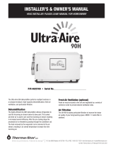
Figure 1: Exterior Components of the Dehumidifier
1 - Control Panel
2 - ON/OFF Power Switch
3 - Filter Access Door
Retaining Screw
4 - Filter Access Door

4 English
2. Use the ON/OFF Button
(see Figure 2)
on the control
panel to turn the dehumidifier ON. The first press
of a button will turn on the display light, so if
the display was dark, you might need to press it
again. Once ON, the display will show the current
dehumidifier setting.
Figure 2: Turning Dehumidifier On
3. The dehumidifier blower will turn on, the word
SETTING disappears from the display, and the words
AIR SAMPLING appear
(see Figure 3)
. This wording
indicates that the dehumidifier is sampling the air to
determine if dehumidification is needed and shows
the measured humidity level.
If the control is already ON, lowering the setting will
initiate air sampling.
AIR SAMPLING
Figure 3: Air Sampling
4. If the Relative Humidity (RH) is above the setting, the
compressor turns on to dehumidify the space. The
word DEHUMIDIFYING appears when the compressor
is turned on
(see Figure 4)
.
Figure 4: Dehumidifying
ENERGY SAVINGS TIPS
ENERGY SAVINGS TIP #1:
Adjust the humidity setting to be as high as is
comfortable to reduce dehumidifier run time. If it feels
clammy or “smells musty,” lower the humidity setting. To
save energy, turn the dehumidifier to OFF when you open
your windows, just as you would with air conditioning.
ENERGY SAVINGS TIP #2:
If vacating your home for an extended period in the
summer, set the RH at 55% and set your thermostat as
high as you are comfortable setting it to in the cooling
mode. This will keep the humidity at a controlled level
while minimizing the amount of cooling energy used.
MAINTENANCE
CLEANING THE FILTER
After initial installation the air filter and drain should be
checked and cleaned every 6 months.
1. Press the ON/OFF Button on the control panel to turn
the unit OFF.
2. Loosen the retaining screw on the filter access door
(see Figure 1)
from the drain side of the dehumidifier
until it releases and then remove the filter door.
3. Slide the filter out of the dehumidifier.
4. Rinse the filter with water to remove dust and
collected particles from the filter.
5. Shake off excess water from the filter.
6. Clean the drain as described in
Cleaning the Drain
on page 5
.
7. Reinstall the filter. An arrow on the filter frame
shows the direction of airflow and it should point
into the dehumidifier.
8. If the filter does not slide back in, make sure the drain
insert has been properly installed.
See Installing the
Drain on page 9.
9. Replace the filter access door and tighten the
retaining screw.
10. Press the ON/OFF Button to turn the dehumidifier
back ON.
The CLEAN FILTER service reminder
(see Figure 5)
will
display on the control every 6 months. To clear
the service message, press the p and q buttons
simultaneously for 3 seconds.
Figure 5: Clean Filter Service Reminder

5 English
CLEANING THE DRAIN
1. With the filter door on the drain side of the
dehumidifier removed, reach in and pull out the
drain insert using the finger loop
(see Figure 6)
.
1
90-2607
Figure 6: Drain Cleaning
1 - Drain Insert
2. Clean the drain pan and drain insert using a mild
detergent.
3. If the drain has a capped tee or elbow to allow
cleaner to be poured directly in the drain, remove
the cap and pour approximately one cup of
vinegar into the tube
(see Figure 7)
. If there is no
visible access to the drain line from outside of
the dehumidifier, pour approximately one cup of
vinegar into the drain pan of the dehumidifier where
the drain insert was located.
4. Reinstall the drain insert by gently placing the
tip into the drain opening and rocking the insert
downwards into place. When inserted properly, the
top of the drain insert will be at the same height as
the filter guide channel.
5. If the dehumidifier has clear flexible drain tubing,
look for excess buildup in the drain line that might
prevent water flow, and replace as needed. Clear,
smooth, flexible 3/4" inner diameter (ID) drain tubing
is available in most hardware stores or Do-It-
Yourself (DIY) retail stores.
NOTICE
Running the dehumidier without the drain insert can
lead to condensate leaks.
OTE: N Drain insert must be installed before operationg.
2
1
90-2693
Figure 7: Capped Drain Access for Cleaning Process
1 - Cap 2 - Condensate
Drain Line

6 English
SPECIFICATIONS
Model E080 Model E100
Unit Weight 63 lbs. 64 lbs.
Capacity
80°F, 60% RH Conditions 80 pints per day @ 185 CFM 100 pints per day @ 280 CFM
Power
115 VAC, Single Phase, 60 Hz 5.1A operating current 6.9A operating current
Dehumidifier Inlet Air Conditions Dehumidification: 50°F–104°F, 40°F dew point minimum
Ventilation: 40°F–140°F, 0% RH–99% RH (non-condensing)
Filter MERV 8, washable
Airflow
External Static
Pressure ("WC) Airflow (CFM) External Static
Pressure ("WC) Airflow (CFM)
0.0 185 0.0 280
0.2 135 0.2 245
0.4 85 0.4 210
0.6 175
OTE: N Rated capacity and current draw measured
at 80°F/60% RH inlet conditions at 0.0 external static
pressure.
PREPARING THE UNIT FOR
INSTALLATION
IMPORTANT: Cut the strap securing the compressor
shipping support bracket and remove the strap and
shipping bracket.
See Figure 8
.
1. Clip off and remove the plastic straps securing the
compressor to the shipping bracket.
2. Remove the two screws securing the shipping
bracket to the housing. Remove and discard the
shipping bracket, and reinstall the two screws in the
dehumidifier.
2
1
90-1908
Figure 8: Preparing the Unit for Installation
1 - Clip Off Plastic Strap 2 - Remove Shipping
Bracket

7 English
REPOSITIONING THE CONTROL FOR THE
APPLICATION
Locate the onboard control panel on the top of the
dehumidifier or at the front of the dehumidifier if the
control panel cannot be seen/accessed in the top
orientation. It may also be rotated 180 degrees in either
orientation
(see Figure 10)
.
21
2
1
390-1884
Figure 9: Control Panel Location
1 - Control Panel Door
2 - Control Panel
3 - Filter Access Door
90-2525
Figure 10: Control Panel Rotated 180 Degrees
MOVING THE CONTROL
1. Remove the front control panel door.
2. Remove the filter access door and filter.
3. Detach the onboard control panel by removing the
four (4) screws around the control panel.
OTE: N Use one hand to support the bottom of the
onboard control panel when removing.
4. Keep the control panel in the unit and relocate to
the front access hole.
5. Secure the control panel with the same four screws
used to attach the control panel to the top of the
unit.
6. Secure the control panel door to the top of the unit.
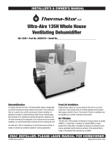
INSTALLING THE DUCT COLLARS
• Use the screws in the parts bag to attach the duct
collars to the inlet and outlet of the dehumidifier.
The outlet collar has a backflow damper.
• The outlet duct collar may be attached to the top or
end of the unit. Move the outlet cover to the location
not being used.
See Figure 11
.
• Make sure there are no bends in the ductwork
coming off the outlet for a minimum of 4". This
precaution will ensure that the ductwork will not
interfere with the backflow damper function.
1
1
23
5
4
690-2592
Figure 11: Fully Ducted Installations
1 - Inlet Duct Collar
2 - Outlet Cover
3 - Outlet Duct Collar w/
Back Draft Damper
4 - End Discharge
5 - Move Outlet Cover
and Install Outlet
Duct Collar to Top
Discharge Location
6 - Top Discharge

8 English
INSTALLING THE DEHUMIDIFIER
DEHUMIDIFIER LOCATION
• Electrical service access and drain cleaning will
require the removal of the electrical service side
panel
(see Figure 12)
. Allow sufficient space for
service on this side of the unit.
• The filter can be removed from either side of the
dehumidifier. Allow sufficient space for the filter to
be removed and reinstalled.
• If locating the unit where it is not readily accessible
(such as a crawl space, an attic or even a
basement for some individuals), consider controls
such as the Model 76 Dehumidifier Control, which
can be mounted in the living space and wired to
the dehumidifier.
• For attic installations, suspending the dehumidifier is
recommended.
• Always install the dehumidifier in or above a
condensate pan when locating in or above a
finished space.
6"
15"
1
6
3
2
5
4
90-1840
Figure 12: Filter Access Clearance
1 - Electrical Service
and Drain Access
this Side
2 - 6" Minimum
Clearance for
Proper Airflow
3 - 15” Minimum
Clearance for
Filter (Either Side)
4 - Filter
5 - Top View
6 - 6' Power Cord
LEVELING AND RAISING THE
DEHUMIDIFIER
The feet can be adjusted to level the unit and
accommodate drain fittings and condensate pans
as required. Use the top-mounted bubble level to
adjust the feet until the bubble is within the outer circle
(see Figure 13)
. Leveling is required to ensure proper
drainage from the dehumidifier.
If installing a condensate pump to the side of the
unit more elevation than can be provided by the
adjustable feet may be needed. Risers or hanging kits
are available to lift the dehumidifier higher off the floor.
1
3
4
OK OK
NO
2
90-2692
Figure 13: Leveling the Unit
1 - Bubble Level
2 - Bubble Level Detail
3 - 3/4” Drain
4 - 0.38" Minimum
2.00" Maximum
INSTALLING A CONDENSATE PAN UNDER
THE DEHUMIDIFIER
Always install the dehumidifier in or above a
condensate pan when locating it above a finished
space. Adhere to local codes regarding draining of
the condensate pan. If a condensate pump is needed,
make sure it is in the condensate pan as well. Install
a float switch in the condensate pan and/or use the
overflow wires/terminals on the condensate pump
to stop the dehumidifier should overflow occur.
See
Wiring to a Float Switch on page 12.

9 English
INSTALLING THE DRAIN
Using Hard Pipe:
• Install a 3/4" PVC slip x 3/4" MNPT PVC fitting to the
dehumidifier and use 3/4" nominal PVC Schedule 40
pipe to run the condensate line to the nearest floor
drain or to an outside location that slopes away
from the building.
• Always maintain a constant downward slope in
drain piping. Ensure that drain tubing does not
interfere with removal of the side panel or filter door.
• Do not use metal fittings and only hand-tighten
threaded fittings. PTFE thread seal tape is
recommended for threaded connections.
• Install a tee or three-way elbow at the dehumidifier
outlet with a small, capped vertical tube (do not
cement cap in place) to allow for cleaner to be
poured into the drain line
(see Figure 14)
.
• PVC primer and cement is recommended for
slip-fit connections (do not cement threaded
connections).
4
1
3
290-2693
Figure 14: Capped Drain Access for Cleaning
1 - Cap
2 - Small Section
of Drain Tube
3 - 3/4" 3-Way elbow
or Tee and Below
4 - Condensate
Drain Line
Using Flexible Tubing:
• Install the provided 3/4" NPT x 3/4" hose barb fitting
and use 3/4" flexible drain tubing. Hand-tighten the
fitting to the dehumidifier. PTFE thread seal tape is
recommended for threaded connections.
• Always maintain a constant downward slope
from the dehumidifier to the nearest floor drain or
condensate pump, and do not allow soft tubing to
curl up, which may result in air lock.
INSTALLING DUCTWORK
• Use insulated duct when the dehumidifier is located
in an unconditioned space, such as an attic, garage
or crawl space, or if connecting a fresh air duct to
the dehumidifier ductwork.
• Use zip ties, mastic, and tape as needed to seal
the duct connections to the dehumidifier and to
seal the insulation sleeves to prevent condensation
inside the ductwork.
Connecting the dehumidifier to your HVAC system will
pull air to be dehumidified from the whole home and
similarly will discharge air to the whole home. Make sure
the duct system pressure the dehumidifier will have to
operate against does not exceed 0.4" Water Column
(WC) for Model E080 and 0.6" WC for Models E100/E100H.
Measure the system pressure when the HVAC fan is
operating at the highest airflow (speed) setting.
There are not always readily available locations on the
HVAC duct system for connecting 10" ducts, and some
local codes do not allow ducting to the return side of
the HVAC system. If so, another option is to install just
the discharge of the dehumidifier to the HVAC system
or to use dedicated registers for both the inlet and
discharge of the dehumidifier.

10 English
DUCTING THE DEHUMIDIFIER INLET AND OUTLET TO THE HVAC SYSTEM
Return-to-Return Basement Installation Return-to-Supply Basement Installation
1
2
4
19
6'
Min
3
90-1886
5
7
6
8
4
990-1887
Return-to-Return Attic Installation Return-to-Supply Attic Installation
18
14
15
13
11 6'
Min
17
90-1888
12
14
15
10
13
7
6
11
24"
Min
16
90-1889
Figure 15: Four Installation Configurations
1 - Air is Pulled from the Main Return Duct and
Discharged to the Main Return Duct
2 - 10" Duct
3 - 6' Minimum
4 - HVAC/Furnace
5 - Air is Pulled from the Main Return Duct
6 - Model E080 0.4" WC Maximum
7 - Model E100H 0.6" WC Maximum
8 - Air is Discharged to the Supply Duct
9 - 10" Duct
10 - Plenum Box
11 - Air Handler
12 - Plenum
13 - Filter
14 - Condensate Pan
15 - 10" Diameter Insulated Duct Both Sides
16 - 24" Minimum
17 - 6' Minimum
18 - Plenum Box or Y-Fitting
19 - Dehumidifier
• Use when both sides of the duct system are
accessible
(see Figure 16)
.
• When ducting from return to supply, the HVAC
blower does not need to be running when the
dehumidifier is running.
• When ducting return to supply, allow adequate
space before the first branch duct to ensure the
warm dehumidified air is thoroughly mixed with the
HVAC system air.
• When ducting from return to return, wire the
dehumidifier to the HVAC system as shown in
Figure 20
to ensure the HVAC blower runs when the
dehumidifier is operating.
• Wire the dehumidifier to the HVAC system
(
see Figure 20
for exact wiring) and set up the
dehumidifier to be disabled when the AC is running.

11 English
DUCTING THE DEHUMIDIFIER OUTLET TO THE HVAC SYSTEM WITH DEDICATED
DEHUMIDIFIER INLET REGISTER
• To direct dehumidified air away from a potentially
wet AC coil:
−Duct to the supply side of the HVAC system
for air handler applications where air is pulled
through the AC coil
(see Figure 16)
.
Dedicated Return to Main Supply
3
2
1
90-2691
Figure 16: Discharge to Supply Side
1 - Supply
2 - Return
3 - HVAC Equipment
−Duct to the return side of the HVAC system for
furnace applications where air is pushed through
the AC coil. Check local codes to verify that ducting
to the return side of the HVAC system is allowed
(see Figure 17)
.
Dedicated Return to Main Return
1
3
2
90-2691
Figure 17: Discharge to Return Side
1 - Supply
2 - Return
3 - HVAC Equipment
• Wire the dehumidifier to the HVAC system as shown
in
Figure 20
and set up the dehumidifier to be
disabled when the AC is running.
Use dedicated registers to duct the dehumidifier
to the whole home when HVAC system ductwork is
unavailable or impractical
(see Figure 18)
.
2
1
4
6
3
590-1893
Figure 18: Stand-Alone Duct
1 - Air is Pulled from
Ducted Space
2 - Dehumidified Space
3 - 10' Minimum
4 - Dehumidified
Air is Supplied to
Ducted Space
5 - Dehumidifier
6 - Grill with 10" Duct
Collar (2 Places)
WIRING
No additional wiring is needed unless:
• the dehumidifier is ducted to the HVAC system
• a separate, external control such as a thermostat or
dehumidistat is to be used
• a float switch, either integral to a condensate pump
or mounted to the condensate pan, is used
Use 18-22 AWG wire for any needed wiring. Access the
dehumidifier wiring terminals by pulling off the wiring
access cover near the dehumidifier control display
(see Figure 19).
Snap the wiring access cover back into
place after completing all wiring.
1
90-1884
Figure 19: Wiring Access Cover Location
1 - Wiring Access Cover

12 English
WIRING TO THE HVAC SYSTEM
When the dehumidifier is ducted to the HVAC system,
it is recommended that it also be wired to the HVAC
system as shown in
Figure 20
. If ducted to the HVAC
system in a return-to-return configuration, the
dehumidifier must be wired to the HVAC system to
prevent short-circuiting dehumidified air directly
back to the dehumidifier inlet. In a return-to-supply
ducting configuration, running the HVAC fan with the
dehumidifier ensures the warm dry air is mixed with
room air before being discharged to the home.
OPTIONAL W & Y WIRING
Wire the W and/or Y terminal to the HVAC system when
using the ventilation feature of the dehumidifier.
See
Ventilation on page 13.
Wire the dehumidifier Y terminal to the HVAC system to
disable the dehumidifier compressor from operating
when the air conditioning is running.
See Allowing DEH
W/AC on page 16
for additional setup steps required
to access this feature.
+-AB ODTVENT DEH
Sensor DampersRemote
FLOAT
Switch
DH DH
GhRf Cf Gs YW
HVAC EQUIP.
G
R
C
W
Y
R
C
G
W
Y
1
2
4
3
5
90-1859
Figure 20: Wiring to HVAC System
1 - Existing Wire
2 - New Wire
3 - Thermostat or Zone
Control Board
4 - HVAC Equipment
5 - Optional Wires
WIRING TO EXTERNAL OR REMOTE
CONTROLS
The dehumidifier can be wired to an external control
that senses the humidity in the living space, such as
an AprilAire Thermostat or the Model 76 Dehumidifier
Control. This is most often done when the dehumidifier
is ducted to the HVAC system and is located in a
hard-to-reach location such as an attic or basement.
The Model 76, when used as a remote control,
allows the user to see the humidity sensed by the
dehumidifier and adjust the dehumidifier setting from
a remote location. This is most often used when the
dehumidifier is not ducted to the HVAC system and
serves a hard-to-reach location such as a crawl space
or basement.
If using an external control, wire to the DH terminals
of the dehumidifier
(see Figure 21)
. Most external
controls use a normally open switch that closes with
a dehumidification demand, in which case leave the
NC/NO switch in the NO position. For controls that use
a normally closed switch, put the NC/NO switch in the
NC position. If using the AprilAire Model 76 as a remote
control, wire to the {+ - A B} terminals. Refer to the
installation instructions for the control being used for
wiring details.
1290-2694
Figure 21: Wiring to an External or Remote Control
1 - Use for External
Control Applications 2 - Use for Remote
Control Applications
WIRING TO A FLOAT SWITCH
Use only if the installation includes a float switch or
a condensate pump. The dehumidifier leaves the
factory with a jumper wire installed in the float switch
terminals. Remove the jumper and wire the float switch
terminals to the float switch or condensate pump
overflow switch as shown in
Figure 22
.

13 English
1
90-1857
FLOAT
Switch
DH DH
Figure 22: Float Switch Wiring
1 - Normal Closed
Float Switch
VENTILATION
The dehumidifier can activate a normally closed
damper to bring in outdoor air through a fresh air
intake duct. This feature cannot be used when a Model
76 has been installed in a remote control application
and should not be used in two-zone installations.
1. Install the Fresh Air Inlet (FAI) duct and damper as
shown in
Figure 23
and
Figure 24
.
3
2
4
5
1
90-1897
Figure 23: Onboard Control Ventilation Installation
1 - Air is Pulled
from Outside
2 - 6' Minimum
3 - HVAC/Furnace
4 - Balancing Dampers
5 - Normally Closed
Vent Damper
MIN
2
3
4
1
90-1898
Figure 24: External Control Ventilation Installation
1 - Air is Pulled
from Outside
2 - HVAC/Furnace
3 - 6' Minimum
4 - Normally Closed
Vent Damper
2. Install the Outdoor Temperature Sensor (ODT) as
shown in
Figure 25
and
Figure 26
– only needed if
ventilation will be limited during high or low outdoor
temperature conditions.
1
4
2
3
B2202617-D
Figure 25: ODT Mounted Outside
1 - North, East or West
Side of Home
2 - Outdoor
Temperature Sensor
3 - Above Expected
Snow Line
4 - Outdoor
Temperature
Sensor Leads

14 English
3
2
1
B2202617-E
Figure 26: ODT Mounted in Intake Duct
1 - Center Line
2 - 36" Maximum
3 - Outside Wall
3. Wire the FAI damper, HVAC equipment and outdoor
temperature sensor to the dehumidifier control as
shown in
Figure 27
.
+-ABODT VENTDEH
Sensor DampersRemote
FLOAT
Switch
DHDH
Gh Rf Cf Gs YW
HVAC EQUIP.
G
R
C
W
Y
R
C
G
W
Y
4
1
3
2
5
90-1861
Figure 27: Ventilation Wiring
1 - Optional Outdoor
Temperature Sensor
(Model 8052)
2 - 6" Normally Closed
Damper or 8190FF
3 - 24 VAC (10 VA
MIN) Transformer
(E100V: Use external
24V port)
4 - HVAC Equipment
5 - Thermostat or Zone
Control Board
4. Use the setup menu to ENABLE ventilation:
a. Enter the installer setup menu
(see page 15)
.
b. Press the Mode button until the words VENT
DISABLE appear.
c. Press the s or t button to change to VENT
ENABLE.
d. Press the Mode button and the words VENT
TIMED will appear. Press the s or t button to set
temperature limits:
• TIMED: no temperature limits
• AUTO – B: Ventilation is not allowed if the ODT
> 100°F or ODT < 0°F; ventilation is allowed only
when the heat is on if the ODT is between 0°F
and 20°F
• AUTO – C: Ventilation is not allowed if the ODT
> 100°F or ODT < 0°F
• AUTO – D: Ventilation is not allowed if the ODT
> 90°F; ventilation is allowed only when the
heat is on if the ODT is between 0°F and 40°F
e. Press the Mode button and then use the s or t
button to set the ventilation time (minutes/hour).
f. Press the Mode button repeatedly until the word
DONE appears on the display.
Whenever the heating, cooling or dehumidifier is
turned on, the ventilation damper will open and bring
in outdoor air. If the equipment doesn’t run for the set
number of minutes, the dehumidifier will turn on the
HVAC fan at the end of the hour to ensure ventilation
needs are met.
ZONING THE DEHUMIDIFIER
The dehumidifier can be configured to condition two
independent spaces. Zoning requires the installation of
ductwork and dampers to direct air to and from two
locations. Scan the QR code for details on zoning the
installation.
OTE: NDehumidifier zoning is not recommended in
HVAC zoning applications.
In this installation the dehumidifier controls the
humidity in two separate zones, a Primary and
Secondary Zone. The dehumidifier will dehumidify the
Primary Zone as the first priority and will switch to the
Secondary Zone after the dehumidification needs of
the Primary Zone have been satisfied.
IMPORTANT: Normally Closed dampers must be
installed in the ducts serving the Primary Zone and
Normally Open dampers installed in the ducts serving
the Secondary Zone.
REQUIRED COMPONENTS
• 10" ductwork and fittings
• Grilles with 10" duct collars
• Drain line
• 2 – AprilAire Model 6510, 10" Normally Closed damper
• 2 – AprilAire Model 6610, 10" Normally Open damper
• 24 VAC transformer (40 VA min.) for dampers
OTE: N5442 Basement Kit includes 2 – 6510 Dampers,
2 – 6610 Dampers and a 24 VAC (40 VA) transformer.

15 English
9
4
5
6
7
8
1
2
3
6'
Min
90-1875
Figure 28: Whole-Home Primary Zone Installation
1 - Return from
Secondary Zone
2 - Normally Closed
Dampers
3 - Return Duct
4 - To/From Primary
Zone
5 - Supply Duct
6 - Supply to
Secondary Zone
7 - Normally Open
Damper
8 - Normally Open
Damper
9 - 6' Minimum
+- AB ODT VENT
DH DH
Gh Rf Cf Gs YW
DEH
FLOAT
Switch
2
1
3 4
5
68
7
90-1896
Figure 29: Two-Zone Wiring On-Board Control
1 - FLOAT Switch
2 - Remote
3 - Sensor
4 - Dampers
5 - HVAC Equipment
6 - 24 VAC (40 VA Min.)
7 - Normally CLosed
(Primary Zone)
8 - Normally Open
(Secondary Zone)
OTE: NDehumidifier zoning is not recommended in
HVAC zoning applications.
INSTALLER SETUP
Enter the setup menu if:
• the dehumidifier is ducted to the HVAC system
• an external or remote control will be used
• ventilation or zoning will be used
1. Plug unit in and turn power switch ON.
2. The onboard control screen should display OFF. If
not OFF, press the ON/OFF button to turn the unit OFF.
OTE: N If the display backlight is not on, the first button
press (any button) will only turn on the backlight. Press
the button a second time to achieve function.
3. Hold the MODE button on the onboard control for 3
seconds to enter the installer setup menu.
4. Navigate through the following screens to set up
the dehumidifier for the installed application.
5. Use the s or t button to select items and use the
MODE button to switch to the next setup option.
To exit the installer setup, scroll through all options
using the MODE button.
6. After the installer setup options have been
completed, the word DONE will blink for 3 seconds
and the control will return to the OFF screen.

16 English
SETTING UP REMOTE CONTROL – CRAWL
SPACE/SEALED ATTIC
If wiring to a Model 76 for remote control (
see page
17
for details) press the s or t button to ENABLE.
SETTING UP VENTILATION
See page 13
for details if using the dehumidifier for
ventilation.
SETTING UP ZONING
See page 14
if zoning the dehumidifier.
SETTING UP EXTERNAL CONTROL
If wiring to an external control (
see page 12
for
details) press the s or t button to ENABLE.
ALLOWING DEH W/AC
To allow dehumidification during active air
conditioning, select ENABLED and press the MODE
button.
To disable dehumidification when the air conditioning
is on, on select DISABLED and press the MODE button.

17 English
APPLYING AN RH OFFSET
An offset can be applied to the onboard humidity
reading to avoid discrepancies with other humidity-
measuring devices in the home. Use the s or t button
to select an offset from -5% to 5%. Press the MODE
button to exit the installer setup screens.
STARTING UP THE UNIT AND
SEQUENCE OF OPERATION
Use the ON/OFF Power Switch near the power cord to
apply power to the dehumidifier.
USING THE DEHUMIDIFIER CONTROL
ONLY
1. Press the ON/OFF Button to turn the dehumidifier
control ON. The display will show the current
humidity setting, and the dehumidifier blower and
HVAC blower (if wired to the HVAC system) will turn
on to start sampling.
The setting will be replaced by the measured
humidity and the words AIR SAMPLING appear on the
display.
2. Use the s or t button to adjust the humidity setting
as desired. The recommended initial setting is
between 55% and 59%.
3. After three (3) minutes of sampling, the measured
humidity will be compared to the setting:
a. If the humidity is above the setting, the
dehumidifier compressor turns on and the
words AIR SAMPLING will be replaced by the word
DEHUMIDIFYING. The compressor remains on until
the measured humidity falls 3% RH below the
setting.
b. If the measured humidity is below the setting,
the blowers turn off and the display returns to
showing the RH setting.
4. The dehumidifier will sample again every 60
minutes, or at any time if the humidity setting is
lowered.
USING A MODEL 76 AS A REMOTE
CONTROL
1. Press the ON/OFF Button to turn the dehumidifier
control ON. The display will show the word REMOTE
to indicate that a remote control is to be used to
control the dehumidifier.
2. At the Model 76, press the ON button; the Model 76
will display the RH measured at the dehumidifier,
and the dehumidifier blower will turn on to start
sampling the air.
3. Use the s or t button on the Model 76 to adjust the
dryness level as desired. The dryness levels range
from 1 to 7, with 1 being least dry and 7 being most
dry; the recommended initial setting is 3.
4. After three (3) minutes of sampling, the measured
humidity will be compared to the setting:
a. If the humidity is above the setting, the
dehumidifier compressor turns on and the word
ON flashes on the Model 76 display.
b. If the measured humidity is below the setting, the
dehumidifier blower turns off.
5. The dehumidifier will sample again every 60
minutes, or at any time if the dryness level is
increased.
USING AN EXTERNAL CONTROL
1. Press the ON/OFF Button to turn the dehumidifier
control ON. The display will show the word EXTERNAL
to indicate that an external control is to be used to
control the dehumidifier.
2. At the external control, initiate a dehumidification
demand. Refer to the literature provided with
the external control. The dehumidifier fan and
compressor, and the HVAC fan (if wired to do so) will
turn on and the word DEHUMIDIFYING will appear on
the display of the dehumidifier.
OTE: NWhen using an external control, there is a three-
minute delay after power-up (i.e., ON/OFF Power Switch is
turned ON with unit plugged in) before the dehumidifier
will respond to an external control. This prevents
unanticipated, early start-up after power is applied.
3. Discontinue the demand at the external control; the
dehumidifier and HVAC fan will turn off.
TWO-ZONE OPERATION
The Primary Zone operates as listed for using the
dehumidifier control or an external control. “PRIMARY
ZONE” shows on the display when operating.
The Secondary Zone uses the humidity setting on the
dehumidifier control. During Secondary Zone operation,
the installed dampers are de-energized and the HVAC
blower (if on) stops. “SECONDARY ZONE” shows on the
display when operating.
The Secondary Zone is sampled immediately after
the Primary Zone has finished sampling, or if there
is a call for dehumidification from the Primary Zone,

18 English
immediately after the call has been satisfied. When an
external control is installed, the Secondary Zone will be
sampled once per hour if there has not been a call for
dehumidification from the Primary Zone.
TROUBLESHOOTING
Technical support is available Monday through
Friday 7:00 a.m. to 5:00 p.m. CST at (800) 334-6011. Use
the guides on the following pages to identify and
correct system faults. Contact Technical Support
before replacing the unit or any components and for
additional troubleshooting.
DIAGNOSTIC CODES
When an error occurs, the Diagnostic Code along with
SERVICE REQUIRED will be displayed on the control
screen.
Table 1: Diagnostic Codes
Diagnostic
Code Failure Mode Action Reset
E1 Internal Humidity
or Temperature
Sensor Open or
Shorted
1. Cycle power to clear error code.
2. If error code reoccurs, replace User Interface, Part No. 5445.
Cycle Power
E2 High
Refrigeration
Pressure
1. Verify that the fan works, the backflow damper swings freely,
and there is no blocked or restricted ductwork.
2. If the fault persists, call Technical Support.
Cycle Power
E3 Model 76
Remote Control
Communication
Loss
1. Check connections between Model 76 and dehumidifier control
board. Terminals should be fully inserted and secured in the
control board and Model 76 control terminals.
2. If connections are correct and secure, turn off the dehumidifier
and remove the Model 76. Use a short section of 4-wire cable
to reconnect the Model 76 to the control board. Turn the
dehumidifier back on and increase the dryness level setting on
the Model 76. If the dehumidifier turns on, a problem exists with
the wiring between the dehumidifier and control.
3. If the dehumidifier does not turn on, call Technical Support.
Self-
Correcting
E4 Insufficient
Capacity 1. Check the frost sensor connection at the power board. The
terminal should be fully seated on the power board pins.
2. Remove the side access panel and verify that the sensor is
secured to the suction line.
3. If the sensor is connected and secured to the refrigeration line,
proceed to the next step.
4. Reset the fault by cycling power to the dehumidifier.
5. Turn the humidity setting down (below room/home humidity
level) to make a dehumidification call.
Cycle Power

19 English
Table 1: Diagnostic Codes
Diagnostic
Code Failure Mode Action Reset
E4 Insufficient
Capacity 6. Allow the fan and compressor to run for approximately 10-15
minutes and then enter diagnostic test mode by simultaneously
pressing the s button and MODE button for 3 seconds. The LCD
will display:
• the temperature measured by the internal sensor while also
displaying the words AIR SAMPLING and ON
• the humidity measured by the internal sensor while also
displaying %RH and the word ON
• the frost sensor temperature while also displaying the word ON
Scroll through these values and by using the s or t button.
7. Record values and call Technical Support.
Cycle Power
E5 High
Temperature
Thermistor
Failure
Check the high temperature sensor connection at the power board.
The terminal should be fully seated on the power board pins.
Remove the side access panel and verify the sensor is not damaged
and connected to the refrigeration line coming from the compressor.
If the sensor is connected and secured to the refrigeration line, it
may need to be replaced with Part No. 5456 – contact Technical
Support to confirm.
Cycle Power
E6 Low Temperature
Thermistor
Failure
Check the low temperature sensor connection at the power board.
Remove the side access panel and verify the sensor is not
damaged and connected to the suction line.
If the sensor is connected and secured to the refrigeration line, it
may need to be replaced with Part No. 5455 – contact Technical
Support to confirm.
Cycle Power
E7 Float Switch
Open Empty the condensate pan.
Check the float switch connection at the control board.
If not using a float switch, verify jumper is between float switch
terminals on dehumidifier control board.
If the problem persists, replace the float switch.
Self-
Correcting
E8 Inlet Air
Temperature
Out of 50°F–104°F
Range, or Dew
Point Below 40°F
1. Verify all ductwork is properly sealed.
2. Check for air leakage that might affect the temperature or RH
of the incoming air.
3. If the air temperture is in range and the dew point is above 40°F,
contact Technical Support.
Self-
Correcting
E9 Outdoor
Temperature
Sensor Open or
Shorted
1. Check the sensor connection
at the power board.
2. Remove the wires from the
terminals and measure the
resistance. A short circuit
will have a resistance very
close to 0 Ohms and an
open circuit will have a very
high resistance. Use the
Ohms chart on
page 21
to
approximate the resistance
based on outdoor
temperature.
3. If the sensor is not reading
correctly, replace the sensor,
Part No. 8052.
Outdoor
Temperature Resistance
0°F 84,500
Ohms
20°F 46,000
Ohms
40°F 26,000
Ohms
60°F 15,500
Ohms
80°F 9,500 Ohms
100°F 6,000 Ohms
Self-
Correcting

20 English
Table 2: Troubleshooting Guide
Symptom Possible Reason Troubleshooting Procedure
Dehumidifier
does not turn
on/run.
No power to unit. • Check that the dehumidifier is plugged in.
• Check that the power switch is turned ON.
• Check that the control is turned ON.
• Check that the circuit breaker has not tripped.
Dehumidifier
blower is running
but with little or
no airflow.
Pressure
drop across
dehumidifier is
higher than 0.4"
WC for Model
E080 or 0.6" WC
for Model E100/
E100H.
• Check dehumidifier air filter and wash or replace.
• Check for blocked ductwork and clear.
• Verify that the outlet collar with backflow damper is installed on the
outlet side of the dehumidifier.
• Check if backflow damper is blocked or stuck and remove obstruction.
Dehumidifier
blower is running
but compressor
is not.
Float Switch
open (E7 appears
on display).
• If float switch is installed, check connections at control board and
empty the condensate pan.
• If no float switch is installed, check that the jumper is installed at the
float switch terminals on the control board.
Unit is defrosting. • Frosting occurs when the incoming air is cool and dry, normally during
Spring or Fall, or the airflow is restricted. Frosting due to cold/dry
conditions is a normal part of operation and “DEFROSTING” will show on
the display. If it is not cool and dry, look for blocked ductwork or a dirty
filter.
Inlet air
temperature is
outside of the
50°F–104°F range
or the dew point
is below 40°F
and there is a
demand for
dehumidification.
• Verify all ductwork is properly sealed. Dehumidification will restart by
itself when the incoming air temperature is within range and the dew
point is above 40°F. E8 appears on the display when inlet air conditions
prevent operation.
When zoned,
the dehumidifier
damper does
not open in
INSTALLER TEST
mode.
Incorrect
damper wiring or
bad connection.
• Verify wiring between dampers and 24 VAC transformer.
• If wired for Two Zone operation, verify that 24 VAC transformer is 40 VA
minimum.
• Check all wiring connections between dampers and control board.
• Verify the normally closed dampers are in the Primary Zone ductwork
and the normally open dampers are in the Secondary Zone ductwork.
/